Table of Contents
Advertisement
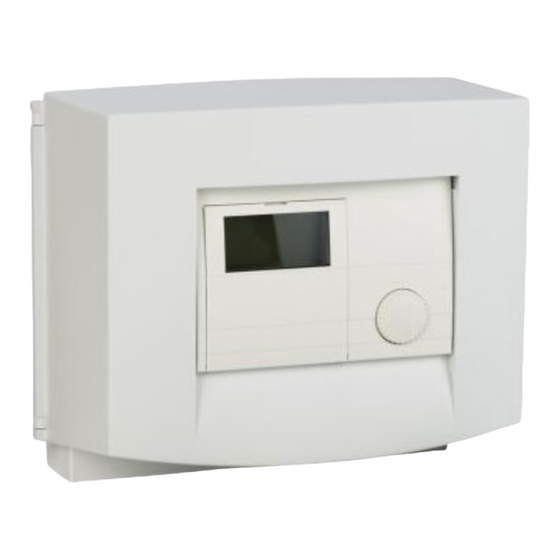
WPMW II, WPMS II
Heat pump manager for heating system heat pumps
Operation and installation instructions
Installation and commissioning as well as the maintenance of this equipment must only be carried
out by an authorised qualified contractor in accordance with these instructions.
Index
Operating instructions
1
Equipment overview
1.1 Equipment description
1.2 Operating and installation instructions
1.3 Maintenance and care
1.4 Important information
1.5 Operation
2
Adjustments
2.1 Operating modes (Control level 1)
2.2 Equipment menu (Control level 2)
2.3 Remote control FE 7
Installation instructions
1
Standard delivery
2
Wall mounting
3
Control panel mounting
4
Electrical connection
4.1 Electrical cables/leads
4.2 Fuses
4.3 Mains supply
4.4 Circulation pump and mixers
4.5 Temperature sensor
4.6 BUS connection
4.7 Remote control FE 7
4.8 Connection array WPMW II
4.9 Connection array WPMS II
5
Commissioning
5.1 BUS initialisation
5.2 System configuration
5.3 Reset options WPM II
5.4 Reset options IWS
5.5 Commissioning summary
5.6 Commissioning details
5.7 Fault remedies
5.8 Commissioning list
5.9 Checking adjustments at the IWS
6
Tables
6.1 Specification
6.2 Standard settings
6.3 Heating and DHW programs
Systemsketch 1
Systemsketch 2
Systemsketch 3
2
2
2
2
2
3
3
4
4
5
11
12
12
12
12
12
12
12
12
12
12
14
14
15
16
17
17
17
17
17
18
20
27
31
32
33
33
33
34
35
35
36
Advertisement
Table of Contents

Related Manuals for STIEBEL ELTRON WPMW II


Summary of Contents for STIEBEL ELTRON WPMW II
- Page 1 4.3 Mains supply 4.4 Circulation pump and mixers 4.5 Temperature sensor 4.6 BUS connection 4.7 Remote control FE 7 4.8 Connection array WPMW II 4.9 Connection array WPMS II Commissioning 5.1 BUS initialisation 5.2 System configuration 5.3 Reset options WPM II 5.4 Reset options IWS...
-
Page 2: Equipment Summary
The three-wire databus enables rapid instal- over all control and regulating processes for all lation and system extension using the MSM heat pumps from Stiebel Eltron. Subject to the relevant system, ob- mixer module Connected heat pumps are controlled via the serve the operating and installation ... -
Page 3: Heat Pump Types
1.4 Important information Vital facts in brief Adjustments The heat pump manager must only be installed and maintained by quali- All adjustments follow the same pattern: fied contractors. Heat pump types The description of individual functions vari- es between the different heat pump types. Therefore, three types of heat pump are Opening the control flap toggles the manag- determined, which are identified in this do-... -
Page 4: Operating Modes
Display (including all elemets) Heating times for central heating and DHW (black) 14-digit plain text display Day mode HC 1 Compress run Switching time pairs for central heating and DHW operation 2. HS RUN DEFROST Setback mode for heating circuit 1 Heat source 2 (emergency work) DHW operation Constant setback mode... - Page 5 2.2 Equipment menu (Control level 2) Select the required menu point with the rotary selector. With the menu item ROOM TEMP 1 you can select the SET ROOM TEMP for day and setback ROOMTEMP HC1 mode for heating circuit 1. The actual room temperature can also be scanned, as soon as the FE 7 remote control has been connected and allocated to heating circuit 1.
- Page 6 Adjustments at control level 2 for users and contractors Room temperature HC 1 SET Roomt night Back With the menu item ROOM TEMP 1 you can select the set room temperature for day and setback mode for heating circuit 1. Changing these parameters results in a parallel offset of the heating curve.
- Page 7 Holiday and party program SET DHW NIGHT In holiday mode, the heat pump system ope- TIME rates in setback mode, and frost protection for DHW heating is active. Holiday mode is displayed with the flap closed. For the start of the holidays, the year, month and day are ente- red;...
- Page 8 – Actual DHW temperature Note: – Set DHW temperature Actual or set temperatures will not be dis- – Actual HP return temperature (HC 1) played, if the corresponding sensor is not Year STOP – Set HP return temperature (HC 1) connected.
-
Page 9: Heating Curves
Open the control flap. Heating curve diagram Heating Curves One heating curve respectively can be adjusted for heating circuit 1 and heating circuit 2. At the factory, heating curve 0.6 is set up for heating circuit 1 and heating curve 0.2 for heating circuit 2. -
Page 10: Heat Circuit
Heating programs Heat START 21C The HTG PROG menu item enables you to Heat STOP 21C adjust associated heating programs for hea- ting circuit 1 and 2 respectively. You can adjust your heating system as follows: – for each individual day of the week SAT to SUN (Monday, ..., Sunday) Heat START 21C... - Page 11 2.3 Remote control FE 7 DHW programs DHW STOP 45C The DHW PROG menu item enables you to adjust the times for the day and night tempe- ratures for DHW heating. You can adjust your DHW heating as follows: – for each individual day of the week (Monday, ..., Sunday) DHW START 45C...
-
Page 12: Installation Instructions
2 Wall mounting (WPMW II) The supply voltage at terminal L and the Subject to parameter settings, the DHW cir- The WPMW II is exclusively designed for wall phase L´ switched by the power supply unit culation pump relay output can also be used mounting. - Page 13 The outside temperature sensor function of a solar heating system. The sensor should be freely subjected to weather influ- on collectors from Stiebel Eltron is installed ences. However, avoid locations above win- on the last collector, viewed in the flow direc- dows, doors and air ducts and those affected tion of the heat transfer medium.
- Page 14 4.6 BUS connection Required temperature sensor As part of the BUS cable connection, not only the electrical interconnection for the system communication will be created. Only connect the BUS cable during commissioning. The correct BUS connection has a vital influ- ence on the function of the heat pump system WPWE-, WPF-M- system (see sections 5.1 and 6.1)
- Page 15 Wedge The connection array of the WPMW II has been designed in accordance with current safety standards into LV and mains voltage areas. All cables/ leads are routed through the ducts and secured in the wall mounting housing with the red wedges supplied. Make all connections in accordance with the WPMW II designations.
- Page 16 4.9 Connection array WPMS II Internal wiring Make the WPMS II connections in accordance with the connection array shown. For this, insert the plugs supplied as follows onto the WPMS II to provide a complete complement: LV area Mains voltage area Heat meter pulse input Mixer circuit pump Earth...
- Page 17 5 Commissioning 5.3 Reset options WPM II After each BUS connection is made, a further The system can be commissioned after the concurrent figure must be shown in the 5.3.1 Reset by turning the rotary switch installation of all heating components required Display after no more than 2 min.
- Page 18 5.5 Commissioning Parameter (as shown in the Display) FIRST STARTUP ENTER CODE LANGUAGE GERMAN --------- MAGYAR CONTRAST DISPLAY ACTUAL RTRN T OUTSIDE TEMP DHW TEMP MIXER TEMP EMERG OPERTN ON / OFF SYSTEM TYPE ON / OFF SOLAR OPERTN HEAT QUANTITY BACK SOLAR TEMP IMPULSE RATE...
- Page 19 HTG CURVE GAP SET BOILER T °C ON TIME HS2DHW ON / OFF SUPPORTED INDEPENDENT ALONE BACK DHW LIMIT °C DUAL MODE DHW °C DHW OPERATION DHW PRIORITY DHW PARALLEL DHW PART PRIOR BACK DHW AUTO OFF / ON DHW O-SIDE-TEMP BACK WW-ECO ON / OFF...
-
Page 20: System Type
5.6 Commissioning details The „Emergency operation“ parameter can been set to ON. The standard setting for im- be set to ON or OFF. pulse rate is 10, and the unit litre s/impulse. Not only the adjustments at control level 2 Emergency operation set to ON: The heat quantity results from determining but also the system-specific parameters must... -
Page 21: Pump Cycles
ON. The system then heats to the selected When regulating to a fixed temperature, sum- stantly and is only switched OFF in summer low end temperature (Low end temp para- mer mode is inactive for heating circuit 1. operation. meter). This temperature is then held for the Outside temperature parameter: The heating circuit pump start will be cont- set period (Low end durat parameter). - Page 22 14 RTRN MAX 12 Source and the mixer closes: This only applies if the room sensor influence is set to K > 0. Reverse Frost protection for brine/water and water/ Maximum return temperature control is subject to the following condition: water heat pumps.
-
Page 23: Room Influence
20 SELECT REM CON cuit data, the max. set mixer flow temperature Set the room sensor influence to ≥ 2, if you is used for the controller, which regulates to want the room temperature to be taken into this value. The FE7 remote control can be selected for account. - Page 24 23 Enable HS 2 (HTG) 29 ON T HS2 DHW heat pump is already OFF and the set tempe- rature for HS 2 has not yet been reached Heating operation with HS2 enabled DHW operation with ON TIME HS 2 Start-up conditions for HS 2 are: You can only select this setting with HP type 1 You can only select this setting with HP type...
- Page 25 Priority operation med for DHW are started together with the temperature has been reached; this termi- DHW loading pump, and the remaining heat nates DHW heating. In this case, too, the set WW-Vorlauf WW-Rücklauf DHW flow DHW return pumps with the buffer loading pump for hea- DHW temperature is then overwritten with Puffer-Vorlauf Buffer flow...
- Page 26 vent relay is switched OFF during defrosting, the time limit was 5 hours) create a fatal error, work, reset the idle time again to 20 minutes and the defrost relay is started without delay. this logic is retained. after completing the necessary work. The type of defrosting influences the buffer 42 COMP DLAY CNTR loading pumps.
-
Page 27: Run Times
Example: The high pressure or low pressure li- Single compressor with reverse defros- can be checked under the system parame- miter has responded on the 17.07.03 at 14:50 ting and external HS 2 (BGC or oil fired ters „Commissioning“ and „Info Temp.“. For h representing the latest fault in heat pump 1. - Page 28 Parameter 46 ERROR LIST for HP TYPE 1: Checking all faults according to the fault list Fault Cause Remedy SOURCE MIN The defined minimum source tempera- Check the minimum source temperature and change, if required. Check the source ture was not reached. volume flow.
- Page 29 Parameter 46 ERROR LIST for HP TYPE 2 and 3: Checking all faults according to the fault list Fault Cause Remedy SOURCE MIN The defined minimum source tempera- Check the minimum source temperature and change, if required. Check the source ture was not reached.
- Page 30 Additional parameters avai- Fault display: Sensor fault The heat pump does not run lable for system analysis: The fault code refers to tempera- The heat pump is in standby mode [ ] Parameter 43 QUICK START: ture sensors which can be called Remedy: Change to programming mode Check all heat pump compressors by imple- up under the system parameter Info.
-
Page 31: Commissioning Report
5.8 Commissioning report The controller should be in standby mode during commissioning. This prevents an uncontrolled heat pump start. Please remember to reset the system into its last operating mode. PARAMETER SETTING RANGE STANDARD SYSTEM VALUE Enter Code 0000 - 9999 1000 Language German... -
Page 32: Reset Button
5.9 Checking the settings on the IWS Leuchtdioden Reset button Slide switches (S1) Slide switches (WP-Typ) Slide switches (WP-Typ) LEDs Red LED: Flashing or static: You can select various compressor systems with the slide switches (WP-Typ). Pressing The LED flashes if the heat pump fault occurs PRG enables you to call up the factory set- once. -
Page 33: Specification
Heating curve 2 Only for switching times pair 1; switching time pairs 2 and 3 are pre-programmed. Stiebel Eltron recommends systems without night setback; our systems are set up accordingly. 22:00 - 6:00 (night heat-up to take advantage of favourable HP tarifs) -
Page 34: Heating And Dhw Programs
Heating and DHW programs You may enter your only individual programs into the following tables. Heating circuit 1 Switching times pair I Switching times pair II Switching times pair III Mo - Fr Sa - Su Mo - Su Heating circuit 2 Switching times pair I Switching times pair II Switching times pair III... - Page 35 Anlagenschema 1 Outside temperature sensor Actual room temperature sensor Actual DHW temperature sensor Actual HP return temperature sensor Actual mixer flow temperature sensor Actual HP flow temperature sensor Actual boiler temperature sensor HS 2 Actual source flow temperature Buffer loading pump 1 Buffer loading pump 2 Mixer circuit pump Heating circuit pump...
- Page 36 Anlagenschema 3 Outside temperature sensor Actual room temperature sensor Actual DHW temperature sensor WP-Rücklaufisttemperaturfühler Actual mixer flow temperature sensor Actual HP flow temperature sensor Actual boiler temperature sensor HS 2 Actual source flow temperature Buffer loading pump 1 Buffer loading pump 2 Mixer circuit pump Heating circuit pump DHW loading pump...
- Page 37 Note Note Note...
- Page 38 Note...
-
Page 39: Environment And Recycling
Guarantee For guarantees please refer to the respecti- ve terms and conditions of supply for your country. The installation, electrical connec- tion and first operation of this ap- pliance should be carried out by a qualified installer. The company does not accept liability for failure of any goods supplied which have not been installed and operated in accordance with the... - Page 40 Internet www.stiebel-eltron.hu Internet www.stiebel-eltron.se Nederland Thailand Belgique Stiebel Eltron Nederland B.V. Stiebel Eltron Ltd. Stiebel Eltron Sprl / Pvba Daviottenweg 36 469 Building 77, Bond Street Rue Mitoyenne 897 B-4840 Welkenraedt Postbus 2020 NL-5202 CA‘s-Hertogenbosch Tambon Bangpood 087-88 1465 Fax 087-881597 ...
Need help?
Do you have a question about the WPMW II and is the answer not in the manual?
Questions and answers