Sign In
Upload
Manuals
Brands
ST Manuals
Microcontrollers
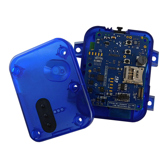
STEVAL-STWINBX1
ST STEVAL-STWINBX1 Manuals
Manuals and User Guides for ST STEVAL-STWINBX1. We have
3
ST STEVAL-STWINBX1 manuals available for free PDF download: Quick Start Manual, User Manual
ST STEVAL-STWINBX1 User Manual (51 pages)
Getting started with the STM32Cube function pack Motor Control high speed datalogging
Brand:
ST
| Category:
Microcontrollers
| Size: 16 MB
Table of Contents
FP-IND-DATALOGMC Software Expansion for Stm32Cube
2
Overview
2
Architecture
2
Figure 1. FP-IND-DATALOGMC Software Architecture
2
Folder Structure
3
Apis
3
Figure 2. FP-IND-DATALOGMC Package Folder Structure
3
Getting Started
4
System Configuration
4
Figure 3. System Configuration
4
Figure 4. Flex Cable and Power Supply Connections
4
Figure 5. Power Supply Chain
5
How to Program EVLSPIN32G4-ACT
6
Figure 6. Motorcontrol Workbench - Step 1
6
Figure 7. Motorcontrol Workbench - Step 2
6
Figure 8. Motorcontrol Workbench - Step 3
6
Figure 9. Motorcontrol Workbench - Step 4
7
Figure 10. Motorcontrol Workbench - Step 5
7
Figure 11. Motorcontrol Workbench - Step 6
8
Figure 12. Motorcontrol Workbench - Step 7
8
Figure 13. Motorcontrol Workbench - Step 8
9
Figure 14. Motorcontrol Workbench - Step 9
9
How to Program Stwin.box
10
FFOTA - Fast Firmware Update over the Air
10
Figure 15. Motorcontrol Workbench - Step 10
10
Figure 16. FP-IND-DATALOGMC Application Binary Folders
10
Figure 17. Double-Bank Flash Memory
11
Figure 18. Stwin.box Antenna
11
How to Program the Stwin.box in "USB Mode
12
Figure 19. Firmware Upgrade Procedure
12
Figure 20. Stm32Cubeprogrammer - USB Mode Selection
13
Figure 21. Stm32Cubeprogrammer - Connection
13
How to Program the Stwin.box with an External Debugger
14
Figure 22. Stm32Cubeprogrammer - Programming
14
Figure 23. Stwin.box and STLINK-V3MINIE Programmer
14
How to Handle Double Bank Flash Memory
15
Figure 24. Stwin.box, Adapter, and STM32 Nucleo Development Board
15
Figure 25. Stwin.box and ST-LINK/V2 Debugger (JTAG 20-Pin 2.54 MM Pitch Connector)
15
Figure 26. Swap Flash Bank with Mobile App
16
Figure 27. Swap Flash Bank with Stm32Cubeprogrammer 1/4
16
Figure 28. Swap Flash Bank with Stm32Cubeprogrammer 2/4
17
Figure 29. Swap Flash Bank with Stm32Cubeprogrammer 3/4
17
DATALOGMC Sample Application
18
USB Mode
18
Figure 30. Swap Flash Bank with Stm32Cubeprogrammer 4/4
18
Figure 31. Device Manager Windows
19
Figure 32. Device Manager Settings
19
Hsdatalog_Mc_Gui
20
Figure 33. High Speed Motor Control Datalog SW
20
Figure 34. Real Time Plot GUI - Fast Telemetries Configuration
21
Figure 35. Real Time Plot GUI - Data Streaming and Labelling
21
Figure 36. Real Time Plot GUI - Floating Widgets
22
Figure 37. Real Time Plot GUI - Offline Plot (1 of 2)
22
Figure 38. Real Time Plot GUI - Offline Plot (2 of 2)
23
Stblesensor App
24
Figure 39. Stblesensor App (1 of 3)
24
Figure 40. Stblesensor App (2 of 3)
25
SD Card Considerations
26
Figure 41. Stblesensor App (3 of 3)
26
Data Labelling
27
Figure 42. Tags Configuration Using the Stblesensor App
27
Figure 43. Tags Configuration Using Python GUI
28
Figure 44. Enabling Tags in Standalone Mode through the Device_Config.json File
28
Figure 45. Acquisition_Info.json with Tag References
29
Hsdpython_Sdk
30
Figure 46. Hsdpython_Sdk Available Scripts
30
How to Install Python
31
Figure 47. Hsdpython_Sdk Packages
31
Figure 48. Install Python
31
Hot to Install Hsdpython_Sdk
32
Figure 49. Python Setup
32
Acquisition Folders
33
Device_Config.json
33
Figure 50. Hsdpython_Sdk Options
33
Figure 51. Device_Config.json Fields
34
Figure 52. Iis2Dlpc_Acc Component
35
Figure 53. Fast_Mc_Telemetries Component
36
Acquisition_Info.json
37
Figure 54. Informative Components
37
Figure 55. Tags_Info Component
37
Raw Data Files (.Dat)
38
Figure 56. Acquisition_Info.json
38
Figure 57. Sensor Raw Data Folder
39
Figure 58
39
Device Template Model
40
ODR and FS Mapping Table
40
Figure 59. Mapping Table 1
40
Figure 60. Mapping Table 2
41
Figure 61. Mapping Table 4
41
Figure 62. Mapping Table 5
41
System Setup Guide
42
Hardware Description
42
STEVAL-STWINBX1 Evaluation Kit
42
EVLSPIN32G4-ACT Evaluation Kit
42
Figure 63. Stwin.box Mounted with the Plastic Case
42
Software Setup
43
Figure 64. EVLSPIN32G4-ACT Evaluation Kit
43
Datalog Troubleshooting
44
Revision History
45
Table of Contents
46
List of Tables
48
Advertisement
ST STEVAL-STWINBX1 User Manual (58 pages)
SensorTile wireless industrial node development kit
Brand:
ST
| Category:
Microcontrollers
| Size: 4 MB
Table of Contents
Figure 1. Stwin.box Mounted with the Plastic Case
1
Getting Started
2
Precautions for Use
2
Features
2
Kit Components
2
Layout of the Core System Board (STEVAL-STWINBX1) Components
3
Figure 2. STEVAL-STWINBX1 Components
3
Figure 3. Layout of the Core System Board Top Components
3
Core System Board
4
Figure 4. Layout of the Core System Board Bottom Components
4
Figure 5. STEVAL-STWINBX1 Block Diagram
4
Functional Blocks
5
Sensing
5
Figure 6. STEVAL-STWINBX1 Evaluation Kit (Top View)
5
Figure 7. STEVAL-STWINBX1 Evaluation Kit (Bottom View)
5
Figure 8. STEVAL-STWINBX1 - Overview of the Sensing Components
6
Figure 9. STEVAL-STWINBX1 - Sensors on the Top Side
6
Table 1. ILPS22QS I/O Configuration
7
Figure 10. STEVAL-STWINBX1 - Sensors on the Bottom Side
7
Table 2. STTS22H I/O Configuration
8
Table 3. ISM330DHCX I/O Configuration
8
Table 4. IIS3DWB I/O Configuration
9
Table 5. IIS2DLPC I/O Configuration
9
Table 6. IIS2ICLX I/O Configuration
10
Table 7. IIS2MDC I/O Configuration
10
Processing and Connectivity
11
Table 8. IMP23ABSU I/O Configuration
11
Table 9. IMP34DT05I/O Configuration
11
Figure 11. Main Connectivity Components and the STM32U585AI Processing Unit
12
Figure 12. MCU and Connectivity Components (Top View)
12
Figure 13. MCU and Connectivity Components (Bottom View)
13
Table 10. Bluenrg2-M2 I/O Configuration
14
Table 11. MXCHIP EMW3080 I/O Configuration
15
Figure 14. MXCHIP EMW3080
15
Table 12. STR485LV I/O Configuration
16
Table 13. USB Connector I/O Configuration
16
Table 14. STSAFE-A110 I/O Configuration
16
Table 15. Micro-SD Card Socket I/O Configuration
16
Power Management
17
Figure 15. Power Management of the Stwin.box Core System Board
17
Figure 16. Power and Protections
17
Table 16. BATT1 Connector Pins and Signals
20
Figure 17. BATT1 Connector
20
Figure 18. Stwin.box Core System Board - Power Supply Block Diagram
21
Figure 19. Stwin.box Core System Resistors and Solder Bridges (Top View)
22
Figure 20. Stwin.box Core System Resistors and Solder Bridges (Bottom View)
22
Table 17. Flexible Expansion Connector Pins
23
Figure 21. Mapping of the 34-Pin Connector Resources
23
How to Assemble the Stwin.box
25
Figure 22. Connecting the Core System Board to the Battery
25
Figure 23. Stwin.box Core System Board Placed in the Bottom Case
26
Figure 24. Stwin.box Assembly
27
Figure 25. Stwin.box Mounted with the Plastic Case
27
How to Program the Board
28
How to Program the Stwin.box in "USB Mode
28
Figure 26. Stm32Cubeprogrammer - USB Mode Selection
29
Figure 27. Stm32Cubeprogrammer - Connection
29
How to Program the Stwin.box with an External Debugger
30
Figure 28. Stm32Cubeprogrammer - Programming
30
Figure 29. Stwin.box and STLINK-V3MINI Programmer
30
Figure 30. Stwin.box, Adapter, and STM32 Nucleo Development Board
31
Figure 31. Stwin.box and ST-LINK/V2 Debugger (JTAG 20-Pin 2.54 MM Pitch Connector)
31
Default Application
33
Figure 32. Stwin.box Antenna
33
Figure 33. Firmware Upgrade Procedure
34
Schematic Diagrams
35
Figure 34. Core System Board Circuit Schematic (1 of 8)
35
Figure 35. Core System Board Circuit Schematic (2 of 8)
36
Figure 36. Core System Board Circuit Schematic (3 of 8)
37
Figure 37. Core System Board Circuit Schematic (4 of 8)
38
Figure 38. Core System Board Circuit Schematic (5 of 8)
39
Figure 39. Core System Board Circuit Schematic (6 of 8)
40
Figure 40. Core System Board Circuit Schematic (7 of 8)
41
Figure 41. Core System Board Circuit Schematic (8 of 8)
42
Figure 42. Adapter Board Circuit Schematic
43
Bill of Materials
44
Table 18. STEVAL-STWINBX1 Bill of Materials
44
Table 19. Core System Board Bill of Materials
44
Table 20. Adapter Board Bill of Materials
51
Kit Versions
52
Table 21. STEVAL-STWINBX1 Versions
52
Regulatory Compliance Information
53
Revision History
54
Table 22. Document Revision History
54
Table of Contents
55
List of Tables
56
List of Figures
57
ST STEVAL-STWINBX1 Quick Start Manual (66 pages)
Function pack for high speed datalogging and ultrasound processing
Brand:
ST
| Category:
Microcontrollers
| Size: 5 MB
Table of Contents
Hardware and Software Overview
3
Hardware Overview
4
Software Overview
15
Programming Options
20
Run the Application
34
Auto Mode
49
Advertisement
Advertisement
Related Products
ST STEVAL-STWINKT1
ST STEVAL-STWINKT1B
ST STEVAL-IDB007V1M SPBTLE-1S
ST STEVAL-IDB003V1
ST STEVAL-FKI868V1
ST STEVAL-ISB68WTX
ST STEVAL-2STPD01
ST STEVAL-IPC004V1
ST STEVAL-MKBOXPRO
ST STEVAL-STRKT01
ST Categories
Motherboard
Computer Hardware
Microcontrollers
Control Unit
Controller
More ST Manuals
Login
Sign In
OR
Sign in with Facebook
Sign in with Google
Upload manual
Upload from disk
Upload from URL