Table of Contents
Advertisement
Quick Links
Advertisement
Table of Contents

Related Manuals for Cypress OSM-2400


Summary of Contents for Cypress OSM-2400
- Page 1 OSDP- Upgraded Wiegand Converte OSM-2400 Product Manual OSM-2400_Manual_221208 Cypress Integration Solutions 35+ Years of Access Control Ingenuity CypressIntegration.com Page 1 2022 Cypress Computer Systems 1778 Imlay City Road, Lapeer, MI 48446 800-807-2977 ©...
- Page 2 The OSM-2400 is an upgraded replacement for the OSM-1000 Wiegand-OSDP converter. The OSM-2400 is used to connect an OSDP reader to a Wiegand controller, or used to connect a Wiegand reader to an OSDP controller. This allows users to begin adopting OSDP and gaining the benefits, such as encrypted communication, without having to replace the entire system.
-
Page 3: Table Of Contents
Cypress OSM-2400 Manual - Table of Contents Table of Contents Topic Page Overview and Specifications OSDP Terminology Using ACU Mode or PD Mode Physical Features & Dimensions Pin Designations Power Input ACU Mode Wiring Diagram PD Mode Wiring Diagram General OSDP Communication Information... -
Page 4: Osdp Terminology
Cypress OSM-2400 Manual - OSDP Terminology This section lists and defines in general terms OSDP terminology used in this manual. Access Control Unit (ACU): Typically the access controller, the ACU is the device on the OSDP bus that controls the PDs. The ACU only sends commands to the PDs and waits for replies. -
Page 5: Using Acu Mode Or Pd Mode
OSM-2400 controls the Wiegand reader by changing the state of its physical I/O according to the OSDP commands. The OSM-2400 can be one of multiple PDs on the OSDP bus. The OSM-2400 will need to have a unique device address (set with DIP switches 1-3 or by the osdp_COMSET command) and the baud rate will need to match the baud rate of the OSDP access controller. -
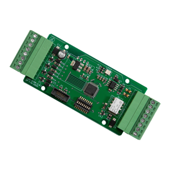
Page 6: Physical Features & Dimensions
Cypress OSM-2400 Manual - Physical Features & Dimensions Status LED DIP Switches Wiegand / OSDP / Relay I/O Header Header 1.90 inches (mounting holes) Ø 0.125 inches x4 1.30 inches 1.50 inches (mounting (overall) holes) 4.03 inches (overall) Page 6... - Page 7 Cypress OSM-2400 Manual - Pin Designations ACU Mode Pin Designations 8 - 16 VDC Input RS-485 B+ Ground RS-485 A- Data 0 Output Ground Data 1 Output Strike N.O. Buzzer Input Strike COM Ground Strike N.C. Red LED Input Ground...
- Page 8 Cypress OSM-2400 Manual - Power Input The OSM-2400 is powered with 8 to 16 VDC (12 VDC typical) for the power input, and draws at most 250 mA of current. There are two power inputs that are connected together (common), shown in green text in the diagram below.
- Page 9 Cypress OSM-2400 Manual - ACU Mode Wiring Diagram Page 9...
- Page 10 Cypress OSM-2400 Manual - PD Mode Wiring Diagram Page 10...
- Page 11 The OSDP session timeout is 8 seconds, as defined in the OSDP specification. In ACU Mode, if the OSM-2400 does not receive a reply from the PD within 8 seconds it will end the OSDP communication session. A new OSDP communication session will be established in order for communication to resume.
- Page 12 PD to read its capabilities. The OSM-2400 will send the PD any control and I/O commands based on the state of the DIP switches and inputs controlled by the Wiegand access controller. If the OSDP reader or PD does not support the I/O command sent by the OSM-2400 it should reply with a NAK.
- Page 13 Cypress OSM-2400 Manual - PD Capability Report (PD CAP) (Cont.) Field Value Meaning Function Code: 04 LED Control (Dual LED Mode) Compliance: 04 Tri-Color LED with Timed Control Number of: 01 Device has 1 LED Function Code: 05 Audio Output...
- Page 14 Cypress OSM-2400 Manual - Status LED The OSM-2400 has a single tri-color LED that displays Red, Green, Blue, and White to indicate the state of the OSDP communication session. ACU Mode Status LED States: Flashing RED: Attempting to poll PD with selected address...
-
Page 15: Led Modes
Cypress OSM-2400 Manual - DIP Switches ON C & K ACU or PD PD Address Mode Select or ACU Invert LED I/O Polling Address Pin State LED Mode Require Secure Select Channel Enable Beep on Read in ACU Mode Page 15... - Page 16 DIP Switch 4 - LED Mode Select: DIP Switch 4 is used to select the LED mode. When DIP Switch 4 is OFF, the OSM-2400 is in Dual LED Mode, for use with Wiegand readers or controllers with 2 LED lines. In Dual LED Mode both the Red and Green LED lines are enabled and there are 4 possible LED states;...
- Page 17 DIP Switch 6 - Require Secure Channel Communication: In PD Mode, when DIP Switch 6 is ON, the OSM-2400 will only reply to attempts by the ACU to start a Secure Channel communication session. The OSM-2400 will reply to all other commands sent by the ACU in clear channel with a NAK.
- Page 18 LED states; RED and GREEN. The OSDP spec does not allow a PD (OSM-2400) to NAK an LED command with the color OFF, so in this case the OSM-2400 will put the Red LED line in the normal state. The table below shows the different states of the Red LED line and how those states correspond to the LED color.
- Page 19 Cypress OSM-2400 Manual - LED Modes (Cont.) When DIP switch 7 is ON, the state of the LED lines are inverted. The tables below show the state of the Red and Green LED Lines when DIP switch 7 is ON.
- Page 20 The SCBK-D / SCBK is used to encrypt the data payload of OSDP messages while in a Secure Channel session. The OSM-2400 SCBK-D is 30 31 32 33 34 35 36 37 38 39 3A 3B 3C 3D 3E 3F (16 bytes in HEX) and is public.
-
Page 21: Using Secure Channel Communication
4. Reset the Secure Channel session now using the new SCBK. Once the new SCBK is set, the OSM-2400 will use the new SCBK in both PD Mode and ACU Mode. The SCBK can be changed by putting the OSM-2400 in PD mode, establishing a Secure Channel communication setting with an ACU using the current SCBK, and having the ACU send an osdp_KEYSET command with the new SCBK. - Page 22 127 (7F Hex). If the osdp_COMSET command is used with the broadcast address, it is important that the OSM-2400 is the only device on the OSDP bus. If more than one device is on the OSDP bus all of them will process the osdp_COMSET command and multiple device will be set to the new device address, causing communication issues on the OSDP bus.
-
Page 23: Acu Mode I/O Overview
OSDP reader (PD). The relay is in the alarm state when the OSM-2400 is not communicating with the PD, and in the normal state when the OSM-2400 is communicating with the PD. If the PD indicates a tamper state with the LSTATR reply the relay will change to the alarm state. If the PD sends the LSTATR reply indicating the tamper state is no longer present, the relay will change to the normal state. - Page 24 LED outputs on the Wiegand access controller. The Wiegand access controller controls the state of the Red and Green LED lines on the OSM-2400, based on the state of the LED inputs the OSM-2400 sends an osdp_LED command to the OSDP reader to change the LED color appropriately.
- Page 25 OSM-2400 will send an osdp_LED command to set the OSDP readers’s LED to off permanently. Single LED Mode: When the Red LED input is in the normal state (5V) the OSM-2400 will send an osdp_LED command to set the OSDP reader’s LED to red permanently.
- Page 26 OSM-2400 will send an osdp_LED command to set the OSDP readers’s LED to off permanently. Single LED Mode: When the Red LED input is in the active state (0V) the OSM-2400 will send an osdp_LED command to set the OSDP reader’s LED to green permanently.
- Page 27 OSM-2400 will send an osdp_LED command to set the OSDP reader’s LED to amber permanently. When the Green and Red LED inputs return to the normal state (5V), the OSM-2400 will send an osdp_LED command to set the OSDP readers’s LED to off permanently.
- Page 28 OSDP reader’s LED to off permanently. Single LED Mode: The off LED color is not supported in Single LED Mode, the OSM-2400 will only send osdp_LED commands to set the OSDP reader’s LED to red or green.
- Page 29 Cypress OSM-2400 Manual - ACU Mode I/O - Buzzer Input When the Buzzer Input is pulled low (0V) the OSM-2400 will send an osdp_BUZ command to the OSDP reader to activate the reader’s buzzer. BUZ On Raw Command Payload (in HEX): 6A 00 02 01 00 00 The table below shows the breakdown of the 6 byte payload.
-
Page 30: Pd Mode I/O Overview
Wiegand data is received from the Wiegand reader the OSM-2400 will send either an osdp_RAW reply or osdp_KEYPAD reply to the ACU depending on the data. If the OSM-2400 receives 4 bits or 8 bits and the data matches keypad data the osdp_KEYPAD reply will be sent. If the 4 bits or 8 bits of data does not match keypad data or a different number of bits is received the osdp_RAW reply... - Page 31 5V only. The Red and Green Outputs are floating (no pull-ups). Dual LED Mode (DIP Switch 4 OFF) is used when the OSM-2400 is used with Wiegand readers that have two LED control lines (typically Red and Green LED lines). Dual LED Mode allows for four LED states (RED, GREEN, AMBER and OFF).
- Page 32 4 bytes - 32 Bits of Credential Data Data When the OSM-2400 receives 4 or 8 bits of Wiegand data and the data matches the data in the “Weigand Data Received” row of the below table, it will reply with the osdp_KEYPAD reply when it is next polled by the ACU.
-
Page 33: Firmware Upload Using File Transfer
The ACU will send the new firmware file to the OSM-2400 over the OSDP bus. After the firmware file has been sent to the OSM-2400, the device will apply the new firmware file and reboot, then the ACU can establish a new OSDP communication session with the OSM-2400. Depending on the baud rate the duration of the firmware upload process varies.
Need help?
Do you have a question about the OSM-2400 and is the answer not in the manual?
Questions and answers