Advertisement
Quick Links
[ Package List ]
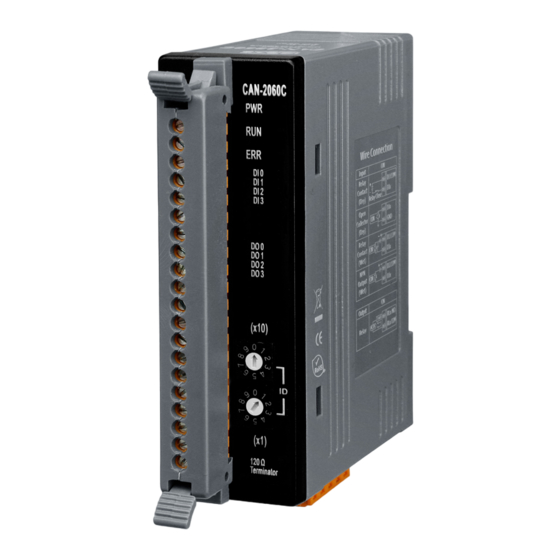
CAN-2060C
CAN Interface
CANopen Specification
Node ID
Baud Rate (bps)
Error Control
Terminator Resistor
Connector
Digital Input
Channels
On Voltage Level
Off Voltage Level
Response Time
ESD Protection
Relay Output
Channels
Type
Max. Load Current
Operate Time
Release Time
Power
Input range
Environment
Operating Temp.
For more information about CAN-2060C, please visit the following website:
http://www.icpdas.com/products/Remote_IO/can_bus/CAN-2060C.htm
CAN-2060C Quick Start
Software CD
Hardware Specification
CiA-301 v4.02, CiA -401 v2.1
1~99 selected by rotary switch
10k, 20k, 50, 125k, 250k, 500k, 800k and 1M
Node Guarding protocol and Heartbeat Producer protocol
Switch for 120 Ω terminator resistor
5-pin screwed terminal block
(CAN_GND, CAN_L, CAN_SHLD, CAN_H, CAN_V+)
4 (Sink/Source)
3.5 ~30 V
DC
1 V
Max.
DC
250 us
+/-4 kV, Contact for each channel
4
Form A (SPST-NO)
5A per channel
10ms Max
5ms Max
Unregulated +10 ~ +30 V
-25 ~ 75 ℃
CAN-2060C Quick Start Ver. 1.20, Apr/2017
Screw Driver
(1C016)
DC
Quick Start
1
Advertisement

Related Manuals for ICP DAS USA CAN-2060C


Summary of Contents for ICP DAS USA CAN-2060C
- Page 1 Operate Time 10ms Max Release Time 5ms Max Power Input range Unregulated +10 ~ +30 V Environment -25 ~ 75 ℃ Operating Temp. For more information about CAN-2060C, please visit the following website: http://www.icpdas.com/products/Remote_IO/can_bus/CAN-2060C.htm CAN-2060C Quick Start Ver. 1.20, Apr/2017...
- Page 2 CAN-2060C Pin Assignments CAN-2060C Quick Start Ver. 1.20, Apr/2017...
- Page 3 CAN-2060C Internal I/O Structure Rotary Switch Value Baud rate (k BPS) 1000 Baud rate and rotary switch CAN-2060C Quick Start Ver. 1.20, Apr/2017...
- Page 4 CAN-2060C Wiring Connection Type CAN-2060C Quick Start Ver. 1.20, Apr/2017...
- Page 5 CAN-2060C CAN Bus Wire Connection Signal Description CAN_V+ Power positive CAN_H Signal high of CAN Bus line CAN_SHLD Cable Shield (FG) CAN_L Signal low of CAN Bus line CAN_GND CAN ground CAN_SHID (FG) is Optional. 2-Wire Connection CAN-2060C Quick Start Ver. 1.20, Apr/2017...
- Page 6 3-Wire Connection 4-Wire Connection (The CAN-2000 is powered by the master device) CAN-2060C Quick Start Ver. 1.20, Apr/2017...
- Page 7 CAN-2060C Firmware Update Step 1 – Set Module to “Bootloader” mode (set Node ID to 00, Baud rate to F). Then power on the module. Step 2 – Run FW_Update_CAN Utility CAN-2060C Quick Start Ver. 1.20, Apr/2017...
- Page 8 (2) Click “Start Firmware Update” button to start firmware update and it will show the total percentage of firmware update in progress bar. After the firmware update finished, it will show the “Firmware Update Success !!” message. CAN-2060C firmware Download: ftp://ftp.icpdas.com/pub/cd/fieldbus_cd/canopen/slave/can-2000c/CAN- 2060C/ FW_Update_CAN Utility Download: ftp://ftp.icpdas.com/pub/cd/fieldbus_cd/canopen/slave/can-2000c/tools/ CAN-2060C Quick Start Ver. 1.20, Apr/2017...
Need help?
Do you have a question about the CAN-2060C and is the answer not in the manual?
Questions and answers