Table of Contents
Advertisement
Quick Links
CANopen Slave Device
Warranty
All products manufactured by ICP DAS are under warranty regarding
defective materials for a period of one year from the date of delivery to
the original purchaser.
Warning
ICP DAS assumes no liability for damages resulting from the use of
this product. ICP DAS reserves the right to change this manual at any
time without notice. The information furnished by ICP DAS is believed to
be accurate and reliable. However, no responsibility is assumed by ICP
DAS for its use, or for any infringements of patents or other rights of third
parties resulting from its use.
Copyright
Copyright @2019 is reserved by ICP DAS.
Trademark
The names used for identification only may be registered trademarks
of their respective companies.
CAN-2084C User's Manual (Version 1.00, Sep/2018) ------------- 1
CAN-2084C
Application User's Manual
Advertisement
Table of Contents

Subscribe to Our Youtube Channel
Related Manuals for ICP DAS USA CAN-2084C


Summary of Contents for ICP DAS USA CAN-2084C
- Page 1 DAS for its use, or for any infringements of patents or other rights of third parties resulting from its use. Copyright Copyright @2019 is reserved by ICP DAS. Trademark The names used for identification only may be registered trademarks of their respective companies. CAN-2084C User’s Manual (Version 1.00, Sep/2018) ------------- 1...
-
Page 2: Table Of Contents
Mode 4: Quadrant Counting ............18 Application ......................19 Object Dictionary ................19 Store and Restore Object ............... 25 Application Object ................26 Default PDO Mapping ..............33 EMCY Communication ..............34 CAN-2084C User’s Manual (Version 1.00, Sep/2018) ------------- 2... -
Page 3: Introduction
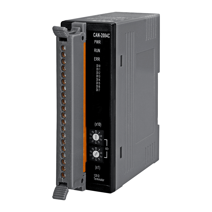
The CAN-2084C is a CANopen slave which follows the CiA 301 version 4.02. The CAN-2084C is a 4/8-channel Counter/Frequency module that provides “Up Counter”, "Frequency”, “Up/Down Counter”, “Dir/Pulse Counter”... - Page 4 Figure 1-1 CAN-2084C CAN-2084C User’s Manual (Version 1.00, Sep/2018) ------------- 4...
-
Page 5: Features
2 μs x 2 = 4 μs, which is 250 kHz as a maximum. Input Maximum Frequency: Frequency Refer to the Minimum Pulse Duration of the High Level, the maximum frequency is highly affected by the duty cycle Frequency Accuracy = ±0.4% EEPROM 128KB CAN-2084C User’s Manual (Version 1.00, Sep/2018) ------------- 5... - Page 6 33 mm x 99 mm x 78 mm ( W x L x H ) Environment Operating -25 ~ 75 ℃ Temp. Storage -30 ~ 80 ℃ Temp. Humidity 10 ~ 90% RH, non-condensing CAN-2084C User’s Manual (Version 1.00, Sep/2018) ------------- 6...
-
Page 7: Application
Application Counting events or totalizing Detecting frequency Monitoring position or speed with quadrature encoder CAN-2084C User’s Manual (Version 1.00, Sep/2018) ------------- 7... -
Page 8: Hardware
Hardware Structure (Bottom View) (Top View) CAN-2084C User’s Manual (Version 1.00, Sep/2018) ------------- 8... -
Page 9: Node Id & Baud Rate Rotary Switch
Node ID & Baud Rate Rotary Switch The rotary switches for node ID configure the node ID of the CAN-2084C module. These two switches are for the tens digit and the units digit of node ID. The node ID value of this demo picture is 32. -
Page 10: 2.3 Led Description
2.3 LED Description Power LED The CAN-2084C needs a 10V~30VDC power supply. Under a normal connection, a good power supply and a correct voltage selection, as the unit it turned on, the LED will light up in red. Run LED The Run LED indicates the CANopen operation state. -
Page 11: Pin Assignment
PIN Assignment CAN-2084C User’s Manual (Version 1.00, Sep/2018) ------------- 11... -
Page 12: Wire Connection
Wire Connection The CAN-2084C has two kind of inputs, isolated and non-isolated (TTL) for different input signals. Users can switch jumper setting on the CAN-2084C board for appropriate signal. These jumpers are located within JP1~JP8. The jumper settings are listed in the following table. The isolated input is set by default. -
Page 13: Input Signal Model
The solution is shown below. TTL Input (XOR=1) When an external TTL signal is input into a CAN-2084C module through the TTL mechanism, the signal will be the same as the external signal. This internal signal isn’t the recommended waveform as the exclusive OR (XOR=1) operation must be executed to invert the waveform. -
Page 14: Digital Low Pass Filter
Digital Low Pass Filter The CAN-2084C includes three independent 2nd-order digital noise filters that can be used to remove noise, and are implemented as follows: The Low Pass Filter can be set to either enabled or disabled. The width of the Low Pass Filter is programmable and can be set within a range from 1 µs to... - Page 15 Consequently, the input signal will be filtered. Similarly, the maximum period of the filtering clock can be calculated to allow the input signal to be passed using the formula H > 2T. CAN-2084C User’s Manual (Version 1.00, Sep/2018) ------------- 15...
-
Page 16: Counter Mode
When InA0 is used as an UP_clock and InB0 is used as a DOWN_clock, counter_0 will be increased by one for every falling edge of InA0 and decreased by one for every falling edge of InB0. CAN-2084C User’s Manual (Version 1.00, Sep/2018) ------------- 16... -
Page 17: Mode 2: Frequency Mode
High Speed Mode will read 11 pulses to calculate average value of those 11 pluses. High Speed Mode will be more accuracy than Normal mode for measurement Frequency. We suggest using High Speed Mode if measurement frequency is more than 10k Hz. CAN-2084C User’s Manual (Version 1.00, Sep/2018) ------------- 17... -
Page 18: Mode 3: Up Counting
Counter_0 will be increased by one when the InA0 phase leads by 90 degrees to InB0. Counter_0 will be decreased by one when the InA0 phase lags by 90 degrees to InB0. CAN-2084C User’s Manual (Version 1.00, Sep/2018) ------------- 18... -
Page 19: Application
1017h Heartbeat time UNSIGNED 16 largest sub-index supported for 1018h UNSIGNED 8 “identity object” vender ID UNSIGNED 32 0x0000013C Produce Code UNSIGNED 32 0x00002026 Revision_number UNSIGNED 32 0x00030001 Serial_number UNSIGNED 32 0x6cd3683c CAN-2084C User’s Manual (Version 1.00, Sep/2018) ------------- 19... - Page 20 Attr Default 1600h Number of entries UNSIGNED 8 1601h Number of entries UNSIGNED 8 1602h Number of entries UNSIGNED 8 … … … … … … 1609h Number of entries UNSIGNED 8 CAN-2084C User’s Manual (Version 1.00, Sep/2018) ------------- 20...
- Page 21 … … … 1809h Number of entries UNSIGNED 8 COB-ID used by TxPDO UNSIGNED 32 80000000h Transmission type UNSIGNED 8 Inhibit time UNSIGNED 16 … … … Reversed Event timer UNSIGNED 16 CAN-2084C User’s Manual (Version 1.00, Sep/2018) ------------- 21...
- Page 22 Up/Down Counter, user need to set Channel 0 and Channel 1 into Up/Down Counting mode. Counter Type Number of counter sets Type Code Input Type Dir/Pulse Counting Mode Up/Down Counting Mode Frequency Mode 03 (Default) Up Counting Mode CAN-2084C User’s Manual (Version 1.00, Sep/2018) ------------- 22...
- Page 23 Type Code Edge Type 0 (default) Falling Rising Frequency Mode Entry Sidx Description Type Attr Default 3004h Number of entries UNSIGNED 8 Channel 0 Frequency mode UNSIGNED 32 … … … … … CAN-2084C User’s Manual (Version 1.00, Sep/2018) ------------- 23...
- Page 24 Number of entries UNSIGNED 8 Channel 0 Low pass filter period UNSIGNED 16 … … … … … Channel 7 Low pass filter period UNSIGNED 16 Note: Time Range: 1μs ~ 32767μs CAN-2084C User’s Manual (Version 1.00, Sep/2018) ------------- 24...
-
Page 25: Store And Restore Object
3001h Overflow value 3002h Clear counter value 3003h Edge mode 3004h Frequency mode 3005h Frequency time out value BB8h 3006h Low pass filter 3007h Low pass filter time 3008h Input signal model CAN-2084C User’s Manual (Version 1.00, Sep/2018) ------------- 25... -
Page 26: Application Object
Counter type of the channel 0~7. If the user wants to change the Counter type, write the type code to the object with index 2004h and subindex 1~8. For example, if the node ID of CAN-2084C is 1, the following command would be used:... - Page 27 SDO client (CAN-2084C) Clear Counter Value (0x3002) This object is used to clear the channels counter value and it’s write only. For example, if the node ID of the CAN-2084C is 1, the commands are as follows: 11-bit COB-ID (bit) Data 8-byte Data (byte) CAN-2084C User’s Manual (Version 1.00, Sep/2018) ------------- 27...
- Page 28 This object can be used to select the detecting method of counter. There are three modes can be selected, falling, rising, or both. For example, if the node ID of CAN-2084C is 1, the commands are shown below: 11-bit COB-ID (bit)
- Page 29 High speed mode. Note: If user doesn’t choose frequency mode in object 0x2004, 0x3004 make no difference to CAN- 2084C module. For example, if the node ID of CAN-2084C is 1, the commands are shown below: 11-bit COB-ID (bit)
- Page 30 If Data0 is 80, that means it fails. Turn On/Off Low Pass Filter (0x3006) User can use this object to turn on/off the low pass filter of channel0~7. For example, if the node ID of CAN-2084C is 1, the commands are shown below: 11-bit COB-ID (bit)
- Page 31 User can use this object to set the low pass filter time of channel0~7. The default value is 1μs, and the range is 1μs ~32767μs(0x01~0x7FFF). For example, if the node ID of CAN-2084C is 1, the commands are shown below:...
- Page 32 Set Module to Operation Mode when powering on (0x2100) This object 0x2100 with subindex 1 defines if the module will enter operation mode automatically when powering on. For example, if the node id of CAN-2084C is 1, the commands are as below: 11-bit COB-ID (bit) 8-byte Data (byte)
-
Page 33: Default Pdo Mapping
SDO server (CAN-2084C) Default PDO Mapping TxPDO mapping list: 180h+x Reserved 280h+x Counter Value ch0 Counter Value ch1 380h+x Counter Value ch2 Counter Value ch3 480h+x Counter Value ch4 Counter Value ch5 CAN-2084C User’s Manual (Version 1.00, Sep/2018) ------------- 33... -
Page 34: Emcy Communication
00 00 00 00 PDO Data Length Error 00 00 00 00 Request To Reset Node or Communication 00 00 00 00 Upper/Lower limit alarm for Upper limit Lower limit Each channel alarm alarm CAN-2084C User’s Manual (Version 1.00, Sep/2018) ------------- 34... - Page 35 CAN-2084C User’s Manual (Version 1.00, Sep/2018) ------------- 35...
- Page 36 CAN-2084C User’s Manual (Version 1.00, Sep/2018) ------------- 36...
Need help?
Do you have a question about the CAN-2084C and is the answer not in the manual?
Questions and answers