Table of Contents
Advertisement
Quick Links
CANopen Slave Device
Warranty
All products manufactured by ICP DAS are under warranty regarding
defective materials for a period of one year from the date of delivery to
the original purchaser.
Warning
ICP DAS assumes no liability for damages resulting from the use of
this product. ICP DAS reserves the right to change this manual at any
time without notice. The information furnished by ICP DAS is believed to
be accurate and reliable. However, no responsibility is assumed by ICP
DAS for its use, or for any infringements of patents or other rights of third
parties resulting from its use.
Copyright
Copyright @2012 is reserved by ICP DAS.
Trademark
The names used for identification only may be registered trademarks
of their respective companies.
CAN-2015C User's Manual (Version 1.0, June/2012) ------------- 1
CAN-2015C
Application User's Manual
Advertisement
Table of Contents

Related Manuals for ICP DAS USA CAN-2015C


Summary of Contents for ICP DAS USA CAN-2015C
- Page 1 DAS for its use, or for any infringements of patents or other rights of third parties resulting from its use. Copyright Copyright @2012 is reserved by ICP DAS. Trademark The names used for identification only may be registered trademarks of their respective companies. CAN-2015C User’s Manual (Version 1.0, June/2012) ------------- 1...
-
Page 2: Table Of Contents
Application ......................10 Object Dictionary ................10 Store and Restore Object ............... 15 Application Object ................16 Default PDO Mapping ..............17 EMCY Communication ..............18 Appendix: Type Code Definition ................19 CAN-2015C User’s Manual (Version 1.0, June/2012) ------------- 2... -
Page 3: Introduction
The CAN-2015C is a CANopen slave which follows the CiA 301 version 4.02 and CiA 401 version 2.1. This module provides 8 RTD input channels, and users can obtain the RTD input data or configure the CAN- 2015C via the standard CANopen protocol. -
Page 4: Features
Individual Channel Configuration Yes Open Thermocouple Detection Over voltage Protection 120 V / 110 V Input Impedance 20mΩ Isolation 3000 V DC-DC isolation, 3000 Vrms photocoupler isoloation Hardware ESD Protection Contact 4 kV class A CAN-2015C User’s Manual (Version 1.0, June/2012) ------------- 4... -
Page 5: Application
33 mm x 99 mm x 78 mm ( W x L x H ) Environment -25 ~ 75 ℃ Operating Temp. -30 ~ 80 ℃ Storage Temp. Humidity 10 ~ 90% RH, non-condensing Application Measuring Temperature Medical technology Utility vehicles CAN-2015C User’s Manual (Version 1.0, June/2012) ------------- 5... -
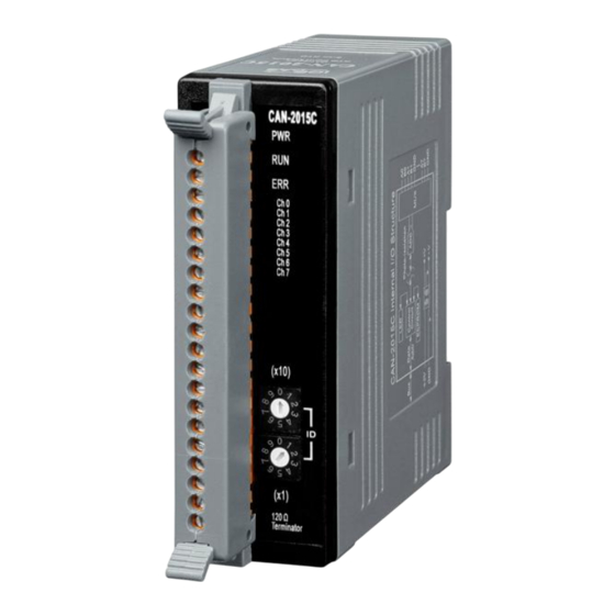
Page 6: Hardware
Hardware Structure (Top View) (Botton View) CAN-2015C User’s Manual (Version 1.0, June/2012) ------------- 6... -
Page 7: Node Id & Baud Rate Rotary Switch
Node ID & Baud Rate Rotary Switch The rotary switches for node ID configure the node ID of the CAN-2015C module. These two switches are for the tens digit and the units digit of node ID. The node ID value of this demo picture is 32. -
Page 8: Led Description
Guard event happened Continuing Light Bus Off The CAN controller is bus off Terminal Resistor LED When the switch of the 120Ω terminal resistor is turned on, the terminal resistor LED will be lightening. CAN-2015C User’s Manual (Version 1.0, June/2012) ------------- 8... -
Page 9: Pin Assignment
PIN Assignment Wire Connection CAN-2015C User’s Manual (Version 1.0, June/2012) ------------- 9... -
Page 10: Application
1017h Heartbeat time UNSIGNED 16 largest sub-index supported for 1018h UNSIGNED 8 “identity object” vender ID UNSIGNED 32 0x0000013C Produce Code UNSIGNED 32 0x00002015 Revision_number UNSIGNED 32 0x00030001 Serial_number UNSIGNED 32 0x6cd3683c CAN-2015C User’s Manual (Version 1.0, June/2012) ------------- 10... - Page 11 Attr Default 1600h Number of entries UNSIGNED 8 1601h Number of entries UNSIGNED 8 1602h Number of entries UNSIGNED 8 … … … … … … 1609h Number of entries UNSIGNED 8 CAN-2015C User’s Manual (Version 1.0, June/2012) ------------- 11...
- Page 12 … … … 1809h Number of entries UNSIGNED 8 COB-ID used by TxPDO UNSIGNED 32 80000000h Transmission type UNSIGNED 8 Inhibit time UNSIGNED 16 … … … Reversed Event timer UNSIGNED 16 CAN-2015C User’s Manual (Version 1.0, June/2012) ------------- 12...
- Page 13 The RTD value of channel 0 INTEGER16 … … … … … The RTD value of channel 7 INTEGER16 RTD Input Global Interrupt Enable Sidx Description Type Attr Default 6423h RTD Input Global Interrupt Trig Boolean Enable CAN-2015C User’s Manual (Version 1.0, June/2012) ------------- 13...
- Page 14 Note: These values are used to define the acceptable RTD change ranges for each RTD channels and may have different range for the physical value because of the settings of the type code. Please refer to the appendix or the type code definition. CAN-2015C User’s Manual (Version 1.0, June/2012) ------------- 14...
-
Page 15: Store And Restore Object
RTD interrupt delta values for channel 0~7 1400h RxPDO1 parameter 1409h RxPDO10 parameter 1600h RxPDO1 mapping information … 1609h RxPDO10 mapping information 1800h TxPDO1 parameter 1809h TxPDO10 parameter 1A00h TxPDO1 mapping information … 1A09h TxPDO10 mapping information CAN-2015C User’s Manual (Version 1.0, June/2012) ------------- 15... -
Page 16: Application Object
0~7, and the range for each RTD type code are listed in Appendix. If the user wants to change the RTD input type, write the type code to the object with index 2004h and subindex 1~8. For example, if the node ID of CAN-2015C is 1, the following command would be used:... -
Page 17: Default Pdo Mapping
Reserved 300h+x Reserved 400h+x Reserved 500h+x Reserved TxPDO mapping list: 180h+x Reserved 280h+x RTD ch0 RTD ch1 RTD ch2 RTD ch3 380h+x RTD ch4 RTD ch5 RTD ch6 RTD ch7 480h+x Reserved CAN-2015C User’s Manual (Version 1.0, June/2012) ------------- 17... -
Page 18: Emcy Communication
00 00 00 00 PDO Data Length Error 00 00 00 00 Request To Reset Node or Communication 00 00 00 00 Upper/Lower limit alarm for Upper limit Lower limit Each channel alarm alarm CAN-2015C User’s Manual (Version 1.0, June/2012) ------------- 18... -
Page 19: Appendix: Type Code Definition
% of FSR +100.00 +000.00 0 to 600 degree Celsius 7FFF 0000 2’s complement HEX +317.28 +100.00 Nickel 120 Engineer Unit +100.00 -080.00 -80 to 100 degree Celsius % of FSR +100.00 -080.00 CAN-2015C User’s Manual (Version 1.0, June/2012) ------------- 19... - Page 20 -200 to 600 degree Celsius 7FFF D556 2’s complement HEX +313.59 +018.49 Pt 100 Engineer Unit +600.00 -200.00 a=0.003916 % of FSR +100.00 -033.33 -200 to 600 degree Celsius 7FFF D556 2’s complement HEX +317.28 +017.14 CAN-2015C User’s Manual (Version 1.0, June/2012) ------------- 20...
Need help?
Do you have a question about the CAN-2015C and is the answer not in the manual?
Questions and answers