
Related Manuals for iDule ID50MB-CL


Summary of Contents for iDule ID50MB-CL
- Page 1 48M CMOS Camera ID50MB-CL (B/W) ID50MC-CL (Color) Technical Manual iDule Corporation...
-
Page 2: Table Of Contents
Table of Contents PAGE Product Outline ............................3 Handling Precautions ........................... 3 Specification ..............................4 3.1. General Specification ............................. 4 3.2. Camera Output Signal Specification ......................... 5 3.3. Spectral Response (Representative Value) ....................... 6 Connector ..............................7 4.1. Camera Link Connector 12226-1100-00PL (3M) ....................7 4.2. -
Page 3: Product Outline
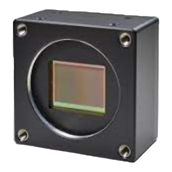
Product Outline ID50MB-CL/ID50MC-CL is a Camera Link interfaced and 48M resolution camera module. 48M pixels CMOS sensor with diagonal length 45.717mm is utilized. Entire pixels can be read out within 1/12.8s at Full Configuration output. Features Global Shutter CMOS sensor is utilized. -
Page 4: Specification
Specification 3.1. General Specification (1) Image Sensor Device type Diagonal length 45.717mm, Global Shutter type (CMOSIS CMV50000) Effective pixel number 7920(H) x 6004(V) Unit cell size 4.6μm(H) x 4.6μm(V) Image circle Φ45.717mm 27.618 36.432 (単位:mm) (2) Video Output Frequency 80.5MHz Pixel Clock 7920(H) x 6004(V) Output effective pixel number... -
Page 5: Camera Output Signal Specification
3.2. Camera Output Signal Specification Effective Video Output 7920(H) × 6004(V) (at Full Frame Scan Mode) Video Output Data LVAL Camera Link (LVDS) Sync Signal Output FVAL DVAL CC2・CC3・CC4 Camera Link (LVDS) (No Function) Camera Control Signal Input (4)Trigger Input Polarity Positive/Negative Selectable (Address 05h) -
Page 6: Spectral Response (Representative Value)
3.3. Spectral Response (Representative Value) ID50MB-CL (B/W) / ID50MC-CL (Color) -
Page 7: Connector
Connector 4.1. Camera Link Connector 12226-1100-00PL (3M) (CN1) Power input Selector switch (Power LED) (SW1) (P2) (P1) Connector (P2) Connector (P1) +12V(PoCL) +12V(PoCL) Yclk- Yclk+ Xclk- Xclk+ 100Ω Terminated SerTC+ SerTC- SerTFG- SerTFG+ CC1- (Trigger IN -) CC1+ (Trigger IN +) CC2+ CC2- Zclk-... -
Page 8: Power Led
4.2. Power LED Camera turns on LED light, when it is supplied electricity from the frame Grabber board. 4.3. 12pin Connector HR10A-10R-12PB (HIROSE) (CN1) IO(5V TTL) +5.0V(VCC) POWER IN(DC+12V) 12pin 100 Ω FVAL Output SN74LVC1G32(TI) Voh:3.8V(Min) Vol:0.55V(Max) FVAL OUT 100 Ω External Trigger Input SN74LVC1G14(TI) (CN1) -
Page 9: Timing Chart
Timing Chart 5.1. Horizontal Synchronous Signals Timing (8Tap Full Configuration) 7912 ~ 0 ~ 7 7919 Video Out Port A 7912 Port B 7913 ・ ・ ・ ・ ・ ・ ・ ・ ・ ・ ・ ・ Port C 7914 Port D 7915 ・ ・ ・ ・ ・ ・ ・ ・ ・ ・ ・ ・ Port E 7916 Port F 7917 ・ ・ ・ ・ ・ ・ ・ ・ ・ ・ ・ ・ Port G 7918 Port H 7919... -
Page 10: Horizontal Synchronous Signals Timing (4Tap Medium Configuration)
5.3. Horizontal Synchronous Signals Timing (4Tap Medium Configuration) 7912 ~ 0 ~ 7 7919 Video Out Port A 7916 Port B 7917 ・ ・ ・ ・ ・ ・ ・ ・ ・ ・ ・ ・ ・ ・ ・ ・ ・ ・ ・ ・ ・ ・ ・ ・ Port C 7918 Port D 7919 ・ ・ ・ ・ ・ ・ ・ ・ ・ ・ ・ ・ ・ ・ ・ ・ ・ ・ ・ ・ ・ ・ ・ ・ LVAL Out DVAL Out 92 CLK Effective Data : 1980 CLK Pixel ... -
Page 11: Image Output Format
5.5. Image output format (1) 8Tap Full Configuration : 12.8fps ID50MB-CL (B/W) 7920 pixel ~ ~ ・・・ ~ 7912 7913 7918 7919 8pixel 8pixel 8pixel ID50MC-CL (Color) 7920 pixel ~ ~ ・・・ ~ 7912 7913 7918 7919 8pixel 8pixel 8pixel (2) 4Tap Medium Configuration :... -
Page 12: Fixed Trigger Shutter Mode
5.6. Fixed Trigger Shutter Mode This is the mode to start exposure with external input trigger signals, and set the exposure time with serial □ commands. Delay time (Exposure Time Delay) from detecting trigger edge in the camera to starting exposure. □... -
Page 13: Pulse Width Trigger Shutter Mode
5.7. Pulse Width Trigger Shutter Mode This is the mode to start exposure with external input trigger signals, and set the exposure time with □ pulse width of the trigger signals. Delay time (Exposure Time Delay) from detecting trigger edge in the camera to starting exposure, and from □... -
Page 14: Partial Scan Mode
Partial Scan Mode 1 partial area can be set by serial commands. □ Partial Scan Setting Data sequence of output video パーシャルスキャン設定 出力画像の並び Partial scan effective lines パーシャルスキャン有効ライン数 ② Partial scan start position パーシャルスキャンスタートポジション (アドレス:40-41) (Address 40-41) Partial scan effective lines パーシャルスキャン有効ライン数... - Page 15 When setting several partial scan areas, please set the start position and effective lines trying not to □ overlap the areas. When setting several areas, please set the areas in the numerial order of start position. □ Entire frame line numbers = V blanking line numbers (44H fixed) + Partial effective lines □...
-
Page 16: Remote Communication
Remote Communication Via camera link cable, the camera can be controlled. Communication Settings Baud Rate :115200bps (fixed) Data :8bit Stop bit :1bit Parity :None :No Control XON / XOFF ・ Send Command Format (Host to Camera) If send a command, set the command and parameter between STX and ETX. command parameter (ASCII code) (02H) -
Page 17: Command Specifications
7.1. Command Specifications 1) Set some values of resister 【Command】 Set : Resister ・・・ Data (Variable-length:max 16 address) Address 【Return Value】 Succeed ・・・ Fail ・・・ 2) Dead pixel correction write area (X,Y) 【Command】 Set : Resister ・・・ Address Data (variable length:max 16 address) 【Return Value】... - Page 18 4) Dead pixel correction read area (X,Y) 【Command】 Get : Resister Address Data acquisitions number 【Return Value】 Succeed ・・・ ・・・ Data( Data length depends on the number of acquisitions ) Fail ・・・ 5) Set User’s data 【Command】 Set : User’s data ・・・...
- Page 19 7) Save all configurations 【Command】 Configuration : Save 【Return Value】 Succeed ・・・ Fail ・・・ 8) Restore all configurations 【Command】 Configuration : Restore 【Return Value】 Succeed ・・・ Fail ・・・ 9) Get a model name 【Command】 Query : Model name 【Return Value】 Succeed ・・・...
- Page 20 11) Get a firmware version 【Command】 Query : Version 【Return Value】 Succeed ・・・ ・・・ Version information (fixed length:8byte) Fail ・・・ 12) Get a detail of error information 【Command】 Query : Error 【Return Value】 Succeed ・・・ Kind Detal Fail ・・・ Kind Detail 0:...
-
Page 21: Control Example
7.2. Control Example 1) How to check trigger shutter mode. ( The command gets a value from address 04) 【Send Command】 Address 04 【Return value form camera】 Data 01 【Receive Return Value】 The camera is working with a trigger shutter mode, because the command received a 01 from the camera. 2) How to check trigger shutter mode. - Page 22 How to set partial scan mode. (The command sets 01 for address 08) 【Send Command】 Address 08 Data 01 【Return value form camera】 【Receive Return Value】 The command finished normally, because the command received ACK from the camera. How to set 01FF for manual shutter. (The command set 01FF for address 24) 【Send Command】...
- Page 23 How to save configurations of a camera. (The command send CS) 【Send Command】 【Return value form camera】 【Receive Return Value】 The command finished normally, because the command received ACK from the camera. How to restore the camera to initial settings. (The command send CR) 【Send Command】...
- Page 24 How to get detail of a communication error. 【Send Command】 Set the address invalid value 【Return value form camera】 【Receive return value】 The command finished abnormally, because the command received ‘NAK’ from the camera. When the command did not finish normally, retry to send command or send to get detail of a detail error command. 【Send Command】...
-
Page 25: Function Setting
Function Setting 8.1. Camera function Register setting (Register setting using serial communication via microcomputer.) Function Address(Hex) Data(Hex) 4Tap Medium 8Tap Full 00: 1/6.4s(OFF) 1/12.8s(OFF) 01: 1/12.8s 1/25s 02: 1/25s 1/50s 03: 1/50s 1/100s 04: 1/100s 1/200s 05: 1/200s 1/400s 06: 1/400s 1/750s 07:... - Page 26 Function Data(Hex) Address(Hex) 00: 8Tap Full Configuration Output mode 01: 4Tap Medium Configuration 00: 8bit output 8Tap, 4Tap Configuration 01: Output bit 10bit output 8Tap, 4Tap Configuration 02: 12bit output 4Tap Configuration LED ON/OFF min:0(0000H) ~ max:767(02FFH) x1.0(0dB) ~ x4.0(+12dB) Gain = (setting value+256) / 256 Manual gain 20-21 LLHH:...
- Page 27 Function Data(Hex) Address(Hex) Full frame : 0(0000H) B/W :min:0(0H) - max:6003(1773FH) Color :min:0(0H) - max:6002(1772H) Partial scan ※(Color) Be sure to set the start position to an even number. 40-41 LLHH: Start position 1 Full frame : 6004(1774H) B/W :min:1(1H) - max:6004(1774H) Color:min:2(2H) - max:6004(1774H) Partial scan ※(Color)
-
Page 28: Dimensions
Dimensions 撮 像 面 ) r i... -
Page 29: Initial Setting
10. Initial Setting Function Address Data Shutter 1/12.8s(OFF) White Balance (Color model) 3200K Trigger Mode Normal (Trigger OFF) Trigger Polarity Positive Trigger Input Partial Scan Mode Full Frame Output mode 8Tap Full configuration Output Data Selection 8bit LED ON/OFF Manual Gain 20-21 0000: Manual Shutter... -
Page 30: Cases For Indemnity (Limited Warranty)
On very rare occasions, however, CMOS pixel defects might be noted with time of usage of the products. Cause of the CMOS pixel defects is the characteristic phenomenon of CMOS itself and IDULE is exempted from taking any responsibilities for them. Should you have any questions on CMOS pixel defects compensation, please contact us.
Need help?
Do you have a question about the ID50MB-CL and is the answer not in the manual?
Questions and answers