
Related Manuals for iDule ID1MB-BRDC-U


Summary of Contents for iDule ID1MB-BRDC-U
- Page 1 1.2Mega CMOS USB Camera ID1MB-BRDC-U (B/W) ID1MC-BRDC-U (COLOR) Technical Manual iDule Corporation...
-
Page 2: Table Of Contents
Table of Contents PAGE Product Outline ............................3 Handling Precautions ........................... 3 Specification ..............................4 3.1.General Specification ............................4 3.2.Camera Output Signal Specification ........................5 3.3.Spectral Response (Representative Value) ......................6 Connector ..............................7 4.1.Connector P1 ..............................7 4.2.Connector CN1 ............................... 7 Timing Chart .............................. -
Page 3: Product Outline
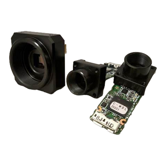
Product Outline ID1MB-BRDC-U/ID1MC-BRDC-U is a USB3.0/2.0 interfaced and 1.2Mega resolution camera module. 1.2Mega pixels CMOS sensor with diagonal length 6.0mm is utilized. Entire pixels can be read out within 1/54s. Features Global Shutter CMOS sensor is utilized. □ Fixed trigger shutter mode is operable. -
Page 4: Specification
Specification 3.1.General Specification (1) Image Sensor Type Diagonal length 6.0mm Global Shutter (OnSemi AR0135) 1284(H) x 962(V) Effective Pixel Number 3.75μm(H) x 3.75μm(V) Cell Size Φ6.0mm (SXGA) Image Circle Φ3.0mm (VGA) Φ1.5mm (QVGA) (2) Video Output Pixel CLK 74.25MHz Frequency SXGA : 1284(H) x 962(V) Output effective pixel number VGA : 644(H) x 482(V) -
Page 5: Camera Output Signal Specification
3.2.Camera Output Signal Specification 3.2.1. USB3.0 / 2.0 (1)Video Output Data Effective Video Output 1284(H) × 962(V) (2)Video Signals White Clip Level (at gain 0dB) Setup Level Under 0Ch Dark Sharding Both horizontal and vertical should be under 00Fh 3.2.2. External Input / Output Low1.4V(max),High3.3V~5.0V (1)Trigger in CN1 : 1pin... -
Page 6: Spectral Response (Representative Value)
3.3.Spectral Response (Representative Value) ID1MB-BRDC-U (B/W) ID1MC-BRDC-U (Color) -
Page 7: Connector
Connector 4.1.Connector P1 USB3.0 Micro B Connector USB Bus Power 4.2.Connector CN1 External input and output connector BM04B-SRSS-TB (JST) PIN No Name Trigger IN Exposure OUT... -
Page 8: Timing Chart
Timing Chart 5.1.USB3.0 Normal Shutter Mode After CMOS sensor is finished to expose, start to translate USB data. USB translate timing is not fixed. 5.2. USB3.0 Fixed Trigger Shutter Mode After CMOS sensor is finished to expose, start to translate USB data. Frame Rate depend on trigger timing and exposure time. -
Page 9: Usb2.0 Normal Shutter Mode
5.3.USB2.0 Normal Shutter Mode After CMOS sensor is finished to expose, start to translate USB data. USB translate timing is not fixed. 5.4.USB2.0 Fixed Trigger Shutter Mode After CMOS sensor is finished to expose, start to translate USB data. Frame Rate depend on trigger timing and exposure time. USB translate timing is not fixed. -
Page 10: Output Format
5.5.Output Format UVC (YUV-RAW) ID1MB-BRDC-U ID1MC-BRDC-U Y8 (RAW) ID1MB-BRDC-U ID1MC-BRDC-U... -
Page 11: Fixed Trigger Shutter Mode
5.6.Fixed Trigger Shutter Mode This is the mode to start exposure with external input trigger signals, and set the exposure time with serial □ commands. Delay time (Exposure Time Delay) from detecting trigger edge in the camera to starting exposure is as below. □... -
Page 12: Scan Mode
Scan Mode 6.1. Partial Scan Mode In SXGA and VGA modes, the frame rate can be increased by limiting the vertical scan area. □ Set the mode and start position using UVC Commit Control and communication commands. □ Partial Scan Setting Partial Scan Area 1/2, 1/4, 1/8 (by UVC Commit Control) Partial Scan Start Position... - Page 13 Please set the start position 2 x n. □ Start position + Effective Line number <= 962 Flame Total Lines Time □ Normal Shutter Mode = V blanking line number 27H fixed) + Partial Scan Effective line numbers Fixed Trigger Shutter Mode = Shutter Speed (s) + V blanking line number 54H fixed) +...
-
Page 14: Binning Mode
Binning Mode Two horizontal pixels and two vertical pixels are added to one pixel for output. □ The number of pixels (transfer data amount) can be reduced without changing the angle of view. □ □ Frame rate is the same as all pixel output. □... -
Page 15: Qvga Mode
QVGA Mode Cut out QVGA 324 x 242 pixels from all pixels and output. □ There are fewer lines and the frame rate goes up to 167.28fps. □ Select 324 x 242 in UVC Commit Control and set to QVGA mode. □... -
Page 16: Uvc Extension Units (Usb) Function
10. UVC Extension Units (USB) Function Set the function with the SetVal () and GetVal () functions in the software development kit. 11. Function Setting Function Address Data(Hex) (Hex) Gain Mode 12dB Manual (Address20-21) RGB Manual Gain (*1) (R Address 28-29, B Address2 A-2B, G Address 2C-2D) Gain setting is possible for each RGB. - Page 17 Function Address Data(Hex) (Hex) USB Mode Auto USB3.0 / 2.0 is automatically detected and an image is output. USB3.0 fixed USB2.0 fixed Exposure Signal Positive Negative Low fixed High fixed Binning Mode UVC Commit Control ( VGA Mode: ON) Manual Gain 20-21 LLHH: min:0(0H) - max:144(90H)
- Page 18 Function Address Data(Hex) (Hex) Vertical Start Position 40-41 LLHH: UVC Commit Control Partial Scan / VGA / QVGA Mode min:0(0H) - max:900(384H) Horizontal Start Position 42-43 LLHH: UVC Commit Control VGA Mode / QVGA Mode min:0(0H) - max:960(3C0H)
-
Page 19: Dimensions
12. Dimensions (mm) -
Page 20: Initial Setting
13. Initial Setting Function Address Data Gain Mode Shutter Mode (OFF) *1 Trigger Mode Normal (Trigger OFF) Trigger Input Camera Output Mode UVC YUV-RAW USB Mode Auto Exposure Signal Negative Binning Mode Manual Gain 20-21 0000: Manual Shutter 24-23 0000: Shutter(OFF) Manual White Balance R (Color model) 28-29... -
Page 21: Cases For Indemnity (Limited Warranty)
On very rare occasions, however, CMOS pixel defects might be noted with time of usage of the products. Cause of the CMOS pixel defects is the characteristic phenomenon of CMOS itself and IDULE is exempted from taking any responsibilities for them. Should you have any questions on CMOS pixel defects compensation, please contact us.
Need help?
Do you have a question about the ID1MB-BRDC-U and is the answer not in the manual?
Questions and answers