
Related Manuals for iDule ID50MB-OPT


Summary of Contents for iDule ID50MB-OPT
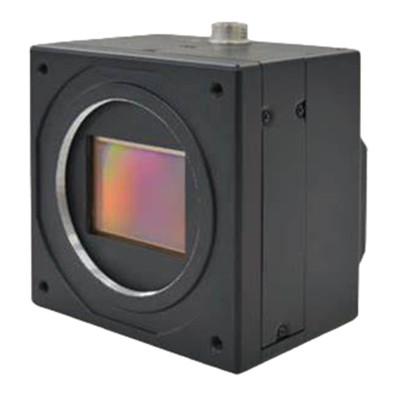
- Page 1 50M CMOS Camera ID50MB-OPT (MONO) ID50MC-OPT (COLOR) Technical Manual iDule Corporation...
-
Page 2: Table Of Contents
Table of Contents PAGE Product Outline ............................... 3 Handling Precautions ............................. 3 Specification ..............................4 3.1.General Specification ............................4 3.2.Camera Output Signal Specification ........................5 3.3.Spectral Response (Representative Value) ......................6 Connector ................................ 7 4.1.LC Duplex AAL-0386 (Adamant) ......................... 7 4.2.Power LED ................................ -
Page 3: Product Outline
Product Outline ID50MB-OPT/ID50MC-OPT is a Opt-C:Link interfaced and 50M resolution camera module. 50M pixels CMOS sensor with diagonal length 45.717 mm is utilized. Entire pixels can be read out within 1/25s. Features Global Shutter CMOS sensor is utilized. □ Fixed trigger shutter mode, pulse width trigger shutter mode are operable. -
Page 4: Specification
Specification 3.1.General Specification (1) Image Sensor Type Diagonal length 45.717mm, Global Shutter (AMS CMV5000) Effective Pixel Number 7920(H) x 6004(V) Cell Size 4.6μm(H) x 4.6μm(V) Image Circle Φ45.717mm (2) Video Output Frequency Pixel Clock 78.4MHz 7920(H) x 6004(V) Output Effective Pixel number Output Timing 25 fps 518(H) x 6048(V) with blancking... -
Page 5: Camera Output Signal Specification
3.2.Camera Output Signal Specification Effective Video Output 7920(H) × 6004(V) (at Full Frame Scan Mode) Video Output Data LVAL Opt-C:Link Sync Signal Output FVAL DVAL (3)Trigger Input Polarity Positive/Negative Selectable (Address 05) Opt-C:Link Trigger input 12pin connector 12pin connector 11pin (5V TTL) Trigger input 1HD:6.607us(Min) ~... -
Page 6: Spectral Response (Representative Value)
3.3.Spectral Response (Representative Value) Mono(ID50MB-OPT) / Color(ID50MC-OPT) -
Page 7: Connector
Connector 4.1.LC Duplex AAL-0386 (Adamant) ID50MB/ID50MC-OPT have 2Lane optical connectors. They need 2 optical cables. And you can use right side connectors only. (Left side is optional) 4.2.Power LED Status Link Lighting No Link Blinking Lights Out No Connect Cable / Camera Power 4.3.12pin Connector HR10A-10R-12PB (Hirose)(CN1) Name IO(5V TTL) -
Page 8: Timing Chart
Timing Chart 5.1.Horizontal Synchronous Signals Timing Lane1 Port 0 ~ Port 7 1 ~ 8 7905 ~ 7912 ・ ・ ・ ・ ・ ・ ・ ・ ・ ・ ・ ・ ・ ・ ・ ・ ・ ・ ・ ・ ・ ・ ・ ・ Lane2 Port 0 ~ Port 7 9 ~ 16... -
Page 9: Video Output Format
5.3. Video Output Format 7920 pixel ~ ~ ・・・ ~ 7913 7914 7919 7920 Lane1 Lane2 Lane2 8pixel 8pixel 8pixel 7920 pixel ~ ~ ・・・ ~ 7913 7914 7919 7920 Lane1 Lane2 Lane2 8pixel 8pixel 8pixel... -
Page 10: Fixed Trigger Shutter Mode
5.4.Fixed Trigger Shutter Mode □ This is the mode to start exposure with external input trigger signals, and set the exposure time with serial commands. □ Delay time (Exposure Time Delay) from detecting trigger edge in the camera to starting exposure is max 18.312us. Max 1HD :... -
Page 11: Pulse Width Trigger Shutter Mode
5.5.Pulse Width Trigger Shutter Mode This is the mode to start exposure with external input trigger signals, and set the exposure time with □ pulse width of the trigger signals. Delay time (Exposure Time Delay) from detecting trigger edge in the camera to starting exposure. □... -
Page 12: Partial Scan Mode
Partial Scan Mode □ 1 partial area can be set by serial commands. Example : 1 partial area to be set. Video Out FVAL LVAL ① ② ③ V Blanking : 44H (fixed) ① Partial Area : 20H ② Frame Total Line Number : 64H (①+②) ③... - Page 13 Entire frame line numbers = V blanking line numbers (44H fixed) +Partial effective lines □ Note that “Sum total of partial effective line numbers (expect V blanking lines) < 6004” should be met. Frame rate = 1 / (Entire frame line numbers × Time for 1 line) □...
-
Page 14: Remote Communication
Remote Communication Via camera link cable, the camera can be controlled. Communication Settings Baud Rate :115200bps (fixed) Data :8bit Stop bit :1bit Parity :None :No Control XON / XOFF ・ Send Command Format (Host to Camera) If send a command, set the command and parameter between STX and ETX. command parameter (ASCII code) (02H) -
Page 15: Command Specifications
7.1.Command Specifications 1) Set some values of resister 【Command】 Set : Resister ・・・ Data (Variable-length:max 16 address) Address 【Return Value】 Succeed ・・・ Fail ・・・ 2) Get some value of resister 【Command】 Get : Resister Address Number of data acquisition (optional) 【Return value】... - Page 16 3) Set User’s data 【Command】 Set : User’s data ・・・ Table No. User’s data (fixed length :16byte) (0~3) 【Return Value】 Succeed ・・・ Fail ・・・ 【Remarks】 The commands, sets free data on the specified register, and can use 4 tables (1 table : 16 characters). 4) Get User’s data 【Command】...
- Page 17 5) Save all configurations 【Command】 Configuration : Save 【Return Value】 Succeed ・・・ Fail ・・・ 6) Restore all configurations 【Command】 Configuration : Restore 【Return Value】 Succeed ・・・ Fail ・・・ 7) Get a model name 【Command】 Query : Model name 【Return Value】 Succeed ・・・...
- Page 18 9) Get a firmware version 【Command】 Query : Version 【Return Value】 Succeed ・・・ ・・・ Version information (fixed length:8byte) Fail ・・・ 10) Get a detail of error information 【Command】 Query : Error 【Return Value】 Succeed ・・・ Kind Detal Fail ・・・ Kind Detail 0:...
- Page 19 11) Dead pixel Correction (Coordinate position) Write 【Command】 Set : Register ・・・ Address Data (Variable-length:max 16 address) 【Return Value】 Succeed ・・・ Fail ・・・ 12) Dead pixel Correction (Coordinate position) Read 【Command】 Set : Register ・・・ Address Data 【Return Value】 Succeed ・・・...
-
Page 20: Control Example
7.2.Control Example 1) How to check trigger shutter mode. ( The command gets a value from address 04) 【Send Command】 Address 04 【Return value form camera】 Data 01 【Receive Return Value】 The camera is working with a trigger shutter mode, because the command received a 01 from the camera. 2) How to check trigger shutter mode. - Page 21 How to set partial scan mode. (The command sets 01 for address 08) 【Send Command】 Address 08 Data 01 【Return value form camera】 【Receive Return Value】 The command finished normally, because the command received ACK from the camera. How to set 01FF for manual shutter. (The command set 01FF for address 24) 【Send Command】...
- Page 22 How to save configurations of a camera. (The command send CS) 【Send Command】 【Return value form camera】 【Receive Return Value】 The command finished normally, because the command received ACK from the camera. How to restore the camera to initial settings. (The command send CR) 【Send Command】...
- Page 23 How to get detail of a communication error. 【Send Command】 Set the address invalid value 【Return value form camera】 【Receive return value】 The command finished abnormally, because the command received ‘NAK’ from the camera. When the command did not finish normally, retry to send command or send to get detail of a detail error command. 【Send Command】...
-
Page 24: Function Setting
Function Setting Function Address(Hex) Data(Hex) 1/25s(OFF) 1/50s 1/100s 1/200s 1/400s 1/800s 1/1500s 1/2500s Shutter 1/4000s 1/6500s 1/8000s 1/9000s 1/10000s 1/11000s 1/12000s Manual Shutter (Address24-25) THRU White Balance 3200K (Color model) THRU(Spare) Manual White Balance Normal Shutter Mode (Trigger OFF) Trigger Mode Fixed Trigger Shutter Mode(Address01:Shutter Speed) Pulse Width Trigger Shutter Mode Positive... - Page 25 Function Data(Hex) Address(Hex) LED ON/OFF Manual Gain 20-21 LLHH: min:0(0000H) - max:767(2FFH) 0: x1(0dB), 767: x4(+12dB) Manual Shutter 24-25 LLHH: min:0(0H) - max:6003(1773H) Shutter time = 74.893us + (6004 - (setting value))×6.607us min:0=39.743ms, max:6003=81.500us Manual White Balance R 28-29 LLHH: min:0(0H) - max:767(2FFH) 0: x1(0dB), 767: x4(+12dB) (Color)
- Page 26 Function Address(Hex) Data(Hex) 40-41 LLHH: Full Frame Scan : 0(0000H) Mono : min:0(0000H) - max:6003(1773H) Partial Scan Color : S min:0(0H) - max:6002(1772H) Start Position 50-51 LLHH: Full Frame Scan : 6004(1774H) Mono :min:1(1H) - max:6004(1774H) Partial Scan Color :min:2(2H) - max:6004(1774H) Effective Line ※...
-
Page 27: Dimensions
Dimensions 深 サ 撮 像 面 深 サ 深 サ ) r i 深 サ... -
Page 28: Initial Setting
10. Initial Setting Function Address Data Shutter 1/25s(OFF) White Balance (Color) 3200K Trigger Mode Normal (Trigger OFF) Trigger Polarity Positive Trigger Input CC1(OPT-C) Partial Scan Mode Full Frame LED ON/OFF Manual Gain 20-21 0000: Manual Shutter 24-25 0000: Shutter (OFF) Manual White Balance R (Color) 28-29 0000:... -
Page 29: Dead Pixel Correction Function
11. Dead Pixel Correction Function Max 32 pixels can be corrected in camera. Function Data(Hex) Address(Hex) min:0(0H) - max:7919(1EEFH) X coordinate cursor indication 17A-17B LLHH: Correction OFF : 65535(FFFFH) min:0(0H) - max:6003(1773H) Y coordinate cursor indication 17C-1’D LLHH: Correction OFF : 65535(FFFFH) Function Data(Hex) Address(Hex) - Page 30 Function Data(Hex) Address(Hex) X coordinate No.16 1C0-1C1 Y coordinate No.16 1C2-1C3 X coordinate No.17 1C4-1C5 Y coordinate No.17 1C6-1C7 X coordinate No.18 1C8-1C9 Y coordinate No.18 1CA-1CB X coordinate No.19 1CC-1CD Y coordinate No.19 1CE-1CF X coordinate No.20 1D0-1D1 Y coordinate No.20 1D2-1D3 X coordinate No.21 1D4-1D5...
- Page 31 <Setting Example> Dead Pixel position ---> Coordinate (X:6000 , Y:1234)
-
Page 32: Cases For Indemnity (Limited Warranty)
On very rare occasions, however, CMOS pixel defects might be noted with time of usage of the products. Cause of the CMOS pixel defects is the characteristic phenomenon of CMOS itself and IDULE is exempted from taking any responsibilities for them. Should you have any questions on CMOS pixel defects compensation, please contact us.
Need help?
Do you have a question about the ID50MB-OPT and is the answer not in the manual?
Questions and answers