Table of Contents
Advertisement
Forma Scientific, Inc.
P.O. Box 649
Marietta, Ohio 45750
U.S.A.
Telephone: (740) 373-4763
Telefax: (740) 373-4189
________________________________________
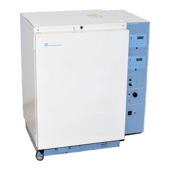
Models
3546 and 3548
Water Jacketed
Incubator
Operating Manual
Manual No. 7053546
Rev. 0
Read this Instruction Manual
Failure to read, understand and follow the instructions in this manual may result in
damage to the unit, injury to operating personnel and poor equipment performance.
Advertisement
Table of Contents

Subscribe to Our Youtube Channel
Related Manuals for Forma Scientific 3546


Summary of Contents for Forma Scientific 3546
- Page 1 P.O. Box 649 Marietta, Ohio 45750 U.S.A. Telephone: (740) 373-4763 Telefax: (740) 373-4189 ________________________________________ Models 3546 and 3548 Water Jacketed Incubator Operating Manual Manual No. 7053546 Rev. 0 Read this Instruction Manual Failure to read, understand and follow the instructions in this manual may result in...
- Page 2 In no event shall Forma Scientific, Inc. be held liable for any damages, direct or incidental, arising out of or related to the use of this manual. When contacting the factory regarding this unit, have the model, serial number and date of purchase available.
-
Page 3: Table Of Contents
Forma Scientific, Inc.___________________________________________________Contents Table of Contents Section 1 - Receiving 1.1 Preliminary Inspection ................. 1-1 1.2 Visible Loss or Damage ............... 1-1 1.3 Responsibility for Shipping Damage ............ 1-1 Section 2 - Unpacking List 2.1 Unpacking List..................2-1 Section 3 - Installation and Start-Up 3.1 Location .................... - Page 4 Forma Scientific, Inc.___________________________________________________Contents 3.15 Connecting the gas supply when not using the Gas Guard ....3-13 3.16 Zeroing the CO 2 Controller..............3-14 3.17 Setting the CO 2 Content ..............3-15 Section 4 - Operation 4.1 Operation ..................... 4-1 4.2 Overview of Humidification and CO 2 ..........4-1 4.3 Control Panel ..................
- Page 5 Forma Scientific, Inc.___________________________________________________Contents Section 5 - Routine Maintenance 5.1 Installing The Decontamination Kit ............. 5-1 5.2 Disinfecting the Incubator Interior ............5-3 5.3 Cleaning the Cabinet Exterior .............. 5-4 5.4 Draining the Water Jacket ..............5-4 5.5 Changing the CO 2 Filter ..............5-5 5.6 CO 2 Test Instruments ................
- Page 6 Forma Scientific, Inc.___________________________________________________Contents Section 8 - Parts List Section 9 - Schematics Section 10 - Warranty Information...
-
Page 7: Section 1 - Receiving
Inc. ends when the merchandise is loaded onto the carrier's vehicle. On F.O.B. Destination shipments, Forma Scientific's and the carrier's responsibility ends when your Receiving Department personnel sign a free and clear delivery receipt. Whenever possible, Forma Scientific, Inc. will assist in settling claims for loss or in- transit damage. -
Page 8: Section 2 - Unpacking List
Forma Scientific, Inc.________________________________________________Unpacking Section 2 - Unpacking List 2.1 Unpacking List Remove packing box from incubator. If the unit is to be moved by fork lift, leave the incubator on the skid until it has been moved to its designated location. A plastic bag containing the following accessories is packed inside the incubator: Qty. -
Page 9: Section 3 - Installation And Start-Up
Before installing the duct sheets and the shelves, remove the clear plastic film from the shelf brackets and duct sheets. Forma Scientific, Inc. recommends disinfecting all interior surfaces (including both door gaskets). Rinse the surfaces with sterile distilled water (50K Ohm to 1 Meg Ohm). -
Page 10: Installing The #6 Neoprene Stopper (Access Port)
Forma Scientific, Inc.__________________________________________Installation/Start-up 3.3 Installing the #6 Neoprene Stopper (Access Port) Open the incubator outer door and inner glass door. Locate the opening in the top left corner of the interior chamber. Place the beveled end of the stopper in the opening. - Page 11 Forma Scientific, Inc.__________________________________________Installation/Start-up Installing the Shelf Bracketrs and Duct Sheets Figure 3-1...
-
Page 12: Installing The Duct Sheets
Forma Scientific, Inc.__________________________________________Installation/Start-up 3.5 Installing the Duct Sheets (Refer to Figure 3-1) Note: The left duct sheet has large notches in both top and bottom edges. The right duct sheet has a single notch in the top edge only. Carefully put the right duct sheet into the incubator chamber with the flanges toward the wall. -
Page 13: Connecting The Incubator To A Power Source
Specification section or Electrical Schematics in the back of this manual for specific power requirements. Note: Forma Scientific, Inc. recommends that the incubator be connected to a separate electrical circuit. 3.9 Preparing the Incubator for Filling 450 ml of rust inhibitor was placed in the water jacket before the incubator was shipped. - Page 14 Forma Scientific, Inc.__________________________________________Installation/Start-up Turn the incubator power switch ON. The ADD WATER warning light and audible alarm will come on. Pressing the SET/SILENCE button on the alarm panel will silence the audible alarm Remove the adjusting screwdriver from the front of the control panel by pulling out the black knob beneath the Sample Port.
-
Page 15: Filling The Water Jacket
Forma Scientific, Inc.__________________________________________Installation/Start-up Press the CO 2 SET/SILENCE button and rotate the CO 2 set screw until the display reads 00.0. (Refer to Figure 3-6 for locations of the SET/SILENCE button and set screw.) 3.10 Filling the Water Jacket There are two methods of filling the water-jacket. -
Page 16: Tap Fill Method
Forma Scientific, Inc.__________________________________________Installation/Start-up Add one additional quart (one liter) of distilled water. The incubator is now properly filled. Remove the tubing from the fill fitting and replace the plastic protective cap. Note: Water seepage may occur from vent hole when chamber temperature increases. -
Page 17: Filling The Humidity Reservoir Or Pan
Forma Scientific, Inc.__________________________________________Installation/Start-up Turn the water off immediately when the ADD WATER alarm light goes out. Using the funnel, add an additional quart (one liter) of distilled water. Remove vinyl tubing and reinstall the plastic protective cap. 3.11 Filling the Humidity Reservoir or Pan Do not use plastic pans for humidification as they will have an unpredictable effect on humidity and O 2 /CO 2 levels in the incubator. -
Page 18: Setting The Chamber Temperature
Forma Scientific, Inc.__________________________________________Installation/Start-up When installing the humidity pan, exercise care to avoid tearing the inner door gasket. 3.12 Setting the Chamber Temperature (Refer to Figure 3-4) Before the initial temperature setting is made, push in on the PUSH TO SET button on the Alarm Monitor Module. - Page 19 Forma Scientific, Inc.__________________________________________Installation/Start-up Temperature and Alarm Monitor Module Figure 3-4 3-11...
-
Page 20: Connecting The Optional Gas Guard
30 PSIG to monitor actual input pressure to the incubator injection system. A suitable two-stage pressure regulator is available from Forma Scientific, Inc., Stock #965010. Supply pressure lower than 13.5 PSIG will cause improper operation of the gas guard and may cause nuisance alarms. -
Page 21: Connecting The Gas Supply When Not Using The Gas Guard
Forma Scientific, Inc.__________________________________________Installation/Start-up 3.15 Connecting the Gas Supply when not using the Gas Guard (Refer to Figure 3-6) If the gas guard is not to be used, the gas supply must be connected to the CO 2 inlet. To provide for the most economical use of CO 2 , a main supply of liquid CO 2 is recommended. -
Page 22: Zeroing The Co 2 Controller
Forma Scientific, Inc.__________________________________________Installation/Start-up 3.16 Zeroing the CO 2 Controller (See Figure 3-7) This adjustment is made using the CO 2 gas content of ambient air (0.03%), the most accurate standard available. Never use a FYRITE or other analyzer for this adjustment. The adjustment must be made on initial start-up, and it must also be made if a change in the humidification of the incubator is required. -
Page 23: Setting The Co 2 Content
Forma Scientific, Inc.__________________________________________Installation/Start-up Check the CO 2 at the Desired Setpoint Allow the incubator to reach setpoint and control (inject light will cycle) for a minimum of 30 minutes. Check the CO 2 level with a FYRITE until two consecutive readings agree. If the FYRITE and display are not within plus or minus 1.0%, consult the factory. -
Page 24: Section 4 - Operation
Forma Scientific, Inc.__________________________________________________Operation Section 4 - Operation 4.1 Operation The water jacket is filled with 11.5 gallons (43.5 liters) of water through the fill fitting located on the front of the unit. The water is then warmed by the chamber heater, providing very stable heating of the incubator chamber. - Page 25 Forma Scientific, Inc.__________________________________________________Operation When monitoring the effects of CO 2 , absolute humidity must be held constant so any change in thermal conductivity is caused only by a change in the CO 2 concentration. Under the worst circumstances, a change in absolute humidity could cause such a significant change in thermal conductivity that the controller could shift the CO 2 content by as much as 4%.
-
Page 26: Control Panel
Forma Scientific, Inc.__________________________________________________Operation 4.3 Control Panel (Figure 4-2) Fill Fitting and Vent Hole The fill fitting is located on the center front of the unit, directly above the door. This fitting is to facilitate filling of the water jacket without having to move the unit. -
Page 27: Variable/37°C Switch, Temp Control And Heater Pilot Light
Forma Scientific, Inc.__________________________________________________Operation Variable/37°C Switch, Temp Control and Heater Pilot Light When the Variable/37°C switch is set to the 37°C (up) position, chamber temperature will automatically be maintained at +37°C. If necessary, the 37°C control can be calibrated using the calibration screw located at the lower left side of the temperature control dial. -
Page 28: Audible Co 2 Alarm And Pilot Light
Forma Scientific, Inc.__________________________________________________Operation Control Module Figure 4-3 Audible CO 2 Alarm and Pilot Light The audible CO 2 alarm and pilot light are activated when the percent CO 2 deviates from setpoint by plus or minus 1% (nominal) for longer than approximately four minutes. -
Page 29: Co 2 Inject Light
Forma Scientific, Inc.__________________________________________________Operation Figure 4-4 Alarm Disable Switch on the CO 2 Control Module CO 2 Inject Light The CO 2 inject light is activated whenever there is a demand for CO 2 to meet setpoint requirements. Since the CO 2 inject light is independent of the CO 2 alarm, it will continue to signal a need for CO 2 when the CO 2 alarm is set to either the defeat or silence position. -
Page 30: Alarm/Monitor Module
Forma Scientific, Inc.__________________________________________________Operation The CO 2 zero adjustment is used for zeroing the CO 2 controller to specific control conditions. It is the only user calibration adjustment on the CO 2 module. All internal adjustments are for qualified service personnel only. - Page 31 REMOTE ALARM RELAY WIRING DIAGRAM When the CONTROL switch on the gas guard is turned off the indicator light will be extinguished and the audible alarm will be silenced. The built-in alarm relay on the Model 3546, however, remains active. Figure 4-7...
-
Page 32: Recorder Output
Recorder Output Jack 4.8 (Optional) Gas Guard, Stock #190410 (Refer to Figure 4-9) Forma Scientific's stock # 190410 built-in Gas Guard is a monitoring and switching device for incubator gas supplies. The unit monitors a two cylinder gas supply. When the active supply tank is depleted,... -
Page 33: Control Switch
Forma Scientific, Inc.__________________________________________________Operation Control Switch The CONTROL switch controls power to the gas guard control circuit board. The yellow LEDs on the front panel designate which tank is active and indicate the unit is receiving power. Silence Switch The SILENCE switch silences the alarm and selects the alternate tank. -
Page 34: Section 5 - Routine Maintenance
Forma Scientific, Inc.________________________________________________Maintenance Section 5 - Routine Maintenance 5.1 Installing the Decontamination Kit... -
Page 37: Disinfecting The Incubator Interior
Forma Scientific, Inc.________________________________________________Maintenance 5.2 Disinfecting the Incubator Interior Use an appropriate disinfectant. All articles and surfaces to be disinfected must be thoroughly cleaned and rough dried. Danger: Alcohol, even a 70% solution, is volatile and flammable. Use it only in a well ventilated area that is free from open flame. -
Page 38: Cleaning The Cabinet Exterior
Forma Scientific, Inc.________________________________________________Maintenance After complete decontamination, it is recommended that the incubator be run and tested before placing any valuable contents inside the incubator chamber. 5.3 Cleaning the Cabinet Exterior The incubator exterior may be cleaned with soap and water and a general use laboratory disinfectant. -
Page 39: Changing The Co 2 Filter
Forma Scientific, Inc.________________________________________________Maintenance 5.5 Changing the CO 2 Filter (Qualified Service Personnel Only) Note: Under conditions of normal use, and dependent upon the purity of gas being used, the CO 2 filter should be serviceable for about five years. If the CO 2 filter becomes clogged, replace it with Forma stock #770001. -
Page 40: Section 6 - Service
Forma Scientific, Inc._____________________________________________Service Section 6 - Service 6.1 General Troubleshooting Symptom Possible Cause • Problem 1: Pilot lights not on. Readouts Unit unplugged, or main power switch not on. • are dark. CO 2 power switch is on. Circuit breaker tripped. - Page 41 Forma Scientific, Inc._____________________________________________Service Symptom Possible Cause Problem 7: Digital CO 2 display and • Alarm is disabled. • FYRITE read more than 1% different from Defective alarm circuit. • setpoint. CO 2 alarm not on. Defective CO 2 sampler or control.
- Page 42 Forma Scientific, Inc._____________________________________________Service Symptom Possible Cause • Problem 12: CO 2 setpoint cannot be Defective CO 2 control. changed. • Problem 13: Unit cannot be zeroed. Defective CO 2 potentiometer. • Defective zero control. • Defective CO 2 Sensor. •...
-
Page 43: Co 2 Control Module Calibration
Forma Scientific, Inc._____________________________________________Service 6.2 CO 2 Control Module Calibration These calibration procedures will be necessary only under the following conditions. DO NOT calibrate the incubator for any other reasons! ♦ After the CO 2 controller is replaced. ♦ After the CO 2 sensor is replaced. -
Page 44: Stabilizing The Incubator
Forma Scientific, Inc._____________________________________________Service CO 2 Control Module showing the Extender Card and Span Adjustment Pot Location Figure 6-1 a. Stabilizing the Incubator at operating temperature and humidity with no CO 2 in the chamber. Turn OFF the CO 2 supply at the source. -
Page 45: Adjusting The Span Pot
Forma Scientific, Inc._____________________________________________Service Side View of the CO 2 Control Module Figure 6-2 c. Adjusting the Span Pot (Refer to Figure 6-2) Turn ON the CO 2 at the supply. Turn the CO 2 setpoint to 10%. Allow the CO 2 to stabilize at 10% on the readout and control (inject light will cycle) for a minimum of 15 minutes. -
Page 46: Re-Checking The Zero Adjustment
Forma Scientific, Inc._____________________________________________Service d. Re-checking the Zero Adjustment Turn OFF the CO 2 at the supply. Open both doors wide for 45 seconds. Close the doors, and allow a minimum of 15 minutes for the incubator to stabilize and assure a zero CO 2 condition in the chamber. -
Page 47: 37°C Control Calibration
Forma Scientific, Inc._____________________________________________Service 6.3 37°C Control Calibration If the digital display indicates a temperature other than 37°C when the chamber temperature has stabilized and the temperature select switch is set to 37°C, it may be necessary to calibrate the adjustment. -
Page 48: Replacing The Triac
Forma Scientific, Inc._____________________________________________Service After the sensor has been replaced, calibrate the CO 2 controller according to the instructions in Section 6.2. 6.5 Replacing the Triac (Refer to Wiring Diagram 140179-71-0-D) Turn the incubator off and disconnect it from the power source. -
Page 49: Replacing The Temperature Control
Forma Scientific, Inc._____________________________________________Service 6.7 Replacing the Temperature Control (Refer to Wiring Diagram, 140179-71-0-D) Turn the incubator off and disconnect it from the power source. Remove the screws securing the right side access panel. Remove the panel and set aside. Remove the temperature control knob by loosening the two Allen head screws recessed in the knob. -
Page 50: Replacing The Circuit Breaker
Forma Scientific, Inc._____________________________________________Service 6.9 Replacing the Circuit Breaker Turn the incubator off and disconnect it from the power source. Remove the screws securing the right side access panel. Remove the panel and set aside. Remove the two nuts securing the circuit breaker mounting plate to the control panel. -
Page 51: Replacing The 0.3 Amp Fuse
Forma Scientific, Inc._____________________________________________Service Cut the wires to the defective thermistor, making note of the connections. Attach the new thermistor using the electrical in-line connectors. Install the new thermistor by reversing the above procedure. Take care not to damage the probe tip and make sure that the probe is fully extended in the sheath. - Page 52 Forma Scientific, Inc._____________________________________________Service Remove the four wing nuts that secure the blower mounting plate to the incubator ceiling. Pull the blower motor assembly down into the chamber area. Remove and save the upper blower wheel/blower blade. Cut the tie wrap(s) securing the blower wires to the blower shield plate.
-
Page 53: Fuse Chart
Forma Scientific, Inc._____________________________________________Service 6.14 Fuse Chart Fuse Manufacturer’s Part No. Amp Rating Rupture Speed Control Buss MDL-3/10 0.3 Amp Time Lag 230VAC Buss MDL-3 3.0 Amp Time Lag (3548 only) 6-14... -
Page 54: Section 7 - Features, Specifications And Accessories
Forma Scientific, Inc.______________________________Specifications/Accessories Section 7 - Features, Specifications and Accessories Models 3546/3548 7.1 Construction • Fiberglass insulation combines with the water jacket to form triple-wall protection of the chamber. • Smooth, seam-welded stainless steel interior provides a crevice-free chamber, reducing contamination. -
Page 55: Temperature Control
Forma Scientific, Inc.______________________________Specifications/Accessories 7.3 Temperature Control • Chamber temperature is constantly displayed on easy-to-read LCD. • Independent, electronic, dual temperature controller maintains chamber temperature at a fixed +37 o C or adjustable from +5 o C above ambient to +60 o C. - Page 56 Stock # Electrical Blower Wheel Replacement Kit 90247 Electropolished Stainless Steel Shelf 224140 3546: 90-130 VAC, 1 PH, 50/60 HZ, 4.2 FLA Stainless Steel Humidification Pan Kit 237001 Disposable Microbiological Filter 770001 3548: 180-260 VAC, 1 PH, 50/60 HZ, 2.6 FLA...
- Page 57 Forma Scientific, Inc.______________________________Specifications/Accessories Accessories Description Stock # Blower Wheel Replacement Kit 90247 Electropolished Stainless Steel Shelf 224140 Stainless Steel Humidification Pan Kit 237001 Disposable Microbiological Filter 770001 Tissue Culture Shelf 500171 Stacking Adapter 90265 Floor Stand 505097 Built-In Gas Guard...
- Page 58 Forma Scientific, Inc._______________________________________________Parts Section 8 - Parts List Stock # Description 770001 CO 2 Disposable Filter 250085 CO 2 Solenoid Valve 12VDC, 3W 300164 Over Temp Relay 431142 Four Sided Molded Magnetic Gasket 400296 Silicon Feather Gasket 230094 Glass Fuse .3A (Slow-Blow Type)
- Page 59 Forma Scientific, Inc.__________________________________________Schematics Section 9 - Schematics...
- Page 60 Forma Scientific, Inc.__________________________________________Schematics...
- Page 61 Forma Scientific, Inc.__________________________________________Schematics...
Need help?
Do you have a question about the 3546 and is the answer not in the manual?
Questions and answers