Table of Contents
Advertisement
Quick Links
Forma Scientific, Inc.
Millcreek Road, P.O. Box 649
Marietta, Ohio 45750
U.S.A.
_______________________________________
3950 and 3951
Manual No. 7003950
Failure to read, understand and follow the instructions in this manual may result in
damage to the unit, injury to operating personnel and poor equipment performance.
CAUTION: All internal adjustments and maintenance
must be performed by qualified service personnel.
*Refer to listing of models on page iv.
Telephone: (740) 373-4763
Telefax: (740) 373-4189
Models:
Reach-In CO
29 cu ft capacity
Read This Instruction Manual!
Incubator
2
Rev. 3
Refer to the serial tag on the
rear cover of this manual
Advertisement
Table of Contents

Subscribe to Our Youtube Channel
Related Manuals for Forma Scientific 3950


Summary of Contents for Forma Scientific 3950
- Page 1 Millcreek Road, P.O. Box 649 Marietta, Ohio 45750 U.S.A. Telephone: (740) 373-4763 Telefax: (740) 373-4189 _______________________________________ Models: 3950 and 3951 Reach-In CO Incubator 29 cu ft capacity Manual No. 7003950 Rev. 3 Read This Instruction Manual! Failure to read, understand and follow the instructions in this manual may result in damage to the unit, injury to operating personnel and poor equipment performance.
- Page 2 Forma Scientifi, Inc. makes no representations or warranties with respect to this manual. In no event shall Forma Scientific, Inc. be held liable for any damages, direct or incidental, arising out of or related to the use of this manual.
- Page 3 Forma Model 3950 Series ____________________________________________Safety General Safety Notes Important operating and/or maintenance instructions. Read the accompanying text carefully. Ce symbole attire l’attention de l’utilisateur sur des instructions importantes de fonctionnement et/ou d’entretien. Il peut être utilisé seul ou avec d’autres symboles de sécurité.
- Page 4 Forma Model 3950 Series ____________________________________________Safety Hot surface(s) present which may cause burns to unprotected skin or to materials which may be damaged by elevated temperatures Présence de surface(s) chaude(s) pouvant causer des brûlures sur la peau non protégée, ou sur des matières pouvant être endommagées par des températures élevées.
- Page 5 Forma Model 3950 Series ___________________________________________Service Do You Need Information or Assistance on Forma Scientific Products? If you do, please contact us 8:00 a.m. to 7:00 p.m. (Eastern Time) at: 1-740-373-4763 Direct 1-888-213-1790 Toll Free, U.S. and Canada 1-740-373-4189 http://www.forma.com Internet Worldwide Web Home Page fservice@forma.com...
-
Page 6: Table Of Contents
Forma Model 3950 Series ___________________________________________Contents Table of Contents Section 1 - Installation and Start-Up 1.1 Incubator Front View ..................1-1 a. Incubator Side and Rear View ..............1-2 1.2 Control Panel Keys, Displays and Indicators..........1-3 1.3 Operation of the Keypad ................1-4 1.4 Installing the Unit..................1-5 a. - Page 7 Forma Model 3950 Series ___________________________________________Contents Section 2 - Calibration 2.1 Calibration Mode ..................2-1 a. Calibrating the Temperature..............2-1 b. Calibrating the CO System ..............2-2 Chart 2-1, Calibrate Mode ...................2-3 Section 3 - Configuration 3.1 Configuration Mode ..................3-1 a. Disabling the ADD WATER Alarm ...........3-1 b.
- Page 8 Forma Model 3950 Series ___________________________________________Contents Section 5 - Maintenance 5.1 Cleaning the Incubator Interior ..............5-1 5.2 Cleaning the Glass Door(s) ................5-2 5.3 Cleaning the Humidity Reservoir ............5-2 5.4 Replacing the Power Fuses ................5-3 5.5 Discarding or Taking the Unit Out of Service ........5-3 Section 6 –...
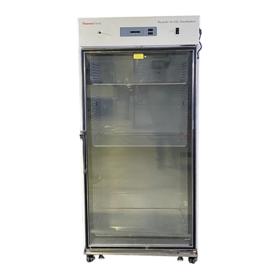
- Page 9 Forma Model 3950 Series ______________________________Installation and Start-up Section 1 - Installation and Start-Up POWER SWITCH TEMP/CO CONTROLS ¼” SAMPLE PORT HEATED GLASS DOOR DOOR LATCH (4) CASTERS (4) ADJUSTABLE LEVELING FOOT...
- Page 10 Forma Model 3950 Series ______________________________Installation and Start-up ACCESSORY OUTLET (2) 2.375 I.D. PORT WITH HOLE PLUG Figure 1-2 Side View RS 485 CONNECTION RJ-11 OPTIONAL REMOTE ALARM CONTACTS RJ-11 POWER INLET ¼” FILTERED CO CONNECTION CONNECTION Figure 1-3 Back View 1/4”...
-
Page 11: Control Panel Keys, Displays And Indicators
Forma Model 3950 Series ______________________________Installation and Start-up 1.2 Control Panel Keys, Displays and Indicators R un S et C al C onfi g H eat Tem p 36. 9 E n te r M o d e S i l e n ce... -
Page 12: Operation Of The Keypad
Forma Model 3950 Series ______________________________Installation and Start-up 1.3 Operation of the Keypad The Model 3950 Series Reach-In Incubator has four basic modes that allow incubator setup: Run, Setpoints, Calibration and System Configuration. Run is the default mode during normal operation. -
Page 13: Installing The Unit
Forma Model 3950 Series ______________________________Installation and Start-up Scroll for Parameters Arrows: Steps the operator through the parameters of SET, CAL and CONFIG Modes. The right arrow goes to the next parameter, the left arrow returns to the previous parameter. Up Arrow: Increases or toggles the parameter values that have been selected in the SET, CAL, and CONFIG Modes. -
Page 14: Installing The Shelves
Forma Model 3950 Series ______________________________Installation and Start-up Before using any cleaning or decontamination method except those recommended by the manufacturer, users should check with the manufacturer that the proposed method will not damage the equipment. Accidental spills of hazardous materials on or inside this unit are the responsibility of the user. -
Page 15: Attaching The Drain Lines
Forma Model 3950 Series ______________________________Installation and Start-up Top View e. Attaching the Drain Lines of Fitting Connections NOTE: Drain connections on the back of the unit are shipped capped. If humidity is not required, the caps should be left 3/8” fitting (not included) on the drains. -
Page 16: Filling The Humidity Reservoir
Forma Model 3950 Series ______________________________Installation and Start-up Distilled or de-ionized water used in the humidity reservoir must be within a water quality resistance range of 50K Ohm/cm to 1M Ohm/cm to protect and prolong the life of the stainless steel. Use of water outside the specified range will decrease the operating life of the unit and may void the warranty. -
Page 17: Gravity Fill Method
Plug the provided power cord into the power inlet connector on the back of the cabinet, then into the grounded, dedicated electrical circuit. The 3950 Series also has an internal outlet located on the right side of the interior back wall. This outlet is to provide power (230W maximum) to accessory equipment. -
Page 18: Connecting The Co Gas Supply
Forma Model 3950 Series ______________________________Installation and Start-up i. Connecting the CO Gas Supply High concentrations of CO gas can cause asphyxiation. OSHA Standards specify that employee exposure to carbon dioxide in any 8-hour shift of a 40-hour work week shall not exceed the 8-hour time weighted average of 5000 PPM (0.5% ). -
Page 19: Incubator Start-Up
Forma Model 3950 Series ______________________________Installation and Start-up The incubator has serrated fittings on the back of the cabinet to connect the gas supply. Refer to Figure 1-2. The fitting is labeled CO Inlet #1 Tank. Make sure that the connections are secured with clamps. -
Page 20: Setting The Co Setpoint
Forma Model 3950 Series ______________________________Installation and Start-up All Forma 3950 Series incubators are equipped with a secondary temperature monitoring system to monitor the air temperature inside the cabinet. This system is designed as a safety device to turn off all heaters in the event of a temperature control failure. The temperature control point in the incubator will be approximately + 1°C of the overtemp... - Page 21 Forma Model 3950 Series ______________________________Installation and Start-up Chart 1-1 Set Mode Press MODE to light SET Config Heat Temp 36.9 E nter M ode SET POINTS S ilence Inject % CO Scrol l for Parameters To Set: Nu mb ers increa se...
-
Page 22: Section 2 - Calibration
Forma Model 3950 Series _________________________________________Calibration Section 2 - Calibration 2.1 Calibration Mode After the unit has stabilized, several different systems can be calibrated. In the calibration mode, the air temperature, CO and RH levels can be calibrated to reference instruments. To access the calibration mode, press the Mode key until the Cal indicator lights. -
Page 23: Calibrating The Co
• Press the Mode key to return to Run or the right/left arrow to go to next/previous parameter. b. Calibrating the CO System Model 3950 Series incubators have a CO sensor. The incubator atmosphere is not only effected by the quantity of CO present but also by the air temperature and water vapor present in the incubator atmosphere. - Page 24 Forma Model 3950 Series _________________________________________Calibration...
-
Page 25: Section 3 - Configuration
Forma Model 3950 Series ___________________________________________Configuration Section 3 - Configuration 3.1 Configuration Mode Several features available in the Configuration Mode allow custom setup of the incubator. These features are listed and described below. All features may not be necessary in all applications, but are available if needed. -
Page 26: Setting A Low Temp Alarm Limit (Tracking Alarm)
Forma Model 3950 Series ___________________________________________Configuration d. Setting a Low Temp Alarm Limit (tracking alarm) The low temp alarm limit is the deviation from the temperature setpoint, which will cause a low temp alarm. The low temp alarm is variable from 0.5 degrees below setpoint to 5.0 degrees below setpoint. -
Page 27: Setting A High Co
Forma Model 3950 Series ___________________________________________Configuration g. Setting a High CO Alarm Limit (tracking alarm) The high CO alarm limit is the deviation from the CO setpoint, which will cause a high CO alarm. The setpoint is variable from 0.5 %CO above setpoint to 5.0 %CO... -
Page 28: Setting A New Span Number For New Co
Forma Model 3950 Series ___________________________________________Configuration i. Setting a New Span Number for CO Sensors If a new CO sensor is being installed, the two numbers on the factory installed sticker on the cell must be entered to calibrate the CO in the unit. -
Page 29: Enabling The Gas Guard System
Forma Model 3950 Series ___________________________________________Configuration m. Enabling the Gas Guard System On units equipped with the Gas Guard option, the Gas Guard system may be turned ON or OFF if it is not in use. The factory setting is OFF. - Page 30 Forma Model 3950 Series ___________________________________________Configuration Chart 3-1 Configure Mode Page 1 of 2 Press MODE to light CONFIG R u n Se t C a l C o nfig H e at Tem p 36.9 SYS CONF IG Enter Mode...
- Page 31 Forma Model 3950 Series ___________________________________________Configuration Configure Mode, Chart 3-1, Page 2 of 2 refer to previous page To Configure: Numbers increase CO % High Limit Press Enter to CO HI X.X % Enter Mode save the setting Scroll for Parameters...
- Page 32 Section 4 - Alarms 4.1 Alarms The Model 3950 Series incubator is equipped with a system which notifies the user of an alarm condition inside the incubator. All alarms are displayed in the control panel message center. The following table contains information on all possible systems alarms.
- Page 33 Forma Model 3950 Series ________________________________________________Alarms 4.2 Sensor Fault Alarms The microprocessor in 3950 Series incubators continually scans all available sensors to ensure that they are operating properly. Should an error be detected, the incubator will sound an alarm and display the appropriate message. If such an alarm occurs, contact your local distributor or the Forma Scientific service department at 740-373-4763 or 1-888-213-1790 (USA and Canada) or fax 740-373-4189.
-
Page 34: Sensors
PREVENTIVE MAINTENANCE Incubators Your Thermo Forma equipment has been thoroughly tested and calibrated before shipment. Regular preventive maintenance is important to keep your unit functioning properly. The operator should perform routine cleaning and maintenance on a regular basis. For maximum performance and efficiency, it is recommended the unit be checked and calibrated periodically by a qualified service technician. - Page 35 Incubators ______________________________________________________________________________ Preventive Maintenance Preventive Maintenance for 3950 Series Incubators Refer to Action Daily Weekly Yearly Manual Section 1.4ie Check CO tank levels. Check CO and temperature display versus setpoints Inspect door latch, hinges and door gasket seal. * Verify and document CO and temperature calibration 1.4b, 5.3...
-
Page 36: Section 5: Maintenance
Forma Model 3950 Series___________________________________________Maintenance Section 5: Maintenance If the unit has been in service, turn it off and disconnect the power cord connector before proceeding with any maintenance. Before using any cleaning or decontamination method except those recommended by the manufacturer, users should check with the manufacturer that the proposed method would not damage the equipment. -
Page 37: Cleaning The Glass Doors
Forma Model 3950 Series___________________________________________Maintenance 5.2 Cleaning the Glass Doors The chamber glass door and the optional independent inner doors may be cleaned using the same disinfectant as used on the incubator interior. It is imperative that they be rinsed with sterile distilled water to remove the disinfectant residue. -
Page 38: Replacing The Power Fuses
Forma Model 3950 Series___________________________________________Maintenance Distilled water used in the incubator humidifier reservoir must be within the 50K Ohm to 1M Ohm range to protect and prolong the life of the stainless steel unit. Use of tap water or distilled water outside the specified range will decrease the operating life of the unit and may void the warranty. - Page 39 Forma Model 3950 Series___________________________________________Maintenance Table 5-1, Fuse Replacement Chart Fuse Voltage and Manufacturers Part # Amp Rating Rupture Speed IEC Letter Application Code 115 VAC Accessory Outlet GMC-1A 1.0 Amp Time-Lag 230 VAC Accessory Outlet GMC-500mA 0.5 Amp Time-Lag 115 VAC Interior Outlet GMC-2.5A...
-
Page 40: Section 6 - Options (Factory Installed)
Forma Model 3950 Series _________________________________________Factory Options Section 6 - Factory Options 6.1 Connections to External Equipment a. Connecting the Remote Alarm Contacts A set of relay contacts is provided to monitor alarms through a RJ-11 telephone style connector on the back of the unit. Refer to Figure 6-3 for the location of the alarm connector. The 12-foot telephone cord (P/N 190388) and RJ11-to-screw terminal conversion box (190392) are available through Forma’s service department. -
Page 41: Connecting The Rs485 Interface
Forma Model 3950 Series _________________________________________Factory Options b. Connecting the RS485 Interface (190523) All incubator models can be purchased with the RS485 communications option. This option allows the incubator to be directly connected to a Forma Model 1535 alarm system without the use of a communications module. - Page 42 Forma Model 3950 Series _________________________________________Factory Options The analog output board is an option that allows the incubator to output analog signals representing the air temperature and CO content of the incubator interior. There are three different analog output board options available: 0-1V, 0-5V or 4-20mA signals. Refer to Table 6-1 for output specifications of the three boards.
-
Page 43: Co Gas Guard
Refer to the warnings in Section 1.4.i of this manual. The 3950 Series incubators can be equipped with a built-in Gas Guard system that will operate with a CO gas supply. The Gas Guard uses two pressure switches to continuously... -
Page 44: Connecting The Go 2 Gas Supplies
Forma Model 3950 Series _________________________________________Factory Options The CO gas supplies must be equipped with two-stage pressure regulators with gauges. The high pressure gauge at the tank should have a 0-2000 psig range and the low pressure gauge should have a 0-30 psig range. The gas supply to the incubator must be maintained at 15 psig (1.034 bar). -
Page 45: Inner Doors
Forma Model 3950 Series _________________________________________Factory Options Audible and visual alarms occur on the control panel when the gas guard switches from one supply to the other. The audible alarm sounds until the operator presses the Silence key on the control panel. The visual alarm in the... -
Page 46: Section 7 - Specifications
Forma Model 3950 Series _______________________________________Specifications Section 7 – Specifications 7.1 Specifications* * Specifications are based on nominal voltages of 115V or 230V in ambient temperatures of 22°C to 35°C Temperature Control: 0.1°C Microprocessor PID Setpoint: Digital – Touch Pad, 0.1°C Range: +5°C above ambient to 60°C... - Page 47 Forma Model 3950 Series _______________________________________Specifications Construction Interior volume: 29 cu ft (823 liters) Interior: 304 stainless steel, 2B finish Exterior: 18-gauge cold rolled steel Exterior Door: Heated, triple pane tempered glass Outer Door Gasket: Molded vinyl Insulation: 2” fiberglass Fittings Access Port: 2.4”...
- Page 48 RS-485 interface, FI (compatible with 1535 alarm monitor only) 190543 0-5 volt output board, FI 190544 0-1 volt output board, FI Certification: 3950 Series - UL, CSA, CE 3951 Series – CSA, CE Safety Specifications: Altitude: 2,000 meters Temperature: 5°C to 40°C Humidity: 80% RH at or below 31°C, decreasing linearly to 50% RH at 40°C...
- Page 49 Forma Model 3950 Series _______________________________________Specifications Installation category (overvoltage category) defines the level of transient overvoltage which the instrument is designed to withstand safely. It depends on the nature of the electricity supply and its overvoltage protection means. For example, in CAT II which is the category used for...
-
Page 50: Section 8 - Spare Parts
Forma Model 3950 Series _______________________________________Spare Parts Section 8 - Spare Parts Part Number Description 230135 1 amp fuse. (Model 3950 accessory outlet) 230158 2.5 amp fuse. (Model 3950 interior outlet) 230120 0.5 amp fuse. (Model 3951 accessory outlet) 230106 1.5 amp fuse. (Model 3951 interior outlet) 156112 Blower motor. -
Page 60: Section 9 - Electrical Schematics
Forma Model 3950 Series _______________________________Electrical Schematics Section 9 - Electrical Schematics... - Page 61 Forma Model 3950 Series _______________________________Electrical Schematics...
- Page 62 Forma Model 3950 Series _______________________________Electrical Schematics...
- Page 63 Forma Model 3950 Series _______________________________Electrical Schematics...
- Page 64 Forma Model 3950 Series _______________________________Electrical Schematics...
Need help?
Do you have a question about the 3950 and is the answer not in the manual?
Questions and answers