Table of Contents
Advertisement
Quick Links
Forma Scientific, Inc.
Millcreek Road, P.O. Box 649
Marietta, Ohio 45750
U.S.A.
Telephone: (740) 373-4763
Telefax: (740) 373-4189
______________________________________
Operating and Maintenance
Failure to read, understand and follow the instructions in this manual may result in damage to the
unit, injury to operating personnel and poor equipment performance.
CAUTION! All internal adjustments and
maintenance must be performed
by qualified service personnel.
*Refer to listing of models on Page iii.
Model: 310 Series*
Direct Heat
CO
2
Manual
Manual No: 7000310
Read this Instruction Manual
Incubator
Rev. 4
Refer to the serial tag on the
rear cover of this manual
Advertisement
Table of Contents

Subscribe to Our Youtube Channel
Related Manuals for Forma Scientific 310 Series


Summary of Contents for Forma Scientific 310 Series
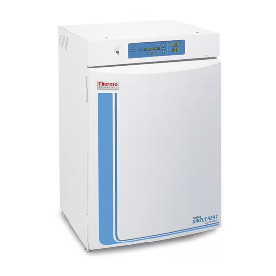
- Page 1 Forma Scientific, Inc. Millcreek Road, P.O. Box 649 Marietta, Ohio 45750 U.S.A. Telephone: (740) 373-4763 Telefax: (740) 373-4189 ______________________________________ Model: 310 Series* Direct Heat Incubator Operating and Maintenance Manual Manual No: 7000310 Rev. 4 Read this Instruction Manual Failure to read, understand and follow the instructions in this manual may result in damage to the unit, injury to operating personnel and poor equipment performance.
- Page 2 The material in this manual is for information purposes only. The contents and the product it describes are subject to change without notice. Forma Scientific, Inc. makes no representations or warranties with respect to this manual. In no event shall Forma Scientific, Inc.
- Page 3 Forma Model 310 Series _________________________________________________ Model Sensor* Voltage** *T/C is a thermal conductivity sensor. IR is an infrared sensor. **All units are 50/60 HZ If the incubator is not used in the manner specified in this operating manual, the protection provided by the equipment...
- Page 4 Forma Model 310 Series _________________________________________________ General Safety Notes used in this Manual Important operating and/or maintenance instructions. Read the accompanying text carefully. Ce symbole attire l’attention de l’utilisateur sur des instructions importantes de fonctionnement et/ou d’entretien. Il peut être utilisé seul ou avec d’autres symboles de sécurité.
- Page 5 Monday through Friday from 8:00 a.m. to 7:00 p.m. Eastern Time. Please contact us by telephone or fax. If you wish to write, our mailing address is: Forma Scientific, Inc. Millcreek Road, PO Box 649 Marietta, OH 45750 International customers, please contact your local Forma Scientific, Inc. distributor.
-
Page 6: Table Of Contents
Forma Model 310 Series _________________________________________________ Table of Contents Section 1 - Installation and Start-Up 1.1 Incubator Components ................1-1 1.2 Control Panel Keys, Displays and Indicators..........1-2 1.3 Operation of the Keypad ................1-3 1.4 Displays....................... 1-4 1.5 Installing the Unit..................1-4 a. - Page 7 Forma Model 310 Series ________________________________________Contents Section 3 - Configuration 3.1 Configuration Mode ..................3-1 a. Turning the Audible Alarm ON/OFF..........3-1 b. Setting an Access Code..............3-1 c. Setting a Low Temp Alarm Limit (tracking alarm) ......3-2 d. Enabling Temp Alarms to Trip Contacts .......... 3-2 e.
- Page 8 Forma Model 310 Series ________________________________________Contents Section 6 - Factory Installed Options 6.1 Connections to External Equipment ............6.1 a. Connecting the Remote Alarm Contacts........... 6.1 b. Connecting the RS485 Interface ............6-2 c. Connecting the Analog Outboards ............ 6-2 6.2 CO Gas Guard ...................
-
Page 9: Section 1 - Installation And Start-Up
Forma Model 310 Series _______________________________________ Installation Start-Up Section 1 - Installation and Start-up 1.1 Incubator Components C ont rol P anel C ham ber G as S am pl e P ort P ow er S ee S w i t ch... -
Page 10: Control Panel Keys, Displays And Indicators
Forma Model 310 Series _______________________________________ Installation Start-Up 1.2 Control Panel Keys, Displays and Indicators Figure 1-2 Control Panel R un S et C al C onfi g H eat Tem p 36. 9 E n te r M o d e... -
Page 11: Operation Of The Keypad
Forma Model 310 Series _______________________________________ Installation Start-Up 1.3 Operation of the Keypad The Model 310 Series direct heat incubator has four basic modes which allow incubator setup: Run, Setpoints, Calibration and System Configuration. Run is the default mode which the incubator will normally be in during operation. -
Page 12: Displays
Forma Model 310 Series _______________________________________ Installation Start-Up Scroll for Parameters Arrows: Steps the operator through the parameters of SET, CAL and CONFIG Modes. The right arrow goes to the next parameter, the left arrow returns to the previous parameter. Up Arrow: Increases or toggles the parameter value that has been selected in the SET, CAL, and CONFIG Modes. -
Page 13: Stacking The Incubators
Stacking the Incubators When stacking incubators, the direct heat incubator must be the top unit. Never stack a water-jacketed incubator on top of a 310 Series unit. With incubators in a stacked configuration, do not leave both exterior doors open at the same time. - Page 14 Forma Model 310 Series _______________________________________ Installation Start-Up This incubator weighs 205 lbs. Have sufficient personnel when lifting. Lift the unit only by the sides of the cabinet base. Do not attempt to lift it by the front and back as this places stress on the outer door hinge.
-
Page 15: Preliminary Cleaning And Disinfecting
Forma Model 310 Series _______________________________________ Installation Start-Up c. Preliminary Cleaning and Disinfecting 1. Remove the protective plastic coating on the shelf supports and air duct, if present. 2. Using a suitable laboratory disinfectant, disinfect all interior surfaces including shelves and shelf supports, door gaskets, blower wheel and CO sensor. -
Page 16: Installing Access Port Filter
Forma Model 310 Series _______________________________________ Installation Start-Up Figure 1-9 shows one of the channels installed on the right shelf support. Figure 1-9 e. Installing the Access Port Filter Locate the opening in the top left corner of the interior chamber. Install the smaller, beveled end of the stopper into the opening. -
Page 17: Leveling The Unit
Forma Model 310 Series _______________________________________ Installation Start-Up Bl ow er f an i nl et H EPA f i l t er Install in the access port from the inside of the incubator Access Port Filter Figure 1-11 HEPA Filter Figure 1-10 g. -
Page 18: Filling The Humidity Pan
Forma Model 310 Series _______________________________________ Installation Start-Up Optional Accessory CO Inlet Section RS 485 #1 Tank Outlet 1.5, 1.6 (75 watts max.) and 5 CO inject CO inject ACCESSORY 15 p.s.i. Regulated 15 p.s.i. Regulated 75 WATTS MAX . (103.4 kPa) (103.4 kPa) -
Page 19: Connecting The Co Gas Supply
Forma Model 310 Series _______________________________________ Installation Start-Up Distilled or de-ionized water used in the humidity pan must be within a water quality resistance range of 50K Ohm/cm to 1M Ohm/cm to protect and prolong the life of the stainless steel. Use of water outside the specified range will decrease the operating life of the unit and may void the warranty. -
Page 20: Incubator Start-Up
Setting the Operating Temperature All 310 Series incubators have an operating temperature range of 10°C to 50°C, depending on ambient temperature. The incubator is shipped from the factory with a temperature setpoint of 10°C. At this setting, all heaters and alarms are turned off. To change the operating temperature setpoint: 1. -
Page 21: Setting The Overtemp Setpoint
Forma 310 Series incubators are equipped with a secondary temperature monitoring system to monitor the air temperature inside the cabinet. This system is designed as a safety device to turn off all heaters in the event of a temperature control failure. - Page 22 Forma Model 310 Series _______________________________________ Installation Start-Up All models of the incubator have a CO setpoint range of 0.0% to 20.0%. The incubator is shipped from the factory with a CO setpoint of 0.0%. At this setting, all CO control and alarms are turned off.
- Page 23 Forma Model 310 Series _______________________________________ Installation Start-Up Set Mode P ress M O D E t o l i ght S E T R u n S e t C a l C o n fi g H e a t Te m p 36.
-
Page 24: Section 2 - Calibration
Forma Model 310 Series ______________________________________________Calibration Section 2 - Calibration 2.1 Calibration Mode After the unit has stabilized, several different systems can be calibrated. In the calibration mode, the air temperature, CO and RH levels can be calibrated to reference instruments. To access the calibration mode, press the Mode key until the Cal indicator lights. -
Page 25: Calibrating The Thermal Conductivity Co System
Forma Model 310 Series ______________________________________________Calibration b. Calibrating the Thermal Conductivity CO System Models 310, 311, 350 and 351 have a thermal conductivity (T/C) CO sensor. Thermal conductivity of the incubator atmosphere is not only effected by the quantity of CO present but also by the air temperature and water vapor present in the incubator atmosphere. -
Page 26: Ir Co 2 Sensor Stabilization Times
7. Press the Mode key to return to Run mode. d. Calibrating Relative Humidity All 310 Series incubators can be equipped with an optional direct read out relative humidity sensor. This is a readout only of the chamber relative humidity level. It does not provide any control of the relative humidity in the cabinet. - Page 27 Forma Model 310 Series ______________________________________________Calibration If a reliable RH measuring device is not available, you may calibrate the display to a typical level; 1. Follow the RH stabilization periods outlined above. 2. With a full humidity pan and stable temperature, the relative humidity in the chamber will be 95%.
- Page 28 Forma Model 310 Series ______________________________________________Calibration Chart 2-1 Calibrate Mode Press MODE to light CAL Config Temp 36.9 CALIBRATE Enter Mode Silence % CO Scroll for Parameters To Calibrate: Numbers increase Press MODE to move Operating to SYS CONFIG Enter Mode TEMPCAL XX.X...
-
Page 29: Section 3 - Configuration
Forma Model 310 Series_____________________________________________Configuration Section 3 - Configuration 3.1 Configuration Mode Several features available in the Configuration Mode allow custom setup of the incubator. These features are listed and described below. All features may not be necessary in all applications, but are available if needed. To enter Configuration mode, press the Mode key until the Config indicator lights. -
Page 30: Setting A Low Co Alarm Limit (Tracking Alarm)
Forma Model 310 Series_____________________________________________Configuration 1. Press the Mode key until the Config indicator lights. 2. Press the right arrow until Temp Lo -X.X is displayed in the message center. 3. Press up/down arrow to change the low temp alarm limit. 4. -
Page 31: Setting A High Co Alarm Limit (Tracking Alarm)
Forma Model 310 Series_____________________________________________Configuration f. Setting a High CO Alarm Limit (tracking alarm) The high CO alarm limit is the deviation from the CO setpoint which will cause a high CO alarm. The setpoint is variable from 0.5 %CO above setpoint to 5.0 %CO above setpoint. -
Page 32: Setting A New Span Number For T/C Co Sensors
Forma Model 310 Series_____________________________________________Configuration i. Setting a New Span Number for T/C CO Sensors If a new T/C CO sensor is being installed, the two numbers on the factory installed sticker on the T/C cell must be entered to calibrate the CO in the unit. -
Page 33: Enabling Temp/Rh To Be Displayed
Forma Model 310 Series_____________________________________________Configuration l. Enabling Temp/RH to be Displayed On units that are equipped with the RH option, the upper seven segment display on the control panel can be configured to display Temp continuously, RH continuously, or toggle between Temp and RH. - Page 34 Forma Model 310 Series_____________________________________________Configuration o. Setting a RS485 Communications Address (1535 compatible only) On units that have the RS485 option, direct communication with the Forma 1535 Model alarm system can be established. Each piece of equipment connected to the 1535 must have a unique address.
-
Page 35: Section 4 - Alarms
Section 4 - Alarms 4.1 Alarms The Model 310 Series incubator alarm system is shown in the table below. When an alarm is active, the message appears in the LED message center. Pressing Silence disables the audible alarm for the ringback period. However, the visual alarm continues until the incubator returns to a normal condition. -
Page 36: Temperature Controller Failure Tmp Cntr Err (Alarm)
4.2 Temperature Controller Failure TMP CNTR ERR (alarm) In addition to other safety features designed into Forma 310 Series incubators, a thermostat is also provided to monitor the cabinet’s temperature. In the unlikely event of a temperature control failure, the thermostat will turn off all heaters at a cabinet temperature of 65°C, +/-10%. - Page 37 Forma Model 310 Series _________________________________________________Alarms Possible problems which will cause this alarm are: • Auto Zero pump, orifice, filter or tubing will not let air to the sensor. Possibilities are: Defective or electrically disconnected air pump Kinked auto zero vinyl tubing...
-
Page 38: Section 5: Routine Maintenance
Forma Model 310 Series___________________________________________Maintenance Section 5: Routine Maintenance If the unit has been in service, turn it off and disconnect the power cord connector before proceeding with any maintenance. 5.1 Disinfecting the Incubator Interior Before using any cleaning or decontamination method except those recommended by the manufacturer, users must check with the manufacturer that the proposed method will not damage the equipment. -
Page 39: Cleaning The Cabinet Exterior
Forma Model 310 Series___________________________________________Maintenance 1. Remove the shelves, HEPA filter (a factory installed option), access port filter, sample air filter, left and right duct sheets and the top duct. The top duct requires the two wing nuts to be removed. 2. -
Page 40: Cleaning The Humidity Pan
Forma Model 310 Series___________________________________________Maintenance Some precautions in the cleaning and care of the incubator glass doors: Moisture leaches alkaline materials (sodium, Na) from the surface of the glass. Evaporation of the moisture concentrates the alkaline and may produce a white staining or clouding of the glass surface. - Page 41 Forma Model 310 Series___________________________________________Maintenance 1. Remove the kick plate at the bottom of the cabinet by removing Figure 5-1 the two Phillips screws indicated by the black arrows in the illustration. Disconnect the cable inside the cabinet. 2. Open the outer door and remove it by lifting it off its hinge pins.
- Page 42 Forma Model 310 Series___________________________________________Maintenance Figure 5-4 8. Remove the nylon screws along the right side of the cabinet. Remove the outer door hinges (Items 1 in Figure 5-5). Rotate them 180° and install them on the right side of the cabinet (Locations 2).
- Page 43 Forma Model 310 Series___________________________________________Maintenance 15. Using a flat blade screwdriver, remove the threaded nylon plugs from the new hinge bracket locations (Locations 8 and 9). Install the lower hinge bracket,(Item 5 removed earlier) at Location 8. 16. Rotate the door 180° and place it in the lower hinge bracket.
-
Page 44: The Electronics Section
Forma Model 310 Series___________________________________________Maintenance 5.7 Replacing the Power Fuses There are only two replaceable fuses in the incubator. To access the fuses: 1. Turn off the incubator’s power switch and unplug the power cord. 2. Open the outer door to the chamber. 3. - Page 45 Forma Model 310 Series___________________________________________Maintenance a. The major components Refer to Figure 5-8. Some of the components shown in this illustration are factory installed options. They are identified as such in the descriptions below. Power Switch - Located beneath the control panel. The outer door 10.
- Page 46 Forma Model 310 Series___________________________________________Maintenance Figure 5-8...
-
Page 47: Replacing The Sample Air Filter
Forma Model 310 Series___________________________________________Maintenance 5.9 Replacing Sample Air Filter (Figure 5-9) B l ow er f an i nl et 1. Connect one end of the sample port filter to the ceiling port. 2. Connect the other end of the filter to the back of the blower fan inlet. -
Page 48: Section 6 - Factory Installed Options
Forma Model 310 Series __________________________________________Factory Options Section 6 - Factory Options 6.1 Connections to External Equipment a. Connecting the Remote Alarm Contacts A set of relay contacts is provided to monitor alarms through an RJ11 telephone style connector on the back of the cabinet. Refer to Figure 6-3 for the location of the alarm connector. -
Page 49: Connecting The Rs485 Interface
Forma Model 310 Series __________________________________________Factory Options b. Connecting the RS485 Interface (190523) All incubator models can be purchased with the RS485 communications option. This option allows the incubator to be directly connected to a Forma Model 1535 alarm system without the use of a communications module. - Page 50 Forma Model 310 Series __________________________________________Factory Options Table 6-1 Analog Output Board Specifications 190512 4-20 mA 190544 0-1V 190543 0-5V Output Scaling Output Scaling Output Scaling 4-20 mA Equals 0-1 V Equals 0-5V Equals Temperature 0.0-100.0 °C 0.0-100.0 °C 0.0-100.0 °C...
-
Page 51: Co Gas Guard
Refer to warnings in Section 1.5.j of this manual. The 310 Series incubators can be equipped with a built-in Gas Guard system that will operate with a CO gas supply. The Gas Guard uses two pressure switches to continuously... -
Page 52: Connecting The Go Gas Supplies
Forma Model 310 Series __________________________________________Factory Options The CO gas supplies must be equipped with two-stage pressure regulators with gauges. The high pressure gauge at the tank should have a 0-2000 psig range and the low pressure gauge should have a 0-30 psig range. The gas supply to the incubator must be maintained at 15 psig (1.034 bar). -
Page 53: Humidity Readout
Guard continues to detect that both gas supply pressures are below 10 psig (0.690 bars). 6.3 Humidity Readout (190643) The 310 Series incubators can be equipped with a humidity sensor to monitor the relative humidity inside the chamber. The sensor is mounted to the top air duct and provides a signal that is displayed in 1% increments on the control panel. -
Page 54: Accuracy Of The Humidity Readout
Forma Model 310 Series __________________________________________Factory Options b. Accuracy of the Humidity Readout: The sensor is capable of measuring relative humidity from 10% to 100% with an accuracy of ±5% above 90%. See Section 2, Calibration, for details on calibrating the humidity readout. - Page 55 Forma Model 310 Series __________________________________________Factory Options a. Connecting Uninterruptable Power Supply (P/N 270078, 115V, 50/60 Hz) Plug the incubator line cord into one of the receptacles on the back of the UPS. Then plug the UPS line cord into a suitable wall outlet.
- Page 56 Forma Model 310 Series ______________________________________Specifications Section 7 - Specifications* *Specifications are based on nominal voltages of 115V or 230V in ambients of 22°C to 25°C. Forma Models 310, 311, 320 and 321 Temperature Control ±0.1°C Microprocessor PID Control Setpoint Digital - Touch pad, 0.1°C Range +5°C above ambient to 50°C...
- Page 57 Forma Model 310 Series ______________________________________Specifications Shelves Dimensions 18.5” x 18.5” Construction Stainless Steel (belt sanded, both sides) Surface area 2.4 sq. ft. Max. per chamber 40.8 sq. ft. Standard Maximum Construction Interior volume 6.5 cu. ft. Interior Type 304 stainless steel shiny finish...
- Page 58 Forma Model 310 Series ______________________________________Specifications Options/Accessories HEPA filter Factory installed: Stock no. 190858 Battery back-up Free Standing: Stock no. 270078, 120VAC, 60Hz Stock no. 270082, 220VAC, 50Hz Humidity Factory installed: Stock no. 190463 - provides humidity readout and low alarm Inner door kit Customer installed: Stock no.
- Page 59 Forma Model 310 Series ______________________________________Specifications Safety Specifications Indoor Use Only Altitude - 2,000 meters Temperature - 5°C to 40°C Humidity - 80% RH at or below 31°C, decreasing linearly to 50% RH at 40°C Mains Supply Fluctuations - Mains supply voltage fluctuations not to exceed ±10% of the nominal voltage...
- Page 60 Forma Model 310 Series ____________________________________________ Parts Section 8 - Spare Parts Part Number Description 190699 Removable feather gasket 190670 Duct sheet and shelf channel kit 190772 Micro board, (main control) 230135 Fuse, 1A, TD, 5 x 20mm 230120 0.5A fuse, TD, 5 x 20mm (accessory outlet)
- Page 61 Forma Model 310 Series ____________________________________________ Parts Part Number Description 230153 6A, DPDT circuit breaker switch (power) 400199 Switcher, 40W, 12, 5, -12V 420096 130VA transformer, int’l, 12/24V S 194021 34 position control to display ribbon cable 420097 43VA transformer (230VAC units only)
- Page 62 Model 310 Series _____________________________________________________________________________Spare Parts...
- Page 63 Model 310 Series _____________________________________________________________________________Spare Parts...
- Page 64 Model 310 Series _____________________________________________________________________________Spare Parts...
- Page 67 Model 310 Series ______________________________________________________________________Electrical Schematics Section 9 - Electrical Schematics 9 -1...
- Page 68 Model 310 Series ______________________________________________________________________Electrical Schematics 9 -2...
- Page 69 Model 310 Series ______________________________________________________________________Electrical Schematics 9 -3...
- Page 70 Model 310 Series ______________________________________________________________________Electrical Schematics 9 -4...
- Page 71 Model 310 Series ______________________________________________________________________Electrical Schematics 9 -5...
- Page 72 Model 310 Series ______________________________________________________________________Electrical Schematics 9 -6...
Need help?
Do you have a question about the 310 Series and is the answer not in the manual?
Questions and answers