Forma Scientific 3920 Operating And Maintenance Manual
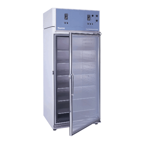
29 cu. ft. capacity reach-in incubator
Hide thumbs
Also See for 3920:
- Operating and maintenance manual (19 pages) ,
- Instruction manual (47 pages) ,
- Operating and maintenance manual (13 pages)

Related Manuals for Forma Scientific 3920


Summary of Contents for Forma Scientific 3920
- Page 1 Forma Scientific, Inc. Model 3920 29 cu. ft. Capacity Reach-In Incubator Operating and Maintenance Manual Manual No: 7033920 Rev. 7...
- Page 2 Forma Scientific, Inc. makes no repre- sentations or warranties with respect to this manual. In no event shall Forma Scientific, Inc. be held liable for any damages, direct or incidental, arising out of or related to the use of this manual.
- Page 3 Forma® Model 3920 _________________________________________________________________________________ Important operating and/or maintenance instructions. Read the accompanying text carefully. Ce symbole attire l'attention de l'utilisateur sur des instructions importantes de fonctionnement et/ou d'entretien. Il peut être utilisé seul ou avec d'autres symboles de sécurité. Lire attentivement le texte d'accompagnement.
- Page 4 Forma® Model 3920 _________________________________________________________________________________ Do You Need Information or Assistance on Forma Scientific Products? do, please contact us 8:00 a.m. to 7:00 p.m. (Eastern Time) at: If you 1-740-373-4763 Direct 1-888-213-1790 Toll Free, U.S. and Canada 1-740-373-4189 http://www.forma.com Internet Worldwide Web Home Page fservice@forma.com...
-
Page 5: Table Of Contents
Section 3 - Control Panel Operation ....3 - 1 3.1 The 3920 Control Panel ..... .3 - 1 3.2 Setting the Operating Temperature (Figure 3-3) . -
Page 6: Section 1 - Receiving
1.3 Responsibility for Shipping Damage the tubing, if desired. For products shipped F.O.B. Marietta, Ohio, the responsi- bility of Forma Scientific, Inc. ends when the merchandise is loaded onto the carrier’s vehicle. On F.O.B. Destination shipments, Forma Scientific and the carrier’s responsibility ends when your Receiving Department... -
Page 7: Rs-232 Output Interface & Remote Alarm Connector
2.5 Start-Up Procedure Connector Preset the controls as follows: The Model 3920 is equipped with an RS-232 Serial Overtemp Safety Thermostat ...(Fully Clockwise) Communication Interface for the remote transmission of tem- Undertemp Safety Thermostat . -
Page 8: Setting The Undertemp Safety Thermostat
Forma® Model 3920__________________________________________________________________Installation and Start-Up If the battery is weak or not connected, the green LED will 2.7 Setting the Undertemp Safety Thermostat flash. If power is lost to the cabinet, the LED will also flash. When replacing the 9-volt battery, use only an alkaline style Allow the chamber temperature to stabilize, then set the battery. -
Page 9: Offset Calibration
Forma® Model 3920__________________________________________________________________Installation and Start-Up 8. Turn on the main power switch. Note: For 2 pen operations, first select the pen you wish to cali- 9. Press the Up and Down Arrow keys simultaneously for brate. Hold down the #1 arrow for the red (#1) pen or the #2 3 seconds. - Page 10 (WATLOW 982) CONFIGURATION RECORD CUSTOMER: JOB NUMBER: UNT SERIAL NUMBER: CONTROL TYPE: Temperature PREPARED BY: DATE COMPLETED BY: DATE Switch Configuration: Main Boards Input 1 Board Output 3 Option board Jumper switch setting: Form B Software Configuration: Operations Menus SYS: Ei1S Ent4 A3LO -73.3...
- Page 11 HONEYWELL TRULINE CONFIGURATION RECORD SHT 1 OF 4 CUSTOMER: JOB NUMBER: UNIT SERIAL #: CONTROL TYPE: PREPARED BY: DATE: COMPLETED BY: DATE: GROUP FUNCTION VALUE OR GROUP FUNCTION VALUE OR PROMPT PROMPT SELECTION PROMPT PROMPT SELECTION TUNING1 PROP BD or CHART CHRTSPD 7 DAY...
- Page 12 HONEYWELL TRULINE CONFIGURATION RECORD SHT 2 OF 4 GROUP FUNCTION VALUE OR GROUP FUNCTION VALUE OR PROMPT PROMPT SELECTION PROMPT PROMPT SELECTION PEN4 PEN4 DISABLE INPUT4 DECIMAL PEN4IN UNITS CHART4HI ENGUNITS CHART4LO IN4TYPE PEN4ON XMITTER PEN4OFF IN4HI MAJORDIV IN4LO MINORDIV CUTOFF4 RNG4TAG INPTCOMP...
- Page 13 HONEYWELL TRULINE CONFIGURATION RECORD SHT 3 OF 4 GROUP FUNCTION VALUE OR GROUP FUNCTION VALUE OR PROMPT PROMPT SELECTION PROMPT PROMPT SELECTION CONTROL2 PID SETS ALARMS A1S1 VAL SW VALUE A1S2 VAL SP SOURC A1S1 TYPE NONE RATIO A1S2 TYPE NONE BIAS A1S1 HL...
- Page 14 HONEYWELL TRULINE CONFIGURATION RECORD SHT 4 OF 4 GROUP FUNCTION VALUE OR GROUP FUNCTION VALUE OR PROMPT PROMPT SELECTION PROMPT PROMPT SELECTION EVNT MSG EVENT 1 NONE MESSAGE 1 POSITION 1 EVENT 2 NONE MESSAGE 2 POSITION 2 EVENT 3 NONE MESSAGE 3 POSITION 3...
-
Page 15: Section 3 - Control Panel Operation
Forma® Model 3920 __________________________________________________________________Control Panel Operation Section 3 - Control Panel Operation The defrost switch must be turned on when the temperature setpoint is 10°C, or below. Overtemp Safety Control, Indicator Light, and Audible Alarm (Figure 3-2) The overtemp safety thermostat should be set slightly above the operating temperature of the incubator. -
Page 16: Setting The Operating Temperature (Figure 3-3)
Forma® Model 3920 __________________________________________________________________Control Panel Operation 3.2 Setting the Incubator’s Operating Temperature Looking at the top of (Figure 3-3) the module, locate the red DIP switch indicated in Figure 3-5. With a finger- DIP switch The Watlow temperature nail or small screwdriver, turn off SW #2 by moving controller’s upper numerical... - Page 17 PREVENTIVE MAINTENANCE Incubators Your Thermo Forma equipment has been thoroughly tested and calibrated before shipment. Regular preventive maintenance is important to keep your unit functioning properly. The operator should perform routine cleaning and maintenance on a regular basis. For maximum performance and efficiency, it is recommended the unit be checked and calibrated periodically by a qualified service technician.
- Page 18 Incubators ______________________________________________________________________________ Preventive Maintenance Preventive Maintenance for 3911/3920/3940/3980 Series Incubators Refer to Action Daily Weekly Yearly Manual Section Inspect door latch, hinges and door gasket seal. 3.5 (3911), 3.4 (3920), Check the air exchange ventilator caps for adjustment; open or closed as required 3.5 (3940), 3.17 (3980)
-
Page 19: Air Exchange Ventilator Caps
Forma® Model 3920 ___________________________________________________________________Routine Maintenance Press the down arrow key until the Section 4 - Routine Maintenance Change 2 becomes 0 (zero) as shown in Figure 2 to 0 3-9. Press the Display key to return to 4.1 Cleaning the Incubator showing the setpoint and actual tem- peratures. -
Page 20: Section 5 - Service
Forma® Model 3920 _______________________________________________________________________________Service 5.3 Replacing the Temperature Sensor Section 5 - Service 1. Locate the probe mounting plate in the center of the right side of the incubator interior. Servicing must be performed by qualified service 2. Open the mounting plate by removing the screws that personnel only! hold it in place. -
Page 21: Setting The Door Heater Control
Forma® Model 3920 _______________________________________________________________________________Service 8. Remove the nine 5/16” x 4” hex head bolts, lock wash- 5.5 Setting the Door Heater Control ers, and two flat washers which secure the top assembly to the cabinet. Note the washer arrangement on the bolts. -
Page 22: Section 6 - Specifications
Forma® Model 3920 _________________________________________________________________________Specifications Section 6 – Specifications Temperature Fittings Control ±0.3°C @ +25°C to +37°C Drain Port 3/8” OD Copper Range 0°C (32°F) to +60°C (140°F) Unit Heat Load Sensor 115V 5500 BTUH (1600W) Controller Digital electronic proportional 220V... -
Page 23: Section 7 - Parts List
Forma® Model 3920 ___________________________________________________________________________Parts List Section 7 - Parts List Part No. Description 290163 Sensor, RH/Temp Control 230066* Fuse, Ceramic 10A 350V 290162 RH/Temp Control Signal Conditioner 400051 Power Supply 231186 Controller, Watlow 982 Auto Tune 320277 Triac, 25A 403940 Thermostat, B-10 0-220°F (coated) - Page 25 Forma® Model 3920 ____________________________________________________________________Electrical Schematics 8 - 2...
- Page 26 Forma® Model 3920 ____________________________________________________________________Electrical Schematics 8 - 3...
- Page 27 Forma® Model 3920 ____________________________________________________________________Electrical Schematics 8 - 4...
- Page 28 Forma Scientific, Inc. Millcreek Road, P.O. Box 649 Marietta, Ohio 45750 U.S.A. Telephone (740) 374-4763 Telefax (740) 374 4189...
Need help?
Do you have a question about the 3920 and is the answer not in the manual?
Questions and answers