Forma Scientific 3940 Manual
Hide thumbs
Also See for 3940:
- Instruction manual (95 pages) ,
- Manual (56 pages) ,
- Operating and maintenance manual (31 pages)
Table of Contents
Advertisement
Quick Links
Forma Scientific, Inc.
Millcreek Road, P.O. Box 649
Marietta, Ohio 45750
U.S.A.
Telephone: (740) 373-4763
Telefax: (740) 373-4189
_____________________________________
Models:
3940 and 3949
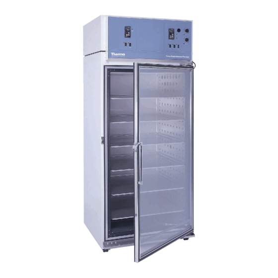
Reach-In Incubator
29 cu ft capacity
Manual No. 7033940
Rev. 7
Read this Instruction Manual
Failure to read, understand and follow the instructions in this manual may result in
damage to the unit, injury to operating personnel and poor equipment performance.
CAUTION: All internal adjustments and maintenance must be performed
by qualified service personnel.
Refer to the serial tag on the
rear cover of this manual
Advertisement
Table of Contents

Related Manuals for Forma Scientific 3940


Summary of Contents for Forma Scientific 3940
- Page 1 Marietta, Ohio 45750 U.S.A. Telephone: (740) 373-4763 Telefax: (740) 373-4189 _____________________________________ Models: 3940 and 3949 Reach-In Incubator 29 cu ft capacity Manual No. 7033940 Rev. 7 Read this Instruction Manual Failure to read, understand and follow the instructions in this manual may result in damage to the unit, injury to operating personnel and poor equipment performance.
- Page 2 Forma® Model 3940/3949 _______________________________________________________ The material in this manual is for information purposes only. The contents and the product it describes are subject to change without notice. Forma Scientific, Inc. makes no representations or warranties with respect to this manual. In no event shall Forma Scientific, Inc.
- Page 3 Monday through Friday from 8:00 a.m. to 7:00 p.m. Eastern Time. Please contact us by telephone or fax. If you wish to write, our mailing address is: Forma Scientific, Inc. Millcreek Road, PO Box 649 Marietta, OH 45750 International customers, please contact your local Forma Scientific distributor.
- Page 4 Forma® Model 3940/3949 ________________________________________________Safety General Safety Notes used in this Manual Important operating and/or maintenance instructions. Read the accompanying text carefully. Ce symbole attire l’attention de l’utilisateur sur des instructions importantes de fonctionnement et/ou d’entretien. Il peut être utilisé seul ou avec d’autres symboles de sécurité.
-
Page 5: Table Of Contents
Forma® Model 3940/3949 ________________________________________________Contents Table of Contents Section 1 - Receiving 1.1 Preliminary Inspection ..................1-1 1.2 Visible Loss or Damage................1-1 1.3 Responsibility for Shipping Damage ............1-1 Section 2 - Installation and Set-Up 2.1 Location ......................2-1 2.2 Water (Humidity System) and Drain Connections ........2-2 a. - Page 6 Forma® Model 3940/3949 ________________________________________________Contents Section 3 - Start Up and Operation 3.1 The Control Panel ..................3-1 a. Main Power Switch and Indicator Light.......... 3-1 b. Refrigeration Switch and Indicator Light..........3-1 c. Defrost Switch and Indicator Light............3-2 d. Overtemp Safety Control, Indicator Light, and Audible Alarm ..3-2 e.
- Page 7 Forma® Model 3940/3949 ________________________________________________Contents Section 6 - Specifications Section 7 - Spare Parts Section 8 - Refrigeration Schematic Section 9 - Electrical Schematics Section 10 - Warranty and Supplements...
-
Page 8: Section 1 - Receiving
Inc. ends when the merchandise is loaded onto the carrier's vehicle. On F.O.B. Destination shipments, Forma Scientific and the carrier's responsibility ends when your Receiving Department personnel sign a free and clear delivery receipt. Whenever possible, Forma Scientific will assist in settling claims for loss or in- transit damage. -
Page 9: Section 2 - Installation And Set-Up
Forma® Model 3940/3949 ________________________________________Installation/Set-Up Section 2 - Installation and Set-Up 13.250“ 87.50“ O.D. 60.0“ work space 72.750“ Horizontal air flow 31.0“ work space 1.50“ duct 1.50“ duct 27.0“ work space 1.0“ min. 2.0“ 34.0“ 2.0“ 2.0“ 29.0“ 31.0“ 38.0“ S i de F ront 3940-00 rev. -
Page 10: Water (Humidity System) And Drain Connections
Forma® Model 3940/3949 ________________________________________Installation/Set-Up 2.2 Water (Humidity System) and Drain Connections a. Connecting the Water Inlet for the Humidity System Do not attempt to operate the humidity system without filling it with water. The humidification heater will overheat, and the overtemp safety thermostat will shut the humidification system down. -
Page 11: Alternate Water Supply For The Humidity System
Forma® Model 3940/3949 ________________________________________Installation/Set-Up b. Alternate Water Supply for the Humidity System If an in-house water supply of the required purity range (50K to 1M Ohm) is not available, an alternate water supply method can be used. A large vented carboy (5 gal. -
Page 12: Remote Data Output
Forma® Model 3940/3949 ________________________________________Installation/Set-Up 2.3 Remote Data Output a. RS-232 Data Output The Model 3940/3949 incubator is equipped with an RS-232 Serial Communication Interface for the remote transmission of temperature and humidity data. A terminal strip is located on the back of the incubator for convenience. -
Page 13: Start-Up
Forma® Model 3940/3949 ________________________________________Installation/Set-Up 2.5 Start-Up When the humidification system is operational, the incubator may be started. Preset the controls as follows: Overtemp Safety Thermostat......Fully Clockwise Undertemp Safety Thermostat......Fully Counterclockwise Main Power Switch........ON Humidity Controller........Desired Setpoint Temperature Controller... -
Page 14: Setting The Undertemp Safety Thermostat
Forma® Model 3940/3949 ________________________________________Installation/Set-Up 2.7 Setting the Undertemp Safety Thermostat Allow the chamber temperature and humidity to stabilize, then set the undertemp safety thermostat as follows: 1. Turn the undertemp control knob slowly clockwise until the audible alarm sounds and the undertemp indicator lights. -
Page 15: Changing The Chart Paper
Forma® Model 3940/3949 ________________________________________Installation/Set-Up b. Changing the Chart Paper 1. Press the Change Chart button (#3) and hold it for 1 second until the pen begins to move to the left of the chart. See Figure 2-3. 2. Remove the existing chart by unscrewing the center knob securing it. -
Page 16: Offset Calibration
Forma® Model 3940/3949 ________________________________________Installation/Set-Up 2.9 Offset Calibration It may be necessary to calibrate the temperature or humidity controllers to match an independent temperature or humidity sensor. To do so, follow the next few steps. 1. Suspend an independent, calibrated sensor(s) in the center of the interior chamber. - Page 17 Forma® Model 3940/3949 ________________________________________Installation/Set-Up 11. Press the Mode key once, then the Up Arrow once. “InPt” will appear in the upper display, and “set” will be in the lower display. Press the Mode key until “CAL 1” appears in the lower display.
-
Page 18: Honeywell Recorder (Optional)
Copies of the Watlow Configuration records are included on the following pages. The controller should not be re-configured without first consulting Forma Scientific Service Department at 1-888- 213-1790. Refer to Section 3 of this manual for operating instructions for the Watlow controllers. - Page 19 Forma® Model 3940/3949 ________________________________________Installation/Set-Up Temperature Configuration 2-11...
- Page 20 3940 (WATLOW 982) CONFIGURATION RECORD CUSTOMER: JOB NUMBER: UNT SERIAL NUMBER: CONTROL TYPE: Temperature PREPARED BY: DATE COMPLETED BY: DATE Switch Configuration: Main Boards Input 1 Board Output 3 Option board Jumper switch setting: Form B Software Configuration: Operations Menus...
- Page 21 Forma® Model 3940/3949 ________________________________________Installation/Set-Up Humidity Configuration 2-12...
- Page 22 3940 (WATLOW 982) CONFIGURATION RECORD CUSTOMER: JOB NUMBER: UNT SERIAL NUMBER: CONTROL TYPE: Humidity PERPARED BY: DATE: COMPLETED BY: DATE: Switch Configuration: Main Boards Input 1 Board Output 3 Option board Jumper switch setting: Form B Software Configuration: Operations Menus...
- Page 23 Forma® Model 3940/3949 ________________________________________Installation/Set-Up Honeywell Trueline Recorder Configuration (Optional) 2-13...
- Page 24 HONEYWELL TRULINE CONFIGURATION RECORD SHT 1 OF 4 CUSTOMER: JOB NUMBER: UNIT SERIAL #: CONTROL TYPE: PREPARED BY: DATE: COMPLETED BY: DATE: GROUP FUNCTION VALUE OR GROUP FUNCTION VALUE OR PROMPT PROMPT SELECTION PROMPT PROMPT SELECTION TUNING1 PROP BD or CHART CHRTSPD 7 DAY...
- Page 25 HONEYWELL TRULINE CONFIGURATION RECORD SHT 2 OF 4 GROUP FUNCTION VALUE OR GROUP FUNCTION VALUE OR PROMPT PROMPT SELECTION PROMPT PROMPT SELECTION PEN4 PEN4 DISABLE INPUT4 DECIMAL PEN4IN UNITS CHART4HI ENGUNITS CHART4LO IN4TYPE PEN4ON XMITTER PEN4OFF IN4HI MAJORDIV IN4LO MINORDIV CUTOFF4 RNG4TAG INPTCOMP...
- Page 26 HONEYWELL TRULINE CONFIGURATION RECORD SHT 3 OF 4 GROUP FUNCTION VALUE OR GROUP FUNCTION VALUE OR PROMPT PROMPT SELECTION PROMPT PROMPT SELECTION CONTROL2 PID SETS ALARMS A1S1 VAL SW VALUE A1S2 VAL SP SOURC A1S1 TYPE NONE RATIO A1S2 TYPE NONE BIAS A1S1 HL...
- Page 27 HONEYWELL TRULINE CONFIGURATION RECORD SHT 4 OF 4 GROUP FUNCTION VALUE OR GROUP FUNCTION VALUE OR PROMPT PROMPT SELECTION PROMPT PROMPT SELECTION EVNT MSG EVENT 1 NONE MESSAGE 1 POSITION 1 EVENT 2 NONE MESSAGE 2 POSITION 2 EVENT 3 NONE MESSAGE 3 POSITION 3...
-
Page 28: Section 3 - Start Up And Operation
Forma® Model 3940/3949 ________________________________________Start-Up/Operation Section 3 - Start Up and Operation Figure 3-1, Reach-In Incubator Control Panel shown with optional CoBex Recorder 3.1 The Control Panel Main Power Switch and Indicator Light (Figure 3-2) The main power switch controls power to the incubator. -
Page 29: Defrost Switch And Indicator Light
Forma® Model 3940/3949 ________________________________________Start-Up/Operation Defrost Switch and Indicator Light (Figure 3-2) The defrost switch controls power to the defrost system. The defrost timer is factory set to provide two 15-minute defrost cycles during a twenty-four hour period. The defrost indicator lights when the defrost switch is on and the incubator is in a defrost cycle. -
Page 30: Dehumidify Switch And Indicator Light
Forma® Model 3940/3949 ________________________________________Start-Up/Operation Note: As with the overtemp safety control, the undertemp control is not directly calibrated. The numbers (0 to 10) on the dial are for reference only and do not correspond to any specific temperature. If an undertemp condition occurs, the alarm can only be silenced by lowering the undertemp safety thermostat setting. -
Page 31: Setting The Incubator's Operating Temperature
Forma® Model 3940/3949 ________________________________________Start-Up/Operation Pressing the Hold/Run key (Figure 3-4, Item J) on the controller silences the audible alarm and extinguishes the humidity alarm indicator. The L3 indicator on the controller, however, remains lit until the cabinet humidity returns to the system setpoint. -
Page 32: Setting The Incubator's Operating Humidity
Making program changes to either the temperature or humidity controllers will seriously alter the performance of the incubator and therefore must be made only by qualified persons. The controllers should not be re-configured without first consulting Forma Scientific, Service Department, at 1-888-213-1790. -
Page 33: Removing The Mechanical Lockout
Forma® Model 3940/3949 ________________________________________Start-Up/Operation a. Removing the mechanical lockout Make sure the unit is turned off. Wearing a grounding wrist strap or main- Front Vi ew taining constant contact with the metal cabinet, press in the four locking tabs on the frame of the Temperature controller. - Page 34 Forma® Model 3940/3949 ________________________________________Start-Up/Operation Global Input Press Press (3 sec) Figure 3-10 Figure 3-9 Press the Mode key to scroll through the menus until the upper and lower displays show “2 Loc” (Figure 3-11). Press the down arrow key until the 2 becomes 0 (zero) as shown in Figure 3-12.
-
Page 35: Air Exchange Ventilator Caps
Reprogramming the temperature or humidity controllers will change the factory default settings and may seriously alter the performance of the incubator and void the warranty. Contact the Forma Scientific, Service Department, at 1-888-213-1790. 3.5 Air Exchange Ventilator Caps Air exchange for the incubator is regulated through the manually adjustable intake and exhaust ventilator caps located on the top of the cabinet. - Page 36 PREVENTIVE MAINTENANCE Incubators Your Thermo Forma equipment has been thoroughly tested and calibrated before shipment. Regular preventive maintenance is important to keep your unit functioning properly. The operator should perform routine cleaning and maintenance on a regular basis. For maximum performance and efficiency, it is recommended the unit be checked and calibrated periodically by a qualified service technician.
- Page 37 Incubators ______________________________________________________________________________ Preventive Maintenance Preventive Maintenance for 3911/3920/3940/3980 Series Incubators Refer to Action Daily Weekly Yearly Manual Section Inspect door latch, hinges and door gasket seal. 3.5 (3911), 3.4 (3920), Check the air exchange ventilator caps for adjustment; open or closed as required 3.5 (3940), 3.17 (3980)
-
Page 38: Section 4 - Routine Maintenance
Forma® Model 3940/3949 ___________________________________________Maintenance Section 4 - Routine Maintenance 4.1 Cleaning the Incubator De-energize all potential sources of energy to this unit and lockout/tagout their controls. (O.S.H.A. Regulation, Section 1910-147.) The continued cleanliness of the stainless steel used in Forma products has a direct effect on the appearance and operation of the unit. -
Page 39: Section 5 - Service
Forma® Model 3940/3949 _________________________________________________Service Section 5 - Service Contains Parts and Assemblies Susceptible to Damage by Electrostatic Discharge (ESD) Servicing must be performed by qualified service personnel only! 5.1 Accessing the Electrical Components De-energize all potential sources of energy to this unit and lockout/tagout their controls. -
Page 40: Replacing The Overtemp/Undertemp Probe And Thermostat
Forma® Model 3940/3949 _________________________________________________Service 5.2 Replacing the Overtemp/Undertemp Probe and Thermostat De-energize all potential sources of energy to this unit and lockout/tagout their controls. 1. Remove the incubator ceiling by remove the screws holding it in place. 2. Remove the top three screws from the top of the right duct cover. -
Page 41: Replacing The Humidity/Temperature Sensor
Forma® Model 3940/3949 _________________________________________________Service 5.3 Replacing the Humidity/Temperature Sensor De-energize all potential sources of energy to this unit and lockout/tagout their controls. 1. Locate the probe mounting plate in the center of the right side of the incubator interior. 2. Open the mounting plate by removing the screws that hold it in place. -
Page 42: Removing The Top Section
Forma® Model 3940/3949 _________________________________________________Service 7. Pull the probe(s) carefully up through the hole. 8. Follow the probe cable(s) to the back of the recorder, and carefully clip any plastic ties holding the cable(s) to other wiring. 9. Remove the three screws securing the recorder and pull it carefully out from the front of the control panel. - Page 43 Forma® Model 3940/3949 _________________________________________________Service incubator (as viewed from the rear). Free the drain line, by pulling it away from the float tank (behind the control panel) and routing it down through the access port. 9. Open the control panel (up to 90 degrees) by grasping the left side and pulling out until the catch releases.
-
Page 44: Setting The Door Heater Control
Forma® Model 3940/3949 _________________________________________________Service 5.6 Setting the Door Heater Control High voltage is present behind control panel. Servicing must be performed only by qualified electrical service personnel. The infinite heater control is located in the right side of the incubator top compartment behind the control panel door. - Page 45 Forma® Model 3940/3949 _________________________________________________Service heater safety blue thermostat wire capillary tube reservoir-steam generator connecting tube heater thumbscrew (4) float control heater reservoir steam generator sterile distilled Figure 5-1 water inlet overflow The internal temperature of the steam generator is hot enough to boil water.
-
Page 46: Checking The Steam Generator Safety Thermostat Calibration
Forma® Model 3940/3949 _________________________________________________Service capillary tube standpipe float float rubber float gasket valve Figure 5-2 8. Clean the two heater elements and the part of the copper capillary tube attached to them. 9. When all surfaces are clean, rinse with sterile distilled water until all soap and disinfectant are removed. - Page 47 Forma® Model 3940/3949 _________________________________________________Service The next step requires working in the top section of the incubator where high voltages are present. This should only be done by qualified persons. 4. Using a clamp-on ammeter, establish that current is flowing in the blue wire going to the heater connectors.
- Page 48 Non-CFC Loading 35 lbs. (16 Kg) (slide in and out) 50 lbs. (23 Kg) (stationary) Electrical 3940/4940: 208-220V, 1 PH, 3W, 60Hz, 1 PH, Construction 14.0 FLA Volume 29 cu. ft. (823 liters) 3949/4949: 220-240V, 1 PH, 3W, 50/60HZ, 1 PH,...
- Page 49 Forma® Model 3940/3949 ______________________________________________Spare Parts Section 7 - Spare Parts Part No. Description 290163 RTD Temperature Sensor 230066* Fuse, Ceramic 10A 350V 400051 Power Supply 290162 RH Sensor 231186 Controller, Watlow 982 Auto Tune 320277 Triac, 25A 285615* Fuse, Fusetron 25A...
- Page 50 Forma® Model 3940/3949 ______________________________________________Spare Parts Front View (top) Front View (bottom)
- Page 51 Forma® Model 3940/3949 ______________________________________________Spare Parts Side View...
- Page 52 Forma® Model 3940/3949____________________________________Refrigeration Schematic Section 8 - Refrigeration Schematic...
- Page 54 Forma® Model 3940/3949 ______________________________________Electrical Schematics Section 9 - Electrical Schematics...
Need help?
Do you have a question about the 3940 and is the answer not in the manual?
Questions and answers