Table of Contents
Advertisement
Quick Links
promesstec GmbH
Niedersachsenstraße 4
D – 48465 Schüttorf
Fon: +49 (0)25923 / 90229-0
Fax: +49 (0)25923 / 90229-29
www.promesstec.com
Device features:
• red display from -1999...9999 digits (optional: green, orange oder blue)
• digit height 10 mm
• display adjustment via factory settings or directly at the sensor signal possible
• min/max memory
• 5 parameterizable support points
• display flashes when limit value is exceeded / limit value undershot
• tara-function
• sliding averaging
• two semiconductor switching points galvanically not separated
• programming lock via code entry
• protection class IP65 front side
• pluggable screw clamp
• accessories: PC-based configuration software with CD and USB adapter
UDA 50-...U...promesstec GmbH
user manual UDA 50-...-U
version 2.1.1
Advertisement
Table of Contents

Related Manuals for promesstec UDA 50-U Series


Summary of Contents for promesstec UDA 50-U Series
- Page 1 • sliding averaging • two semiconductor switching points galvanically not separated • programming lock via code entry • protection class IP65 front side • pluggable screw clamp • accessories: PC-based configuration software with CD and USB adapter UDA 50-…U…promesstec GmbH version 2.1.1...
- Page 2 Identification STANDARD-TYPE ORDER NUMBER UDA 50-5-U-0 99-003648 Dimension symbols are to be specified on request when ordering, e.g. mbar...
-
Page 3: Table Of Contents
Content Short description Assembly Elektrical connection and connection examples 3.1. Pin assignment 3.2. Connection examples 3.2.1. Voltage / Current 3.2.2. Pt100 / Pt1000 / thermocouple 3.2.3. Frequency / Rotational speed 3.2.4. Counter 3.3. Switching points connection examples Functional description and operation 4.1. - Page 4 Content 6.1.3.3. Up/down counter, Co.up, Co.dn Impuls actuation, i.typ Counter base / impuls signal, co.ba Flank, edge Prescale, pres Display end value and impulse count end value, end, end.c 6.2. General display parameters Setting the measuring time, sec Setting the floating average, glm Start/end value representation in the display, di.hi, di.lo Assigning functions to the direction keys, tast Display flashes when limit value is undershot/exceeded, flas...
-
Page 5: Short Description
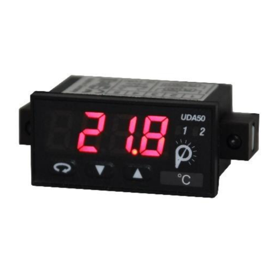
1. Short description 1. Short description The switch panel meter UDA 50...-U... is a 4-digit digital display for measuring various measuring signals such as voltage/current, temperature and frequency. The configuration is done via 3 front keys or by means of an optional PC software PM-TOOL. An integrated programming lock prevents unwanted changes to parameters and can be unlocked again via an individual code. -
Page 6: Assembly
2. Assembly 2. Assembly Please read the safety instructions on page 34 before assembly and keep these instructions for future reference. 1. After removing the fasteners, insert the device. 2. Check seal for good fit. 3. Re-engage fastening elements and tighten clamping screws by hand. Then tighten further by half a turn with the screwdriver.. -
Page 7: Elektrical Connection And Connection Examples
3. Electrical connection 3. Electrical connection 3.1. Pin assignment Type UDA 50...-U... - Supply 9-28 VDC, galvanically not isolated 9-28 VDC Note: < _ 1 VA Clamps 3, 5 and 7 are electrically connected in the device. Signaleingänge Spannungs- Halbleiter- versorgung ausgänge 3.2. - Page 8 3. Electrical connection 2-wire sensor 4-20 mA with external power supply Schaltpunkte GND S2 0/4-20 mA 9-28 VDC Transmitter- versorgung 3-wire sensor 0/4-20 mA Schaltpunkte GND S2 0/4-20 mA 9-28 VDC 3-wire sensor 0/4-20 mA with external power supply Schaltpunkte GND S2 0/4-20 mA 9-28 VDC...
- Page 9 3. Electrical connection 3-wire sensor 0-1/2…10 V Schaltpunkte GND S2 1/2 V 10 V 0-1/2...10 V 9-28 VDC 4-wire sensor 0-1/2…10 V, 50 mV Schaltpunkte GND S2 50 mV 10 V 1/2 V 0-1/2...10 V, 50 mV 9-28 VDC 3-wire sensor 0-1/2…10 V with external power supply Schaltpunkte GND S2 1/2 V...
-
Page 10: Pt100 / Pt1000 / Thermocouple
3. Electrical connection 3.2.2. Temperature Pt100 3-wire Schaltpunkte GND S2 Pt100 9-28 VDC Pt1000 2-wire Schaltpunkte GND S2 Pt1000 9-28 VDC Thermocouple Schaltpunkte GND S2 9-28 VDC... -
Page 11: Frequency / Rotational Speed
3. electrical connection 3.2.3. Frequency / Rotational speed Encoder with TTL output Schaltpunkte GND S2 9-28 VDC Geber Versorgung Encoder with external power supply and TTL output Schaltpunkte GND S2 9-28 VDC Geber Versorgung Geber- versorgung Encoder with PNP output Schaltpunkte GND S2 9-28 VDC... - Page 12 3. electrical connection Encoder with ext. power supply and PNP output Schaltpunkte GND S2 9-28 VDC Geber Versorgung Geber- versorgung Encoder with NPN-output Schaltpunkte GND S2 9-28 VDC Versorgung Geber Encoder with ext. power supply and NPN-output Schaltpunkte GND S2 9-28 VDC Versorgung Geber...
- Page 13 3. electrical connection Encoder with NPN-output and required external resistance Schaltpunkte GND S2 9-28 VDC Spannungs- Geber versorgung Encoder with external power supply, NPN-output and required external resistance Schaltpunkte GND S2 9-28 VDC Spannungs- Geber versorgung Geber- versorgung Encoder with PNP-output and external resistance circuit Schaltpunkte GND S2 9-28 VDC...
-
Page 14: Counter
3. electrical connection Encoder with external supply, PNP-output and external resistance circuit Schaltpunkte GND S2 9-28 VDC Spannungs- Geber versorgung Geber- versorgung Encoder with external supply and namur output Schaltpunkte GND S2 Namur 9-28 VDC Versorgung 3.2.4. Counter When used as a counter, use the connection examples for Frequency/Rotation and the reset input executed below. -
Page 15: Switching Points
3. electrical connection Automatic reset with output 2 and manual reset with external button Schaltpunkte GND S2 Reset 3.3. Switching points Connection examples NPN-output GND switching Relais 9-28 VDC... - Page 16 3. electrical connection Push-Pull-output U and GND-switching 9-28 VDC PNP-output L+-switching 9-28 VDC...
-
Page 17: Functional Description And Operation
4. Functional description and operation 4. Functional description and operation 4.1. Operating and display elements The display has 3 keys with which you can parameterize the device and call up stored functions during operation. Functions that can be adjusted or changed are always signaled with a flashing of the display. -
Page 18: Programming Software Pm-Tool
4. Functional description and operation / 5. Setting the display 4.2. Programming via configuration software PM-TOOL: Part including the software on CD, is a USB cable with device adapter. The connection is established via a 4-pin micromatch connector on the back of the device and to the PC side with a USB connector. -
Page 19: Parameterization
6. Parameterization 6. Parameterization 6.1. Input signal selection: type With the type setting an assignment of the input variant takes place, here can be selected between the five input types voltage, current, Pt100(0), thermocouple and impulse signal. Measurement signal selection Voltage see page 15-18 Power... -
Page 20: Voltage / Current, Volt, Ampe
6. Parameterization 6.1.1. Device parameters for the assignment of voltage/current signals: VoLT, AMPE VoLT: Four voltage signals are available for selection : 0-10 V, 0-2 V, 0-1 V and 0-50 mV AMPE: Here you can choose between the following signals : 0-20 mA and 4-20 mA Parameter Selection option Default... -
Page 21: Setting The End And Start Value, End, Enda, Offs, Offa
6. Parameterization Parameter Selection option Default SPC.A dIS.1 InP.1 dIS.2 InP.2 dIS.3 InP.3 dIS.4 InP.4 diS.5 InP.5 End / OFFS: Measuring range end value / measuring range start value With this pair of values the desired display value is assigned to the measuring signal. If Sen.V or Sen.A was selected as input variant, you can choose between noCA and CAL. -
Page 22: Input Of Support Points For Linearization Of The Measurement Signal, Spc.a
6. Parameterization OVEr: Overflow and underflow behavior The overflow / underflow of the measuring input is displayed with 4 bars at the top or 4 bars at the bottom. The exception is the input type "4-20" (mA) where a measured value smaller than 1 mA is already considered as underflow. -
Page 23: Pt100, Pt1000, Thermocouple, Pt.se, Ther
6. Parameterization 6.1.2. Device parameters for the assignment of Pt100(0), thermocouple: Pt.SE, THEr Pt.SE: Three variants are available: Pt.Lo: Pt100 3-wire -50.0…200.0°C / -58.0…392.0°F Pt.Hi: Pt100 3-wire -200…850°C / -328…1562°F Pt.tH: Pt1000 2-wire -200…850°C / -328…1562°F tHEr: Here we differentiate between : Thermocouple type L, J, K, B, S, N, E, T, R Parameter Selection option Default... -
Page 24: Impulse Measurement, Impu
6. Parameterization 6.1.3. Device parameters for the assignment of pulse signals: IMPU FrEq: Frequency measurement of TTL signals, PNP/NPN sensors. tUrn: Rotational speed measurement (simplified setting option) of TTL signals, PNP/NPN sensors. This function also allows a flow to be scaled. CO.up: Counting input (up-counter) for TTL signals, PNP/NPN sensors. -
Page 25: Impuls Actuation, I.typ
6. Parameterization Parameter Selection option Default dIS.2 InP.2 dIS.3 InP.3 diS.4 InP.4 diS.5 InP.5 I.tYP: Impulse signal The impulse input can be controlled in three different modes. Active TTL signals with approx. 0.8 V lower and approx. 2 V upper threshold. Passive switching contact that switches the internal pull up to ground. -
Page 26: Filter, Filt
6. Parameterization FILt: Limitation of the impulse length For debouncing mechanical contacts via the selection of the filter frequency. none Special evaluation of the impulse length. 2 Hz at duty cycle 1:1 => minimum impulse length 250 ms 5 Hz at duty cycle 1:1 => minimum impulse length 100 ms 10 Hz at duty cycle 1:1 =>... -
Page 27: Rotational Speed, Turn
6. Parameterization 6.1.3.2. Rotational speed measurement Since more than 80% of the applications of a frequency measurement refer to a rotational speed, there is a simplified setting option via the "Turn" type. This function can also be used to scale a flow. -
Page 28: Filter, Filt
6. Parameterization FILt: Limitation of the impulse length For debouncing mechanical contacts via the selection of the filter frequency. none Special evaluation of the impulse length. 2 Hz at duty cycle 1:1 => minimum impulse length 250 ms 5 Hz at duty cycle 1:1 => minimum impulse length 100 ms 10 Hz at duty cycle 1:1 =>... -
Page 29: Up/Down Counter, Co.up, Co.dn
6. Parameterization 6.1.3.3. Up/down counter Parameter Selection option Default IMPu Parameter Selection option Default I.tYP Co.b EdGE PrES FILt End. I.tYP: Impulse signal The impulse input can be controlled in three different modes. Active TTL signals with approx. 0.8 V lower threshold and approx. 2 V upper threshold Passive switching contact that switches the internal pull up to ground. -
Page 30: Counter Base / Impuls Signal, Co.ba
6. Parameterization Co.bA: Counter base By default, the display in counter mode records the incoming impulses. However, the system time in seconds or minutes can also be used as the counter basis. In this case, the impulse input at the gate time, which at flank PoSI (HIGH signal) counts and at LOW stands. At the flank nEGA the logic is reversed. -
Page 31: General Display Parameters
6. Parameterization 6.2. General display parameters Parameter Selection option Default dI.HI dI.Lo tASt FLAS SEC: Measurement timet Setting the base measuring time or the frequency filter for calming the measured value. This filter value can be set from 0.01...2.00 seconds. For impulse measurements, the value can be selected up to 0.00, so that the detection runs at the maximum speed. -
Page 32: Alarm Parameters
6. Parameterization 6.3. Alarm parameters Parameter Selection option Default AI.Fu AI.Er AI.tY AI.LI AI.HY AI.HI AI.Lo AI.oF AI.on A2.Fu A2.Er A2.tY A2.LI A2.H A2.HI A2.Lo A2.oF A2.on... -
Page 33: Limit Value Behavior, A1.Fu, A2.Fu
6. Parameterization A1.Fu, A2.Fu: Limit value behavior With the operating principle it is possible to switch between different working types of the switching outputs. Is Ax.Fu = oFF selected, the associated setpoint parameters are not displayed. The switching point is without function and associated parameters are not displayed (Default state). -
Page 34: Upper Limit, A1.Lo, A2.Lo
7. Reset to default values (factory setting) A1.HI, A2.HI: upper limit value A1.Lo, A2.Lo: lower limit value For the range functions A1.FU, A2.FU = rAnG or Out.r this value defines between „-1999…9999“ the upper/lower limit of the window function. This parameter is not displayed for other operating principles. -
Page 35: Technical Data
8. Technical data 8. Technical data housing dimensions 48x24x52 mm (WxHxD) 48x24x67 mm (WxHxD) including plug-in clamp +0,6 +0,3 Installation cutout 45,0 x 22,2 Wall thickness up to 5 mm Mounting Screw elements Material PC Polycarbonat, black, UL94V-0 Sealing material EPDM, 65 Shore, black Protection class Standard IP65 (front), IP00 (backside) - Page 36 8. Technical data Signal Measuring range measuring range Resolution -170…950°C -274…1742°F Thermo J 1°C / 1°F -270…400°C -454…752°F Thermo T 1°C / 1°F -50…1768°C -58…3214°F Thermo R 1°C / 1°F 80…1820°C 176…3308°F Thermo B 1°C / 1°F Thermo E -270…1000°C -454…1832°F 1°C / 1°F Thermo L...
- Page 37 8. Technical data Memory EEPROM ≥ 100 years at 25°C Data preservation Environmental conditions Working temperature -20°C…+50°C Storage temperature -30°C…+70°C Climatic resistance Relative humidity 0-85% annual average without condensation EN 61326 CE-marking Conformity according to directive 2014/30/EU Safety regulations according to Low Voltage Directive 2014/35/EU EN 61010;...
-
Page 38: Safety Instructions
9. Safety instructions 9. Safety instructions Please read the following safety instructions and assembly chapter 2 before installation and keep these instructions for future reference. Intended use The UDA 50-...-U...is intended for the evaluation and display of sensor signals. In the event of improper use or operation personal injury and / or damage to property may occur. -
Page 39: Troubleshooting
10. Error description 10. Troubleshooting Error description Measures • The input has a very large measured value, check the The device indicates a permanent overflow. measuring distance. • The display range of 999 or the specified measuring range is exceeded, check the interpolation points or selected input types and the signal range. - Page 40 UDA 50-…U…promesstec GmbH Version 2.1.1...
Need help?
Do you have a question about the UDA 50-U Series and is the answer not in the manual?
Questions and answers