
Related Manuals for promesstec UDA 50-A Series


Summary of Contents for promesstec UDA 50-A Series
- Page 1 user manual UDA 50-…-A & -B UDA 50-…B… from page 2 UDA 50-…A… from page 15...
- Page 2 GmbH Niedersachsenstraße 4 D – 48465 Schüttorf Fon: +49 (0)25923 / 90229-0 Fax: +49 (0)25923 / 90229-29 www.promesstec.com user manual UDA 50-…-B-0 Direct current / Direct voltage signals 0-20 mA, 4-20 mA, 0-10 VDC Technical features • red display of -1999…9999 digits (optional: green, orange or blue) •...
- Page 3 Identification STANDARD-TYPE ORDER NUMER Direct voltage / Direct current Articel-no. 99-000949 Housing dimension: UDA 50-2-B-0 48x24 mm Articel-no. 99-001711 UDA 50-3-B-0 Dimension symbols are to specified when ordering, e.g. mbar...
-
Page 4: Table Of Contents
Content Short description Assembly Electrical connection and connection examples Function description and operation 4.1. Programming software PM-TOOL Setting the display 5.1. Switching on 5.2. Standard parameterisation (flat operating level) Value assignment to control the signal input 5.3. Programming lock RUN Activation / Deactivation of the programming interlock or change into extended parameterisation 5.4. -
Page 5: Short Description
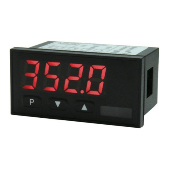
1. Short description 2. Assembly 1. Short description The panel instrument UDA 50 is a 4-digit display for direct voltage / direct current signals and a visual limit value monitoring via the display. The configuration happens via three front keys or via the optional PC- software PM-TOOL. -
Page 6: Electrical Connection And Connection Examples
3. Electrical connection 3. Electrical connection Type UDA 50 – Supply 24 VDC or 12 VDC, galvanically isolated, depending on version, see type code 24 VDC UDA 50-2… 12 VDC UDA 50-3… Connection examples: Below you find some connection examples, which demonstrate some practical applications: In connection with a In connection with a In connection with a... -
Page 7: Function Description And Operation
4. Function description and operation 4. Function description and operation Operation The operation is divided into different levels. Menu level Here it is possible to navigate between the individual menu items. Parameterisation level: The parameters stored in the menu item can be parameterised here. Functions that can be adjusted or changed are always indicated with a flashing of the display. -
Page 8: Setting The Display
5. Setting the display 5. Setting the display 5.1. Switching on After completing the installation, you can put the device into operation by applying the supply voltage. Check all electrical connections once again beforehand to ensure that they are connected correctly. Starting sequence During the switch-on process, the segment test (8 8 8 8), the message of the software type and subsequently the software version are displayed for 1 second for the same time. -
Page 9: Programming Lock Run
5. Setting the display Menu-level Parameterization level Setting the display time SEC: Default: 01.0 dann The display time is set with [▲] [▼]. The jumps are in steps of 0.1 up to 1 second and in steps of 1.0 up to 10.0. With [P] the selection is confirmed and the display changes to the menu level. 5.3. -
Page 10: Zero Point Slowdown Of The Input Signal, Zero
5. Setting up the device Menu level Parameterization level Setting the tara/offset value, TArA: Default: 0 The specified value is added to the linearized value. This is how the characteristic curve can be shifted by the selected amount. Zero point slowdown, ZErO: Default: 0 With zero point calming, a value range around the zero point can be preselected at which the display shows a zero. - Page 11 5. Setting up the device Menu level Parameterization level Hysteresis for limit value, HY-1: Default: 0000 The hysteresis defines a difference to the limit value by which an alarm reacts delayed. Function for limit value undercut/ limit value exceeded, FU-1: Default: hi9h The limit value violation is selected with Louu (for LOW = lower limit value) and that with HiGH (for HIGH = upper limit value).
-
Page 12: Safety Parameter For Locking Of The Programming, Code
6. Reset to default values Menu level parameterization level Setting the code, CODE: Default: 1234 With this setting it is possible to select an individual code (factory setting 1 2 3 4) for the programming lock. For programming lock/unlock please proceed according to menu item run. Number of additional supporting points, SPCt: Default: 0 8 support points can be defined in addition to the start and end values in order to linearize non-... -
Page 13: Alarms / Switching Points
7. Alarms / switching points 7. Alarms / switching points Functional principle of the optical switching points: Limit value exceeded „High“ With the operating current, the switching point S1-S2 is switched off below the switching threshold and is activated when the switching threshold is reached. -
Page 14: Technical Data
8. Technical data 8. Technical data Housing Dimensions 48x24x27 mm (WxHxD) 48x24x54 mm (WxHxD) including plug-in terminal +0,6 +0,3 Mounting cutout 45,0 x 22,2 Wall thickness up to 3 mm Fixing screw element Material PC Polycarbonat, black, UL94V-0 Sealing material EPDM, 65 Shore, black Protection class standard IP65 (front), IP00 (back side) - Page 15 8. Technical data Ambient conditions 0…60°C Working temperature Storing temperature -20…80°C Climatic resistance relative humidity 0-80% on years average without dew EN 61326 CE-sign Conformity to directive 2004/108/EG Safety regulations According to Low Voltage Directive 2006/95/EG EN 61010; EN 60664-1...
-
Page 16: Safety Instructions
9. Safety instructions 9. Safety instructions Please read the following safety instructions and the assembly chapter 2 before installation and keep it for future reference. Intended use The device is intended for the evaluation and display of sensor signals. In the event of improper use or operation personal injury and/or damage to property may occur. -
Page 17: Error Description
10. Error description 10. Error description Error describtion Measures • The input has a very large measured value, The device indicates a permanent overflow. check the measuring distance. • If an input with a small sensor signal is selected, it is only connected on one side or the input is open. - Page 18 GmbH Niedersachsenstraße 4 D – 48465 Schüttorf Fon: +49 (0)25923 / 90229-0 Fax: +49 (0)25923 / 90229-29 www.promesstec.com User manual UDA 50-…-A-0 Technical features: • red display of -1999…9999 digits (optional: green, orange or blue) • minimal installation depth: 27 mm without plug-in terminal •...
- Page 19 Identification STANDARD-TYPE ORDER NUMBER Pt100 2-/3-wire Article-no.: 99-000950 Housing dimension: UDA 50-2-A-0 48x24 mm Article-no.: 99-000975 UDA 50-3-A-0 Dimension symbols are to be specified on request when ordering, e.g. °C...
- Page 20 Content Short describtion Assembly Electrical connection and connection examples Functional description and operation 4.1. Programming software PM-TOOL Setting the display 5.1. switching on 5.2. Standard parametrization (flat operating level) Value assignment to control the signal input, line matching 5.3. Programming lock RUN Activation/deactivation of the programming lock or Change to the extended parameterization 5.4.
-
Page 21: Short Describtion
1. Short describtion 2. Assembly 1. Short describtion The panel meter UDA 50 is a 4-digit display for Pt100 sensors and a visual limit value monitoring via the display. The configuration is done via three front keys or by means of an optional PC software PM-TOOL. An integrated programming lock prevents unwanted changes to parameters and can be unlocked again via an individual code. -
Page 22: Electrical Connection And Connection Examples
3. Electrical connection 3. Electrical connection Type UDA 50 – Supply 24 VDC or 12 VDC, galvanically isolated, depending on version, see type code 24 VDC UDA 50-2… 12 VDC UDA 50-3… Note: In the case of temperature sensors which do not have a galvanic connection to an external potential, the galvanic isolation of the device can be cancelled by a jumper from terminal 3 to 4 and thus stabilize the display against external interference. -
Page 23: Functional Description And Operation
4. Function description and operation 4. Function description and operation Operation: The operation is divided into two different levels. Menu-level: Here you can navigate between the individual menu items. Parameter-level: The parameters stored in the menu item can be parameterized here. Functions that can be adjusted or changed are always signaled with a flashing of the display. -
Page 24: Setting The Display
5. Setting the display 5. Setting the display 5.1. switching on After completing the installation, you can put the device into operation by applying the supply voltage. Check all electrical connections once again beforehand to ensure that they are connected correctly. Start sequence During the switch-on procedure, the segment test (8 8 8 8), the message of the software type and subsequently the software version are displayed for 1 second for the same time. -
Page 25: Programming Lock Run
5. Setting the display Menu-level Parameter-level 5.3. Programming lock RUN Activation / Deactivation of the programming lock and completion of the standard parameterization. run: Default: uloc Here, [▲] [▼] can be used to select between deactivated key lock (factory setting) and activated key lock Loc. -
Page 26: Safety Parameter For Lock Of The Programming, Code
5. Setting the display Menu-level Parameter-level Limit values, LI-1: Default: 0200 The limit value specifies the threshold above which the alarm reacts or is activated / deactivated. Hysteresis for limit values, HY-1: Default: 0000 The hysteresis defines a difference to the limit value by which an alarm reacts delayed. Function for undercutting/exceeding the limit value, FU-1: Default: hi9h The limit value violation is selected with Louu (for LOW = lower limit value) and that with HiGH... -
Page 27: Reset Of Default Value
6. Reset of Default values Menu-level Parameter-level Function for undercutting / exceeding limit value, FU-2: Default: hi9h The limit value violation is selected with Louu (for LOW = lower limit value) and the one with HiGH (for HIGH = upper limit value). Derived from "lower limit" = lower limit value and higher limit = upper limit value. -
Page 28: Alarm / Switching Points
7. Alarms / switching points 7. Alarms / switching points Functional principle of the optical switching points: Limit value exceeded „High“ With the operating current, the switching point S1-S2 is switched off below the switching threshold and is activated when the switching threshold is reached. -
Page 29: Technical Data
8. Technical data 8. Technical data housing dimensions 48x24x27 mm (WxHxD) 48x24x54 mm (WxHxD) including plug-in terminal +0,6 +0,3 Installation cutout 45,0 x 22,2 Wall thickness up to 3 mm Mounting Screw elements Material PC Polycarbonat, black, UL94V-0 Sealing material EPDM, 65 Shore, black Protection class Standard IP65 (front), IP00 (back side) - Page 30 8. Technical data Environmental conditions Working temperature 0°C…60°C Storage temperature -20°C…80°C Climatic resistance relative humidity 0-80% annual average without condensation EN 61326 CE-mark Conformity according to directive 2004/108/EG Safety regulations According to Low Voltage Directive 2006/95/EG EN 61010; EN 60664-1...
-
Page 31: Safety Instructions
9. Safety instructions 9. Safety instructions Please read the following safety instructions and assembly chapter 2 before installation and keep these instructions for future reference. Intended use The UDA 50 device is designed for the evaluation and display of Pt100 signals. In the case of improper use or operation may result in personal injury or damage to property. -
Page 32: Error Describtion
10. Error describtion 10. Error describtion Error describtion Measures • The input has a very large measured value, The device indicates a permanent overflow. check the measuring distance. • The entrance is open. • The input has a very small measured value, The device indicates a permanent underflow.
Need help?
Do you have a question about the UDA 50-A Series and is the answer not in the manual?
Questions and answers