Table of Contents
Advertisement
Quick Links
Advertisement
Chapters
Table of Contents

Related Manuals for BK Medical Falcon Premium 2101EXL


Summary of Contents for BK Medical Falcon Premium 2101EXL
- Page 1 Falcon Premium Extended User Guide Type 2101EXL English BB1737-A October 2007...
- Page 2 B-K Medical representative or by contacting us directly. Scanner Software The Falcon Premium 2101EXL Ultrasound Scanner is closed. Any modification of or installation of software to the system may compromise safety and function of the system. Any modification of or installation of software without written permission from B-K Medical will immediately void any warranty supplied by B-K Medical.
-
Page 3: Table Of Contents
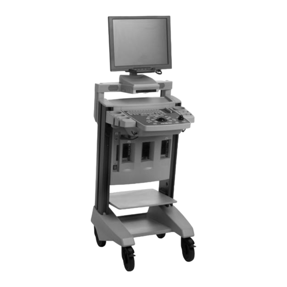
Contents General Information Operation Urology Calculations Cardiac Calculations Obstetrics Calculations M-mode Calculations Care of the Scanner Installation Appendices 1. Keyboard Shortcuts and Functions 2. Setup Overview 3. Urology Calculation Methods 4. Cardiac Calculation Methods 5. Obstetrics Calculation Methods Index... - Page 4 Falcon Premium Front Panel This control is inactive...
- Page 5 About this Guide About this Guide This user guide is for the Falcon Premium 2101EXL Ultrasound Scanner. The scanner is a 2D ultrasound echo and flow imaging system for diagnosis, data processing and transfer and guidance of puncture and biopsy. It is not for continuous operation. This means that we recommend that you turn off the scanner at the end of each workday.
- Page 6 Safety Information Safety Information This user guide contains cautions, warnings and other informa- tion about what you must do to ensure the safe and proper per- formance of the ultrasound scanner. You must also follow local government rules and guidelines at all times. WARNING Warnings contain information that is important for avoiding per- sonal injury.
- Page 7 Safety Information Symbol Name Description Protective Protective ground ground (earth) Type BF BF: Isolated from ground. Maximum patient leakage current under: Normal Condition ≤100µA, Single Fault Condition ≤500µA Type BF BF, defibrillator-proof Type B B: Maximum patient leakage current under: Normal Condition ≤100µA, Single Fault Condition ≤500µA SEALING Dust-and-immersion-protected according to IEC Publication 60529...
- Page 8 CE Marks on Electrical Devices CE Marks on Electrical Devices The European Union has introduced directives requiring b marks on devices. Non medical devices marked with bcomply with relevant direc- tives, for example EEC Council Directive 89/336/EEC of 3 May 1989 concerning Electromagnetic Compatibility.
- Page 9 General Safety Precautions WARNING If at any time the scanner malfunctions or the image is severely distorted or degraded, or you suspect in any way that the scanner is not functioning correctly: • Remove all transducers from contact with the patient. •...
- Page 10 General Safety Precautions Explosion Hazards WARNING The ultrasound scanner is not designed to be used in potentially explosive environments. It should not be operated in the presence of flammable liquids or gases, or in oxygen-enriched atmospheres. There is a possible explosion hazard if the scanner is used in the presence of flammable anesthetic.
- Page 11 General Safety Precautions Anyone using the equipment must be able to recognize the ESD symbol and understand how to take the necessary precau- tionary procedures, as described in the warning below. WARNING Do not touch pins in connectors that have this symbol. Do not connect anything to them unless you follow these ESD (elec- trostatic discharge) precautionary procedures: Discharge your body to ground before you touch the pins with...
- Page 12 • Keep power cables, sockets and plugs clean and dry at all times. Interference The Falcon Premium 2101EXL Ultrasound Scanner is suitable for use in all establishments, other than domestic establishments and those directly connected to the public low-voltage power sup- ply network that supplies buildings used for domestic purposes.
- Page 13 General Safety Precautions Electrical noise WARNING Electrical noise from nearby devices such as electrosurgical devices – or from devices that can transmit electrical noise to the AC line – may cause disturbances in ultrasound images. This could increase the risk during diagnostic or interventional proce- dures.
- Page 14 General Safety Precautions turbances occur, they will appear as white lines in the ultrasound picture and cannot be confused with physiological signals. WARNING Other equipment may interfere with the scanner, even if that other equipment complies with CISPR (International Special Committee on Radio Interference) emission requirements.
- Page 15 General Safety Precautions WARNING Be careful to avoid the following potential sources of injury: • Parts of the body can be pinched by moveable parts of the scanner, such as the front panel, and the monitor. • Tilting the scanner can cause it to be unstable and injure someone.
- Page 16 Acoustic Output WARNING Equipment that complies with the requirements of EN/IEC 60601–1 [2], UL 2601-1 [4] or CSA C22.2 No. 601.1–M90 [5] can be connected to the scanner, but the power for the equipment must come from the auxiliary power output on the scanner or from an independent wall power outlet.
- Page 17 Acoustic Output Prudent Use WARNING Always keep the exposure level (the acoustic output level and the exposure time) as low as possible. Scan patients only when clinical reasons make it necessary. Keep exposure time as short as possible. Be careful to prepare the patient correctly so that you get the best possible image.
- Page 18 Acoustic Output the Output Display Standard. Under Track 3, acoustic output will not be evaluated on an application-specific basis, but the maximum derated Spatial Peak–Temporal Average Intensity ) must be 720mW/cm , the maximum Mechanical Index ≤ SPTA (MI) must be ≤ 1.9, and the maximum Thermal Index (TI) must be ≤...
- Page 19 Acoustic Output is the time-averaged acoustic power of the source or other power parameter (W) is the estimated power necessary to raise the temperature of the target tissue one degree Celsius (W/°C). As a rule of thumb, the Thermal Index (TI) indicates the highest expected temperature increase in degrees Celsius.
- Page 20 Acoustic Output Possibility of Adverse Effects Although it is believed that diagnostic ultrasound causes no sig- nificant biological effects in mammalian tissue [3, 10], the user should be aware of the hypothetical possibilities of adverse effects [11, 13, 14]. Current scientific and clinical concern over possible adverse effects is particularly focused on fetal ultrasound scanning.
- Page 21 Clinical Measurements: Ranges and Accuracies The factory-defined default setup values of acoustic output for each transducer are listed on the Technical Data CD (BZ2100). These setups have been optimized to give the best compromise between low acoustic output and enough power to obtain the image features as quickly as possible.
- Page 22 Clinical Measurements: Ranges and Accuracies ments. This inaccuracy may be further increased by refrac- tion occurring at tissue boundaries. the user can introduce errors when using approximate for- mulas, when positioning the system’s calipers with respect to the ultrasound image and when outlining structures in the image.
- Page 23 Clinical Measurements: Ranges and Accuracies Fig. 2. The dotted line indicates the convex hull of the non-con- vex figure. Measuring volume using a stepping method produces an approx- imation caused by the finite number of steps in the measure- ment. The user must always try to assess how large an inaccuracy is introduced by the selected step size, that is, the dis- tance between organ cross sections.
- Page 24 Clinical Measurements: Ranges and Accuracies rounded to the nearest: 0.01s accuracy: 0.01 x t where t is the full time scale of the image field. References [1] EN 60529:1991 + A1:2000. Specification for degrees of protec- tion provided by enclosures (IP code). [2] EN/IEC 60601-1:1990 +A1:1993+A2:1995+A13:1996 Medical electrical equipment.
- Page 25 Clinical Measurements: Ranges and Accuracies [14] The safety of diagnostic ultrasound. The British Institute of Radiology. 1987. AIUM: American Institute of Ultrasound in Medicine EN: European Standards CSA: Canadian Standards Association IEC: International Electrotechnical Commission NEC: National Electrical Code NEMA: National Electrical Manufacturers Association UL: Underwriters Laboratories Inc., USA Front - xxi...
- Page 26 Clinical Measurements: Ranges and Accuracies Front - xxii...
- Page 27 Section A General Information A.1 Getting Started General Information Turning the Scanner On and Off Adjusting the Front Panel Adjusting the Monitor Position Docking the Flat Screen on Arm Adjusting Monitor Brightness Advanced Display Options Some General Terms F1 – F5 Screen Display Connecting the Palm Control Unit Connecting a Transducer...
- Page 28 A.3 The Front Panel Controls Front Panel and Keyboard Controls Guide Trackball Select Delete Pointer Freeze Zoom Size Copy Split Screen Simultaneous Split Screen Function Puncture Xmit Power M-Line Select Application Distance Label Orientation Bodymark Other Front Panel Controls Foot Switch A.4 Palm Control Unit (PCU) Mouse Stick Selecting a Transducer...
- Page 29 Section A Pointer Distance Color Box/Doppler Gate Range CFM/Power Duplex/Triplex Color Gain Sterile Covers A.5 The Keyboard Patient Identification Partial Reset and Full Reset...
-
Page 31: Getting Started
Section A • Getting Started General Information A A A A.1 Getting Started General Information Before switching on the scanner, make sure that the installation has been approved by a qualified electrical engineer or hospital safety personnel. See “General Safety Precautions” in the intro- ductory section of this user guide. -
Page 32: Adjusting The Monitor Position
Section A • Getting Started The space under the front panel can be used for storage, e.g. gel or paper etc. Adjusting the Monitor Position You can easily adjust the position of the monitor to make scan- ning comfortable for the operator. To Adjust the Height of the Monitor: 1. -
Page 33: Adjusting Monitor Brightness
Section A • Getting Started A A A To Dock the LCD Flat Screen: 1. Standing in front of the scanner, maneuver the flat screen on the arm so that the front of the monitor is over the front of the scanner body. 2. -
Page 34: Advanced Display Options
Section A • Getting Started Test picture Description The test picture has two dark rectanges in the center, one is 2/255 Brightness and the other is 4/255 of 100% white. The test picture has a 100% white square in the center. Contrast Note: Adjusting the contrast can cause problems with the bright- ness range. - Page 35 Section A • Getting Started A A A Gamma settings (gray scales) Three gamma settings are available: B-K gamma 1 – factory default setting recommended by B-K Medical. B-K gamma 2 – the usual gamma setting for the flat screen. B-K gamma 3 –...
-
Page 36: Some General Terms
Section A • Getting Started Some General Terms The following general terms are used to explain the use of the scanner: Soft Menus or Menus These are menus that appear above or below the monitor display. They are easily recognizable by the vertical dividing lines that distinguish the available menu options. -
Page 37: F1 - F5
Section A • Getting Started A A A F1 – F5 The controls F1 through F5 are used to access soft keys. These are menu options that appear on the monitor. For example, when you press the Basic control (Q on the key- board), the menu shown in Fig. - Page 38 Section A • Getting Started Basic Uro- Measure line Basic Uro-pln Uro-Aut Uro-Emp Measure 1 Organ Organ Organ Organ Measure 2 Dist1 Height Height Number Area1 Area1 Measure 3 Dist2 Width Width Step Area2 Area2 Measure 4 Dist3 Length Length Area Volume Volume...
-
Page 39: Connecting The Palm Control Unit
Section A • Getting Started A A A Connecting the Palm Control Unit The Palm Control Unit (PCU) is connected to an adaptor (UA1271) and attached to the RS232 B socket on the rear panel of the scanner. See Section H.13 “Connecting a Palm Control Unit”... -
Page 40: Selecting A Transducer
Section A • Getting Started After connecting the array transducer to the input socket, turn the locking-lever on the transducer’s plug clockwise. Transducer holders are built in to the front panel of the scanner, allowing convenient and secure placement for up to four trans- ducers. -
Page 41: Selecting A Scanning Mode
Section A • Customizing Your System A A A keyboard (the factory default setup shortcut key) to select the crystal for the 2050. 2050 2050 12MHz 16MHz Fig. A10.The menu for Type 2050 Selecting a Scanning Mode The 2101 EXL Premium can scan in the following modes and combinations: B, and B+M (M-mode). -
Page 42: Transducer Setup
Section A • Customizing Your System Parameters marked with a checkbox offer a number of possible selections. Use the g control to step through these. Parameters marked with a checkbox are user-defined text. Use the keyboard to enter text. A user-defined text entry is com- pleted by pressing on the keyboard. - Page 43 Section A • Customizing Your System A A A Fig. A13. Example section of the Transducer Application Setup page 1. Next B Res Horiz Split Page Fig. A14. Transducer Setup menu To save the current settings as an application setup for the selected transducer, activate the appropriate Save in this application field on the Transducer Application Setup page (Fig.
- Page 44 Section A • Customizing Your System Horizontal Split This function enables you to choose a horizontal split screen instead of a vertical split screen (as described in Section A.3). Press Horiz. Split (F2) to toggle the horizontal split screen function on and off.
-
Page 45: System Setup
Section A • Customizing Your System A A A Use Bodymark To set the default bodymark associated with the transducer set- up, move the trackball to the appropriate field on the Transducer Application Setup page (Fig. A13) and press the g control. The Bodymark page is displayed (see later in this Chapter, Fig. -
Page 46: Measure
Section A • Customizing Your System ent levels refer to the size of the zoom box. The factory default level is 2. Use the trackball to select the Zoom Initial Mode field and then use the g control to toggle between the different options. TGC Settings Saved with Application This function allows you to save the TGC (Time Gain Compensa- tion) settings with transducer application data. - Page 47 Section A • Customizing Your System A A A sen. Use the trackball to go to the Auto measure field and press the g control to toggle this function between: Setting Function Auto Calculator and Auto dist turned off Measure Default Calculator function Current calculator function re-enabled when scanner is frozen.
- Page 48 Section A • Customizing Your System BRACHY BRACHY BRACHY UA1232 10mm PROG. Fig. A19. The Puncture soft menu for an 8658 Transducer Use the g control to select the seed matrix spacing and coordi- nates. You can toggle through the following options: 5mm (A..G/1..7) - also selected using F3 as shown in Fig.
- Page 49 Section A • Customizing Your System A A A Caution Prior to seed implantation using the needle guide matrix, the matrix offset value should be checked to make sure it corresponds with the chosen matrix. The matrix alignment should then be checked.
-
Page 50: Display
Section A • Customizing Your System Display Fig. A20. System Setup - Display Hospital ID To enter a hospital identification: 1. Use the trackball to go to the Hospital ID field. 2. Use the keyboard to type in the hospital identification. 3. - Page 51 Section A • Customizing Your System A A A The selected language will become operational after switching off and then re-booting the scanner. Menu Timeout This function will determine how long the soft menus remain on the screen. Use the trackball to go to the Menu Timeout field and press the g control to toggle between Timeout Enabled or Dis- abled.
-
Page 52: Basic Config
Section A • Customizing Your System Basic Config Fig. A21. System Setup - Basic Config Date Format To select the date format use the trackball to go to the Date For- mat field and press the g control to toggle between the differ- ent date formats: YYYY-MM-DD, MM-DD-YYYY or DD-MM- YYYY. -
Page 53: Copy Setup
Section A • Customizing Your System A A A To select the appropriate date/time field use the trackball to go to the Next/Previous, Date/Time fields and press the g control to step through the date and time parameters. Return to the Incre- ment/Decrement Date/Time fields to adjust the value. -
Page 54: Shortcut Setup
Section A • Customizing Your System Shortcut Setup Using this function, you can define a set of shortcut keys to sim- plify the selection of measurement parameters in the Urology and Obstetrics packages and to simplify selecting a scanning mode. There are 2 shortcut setup pages, one for the OB package, and one for urology and other parameters. -
Page 55: Ob Setup
Section A • Customizing Your System A A A Fig. A23. Urology and other parameters shortcut keys setup page The five sections of the space bar (divided by vertical lines) may also be used as five different shortcut keys. You cannot use a key- board key that has been system-predefined for another purpose. -
Page 56: The Front Panel Controls
Section A • The Front Panel Controls A.3 The Front Panel Controls Front Panel and Keyboard Controls Guide The icons on the front panel and the keyboard functions are listed on the Keyboard Control Guide (SC1452) that is included with the scanner. You may find this useful to refer to whilst using the scanner. -
Page 57: Select
Section A • The Front Panel Controls A A A Select The g control is used for selecting markers during measure- ments, for zooming-in on a selected area when the zoom function is active, for updating zoom, and for selecting a label on the mon- itor display. -
Page 58: Mfi
Section A • The Front Panel Controls If an MFI (Multifrequency Imaging) transducer is selected, press the MFI control to step through the frequency options. The selected frequency is then displayed at the top of the screen. Zoom This function is used to zoom into a specific area of the ultra- sound image. -
Page 59: Size
Section A • The Front Panel Controls A A A frame. Pressing the u control or the g control will also zoom in on the selected area. 4. The zoom area can then be moved using the trackball or sized using the up/down control. -
Page 60: Simultaneous Split Screen Function
Section A • The Front Panel Controls To activate Split Screen: 1. Press the control. The left or upper image will be active. 2. Press the control again to toggle between the left and right image (upper and lower image in horizontal split). 3. -
Page 61: Puncture
Section A • The Front Panel Controls A A A Puncture To superimpose a puncture line onto an ultrasound image: 1. Press the D control to activate the default puncture guide for the selected transducer, if applicable. 2. If alternative puncture guides are available for a trans- ducer, a Puncture menu is shown on the monitor. -
Page 62: Xmit Power
Section A • The Front Panel Controls Xmit Power This function is used to select and adjust the Thermal Index Limit (TI). Press the v control to display the Tissue Type menu shown in Fig. A26. Tissue TI Limit Type Fig. -
Page 63: Distance
Section A • The Front Panel Controls A A A Distance Pressing the distance r control on the front panel will place a set of distance markers on the monitor one of which can be moved using the trackball. Pressing the r control again will give extra sets of markers. - Page 64 Section A • The Front Panel Controls Note: A fast-label will not be inserted if the text will coincide with the screen border. When the L control is pressed, either the Label Main menu (Fig. A28) or the Label Library menu (Fig. A29) is displayed on the monitor, depending on your setup.
- Page 65 Section A • The Front Panel Controls A A A 1. Press the Label Library soft key (F1) to select the last used label library. 2. To select another label library, press the Next Library soft key (F1) to toggle between the libraries. 3.
- Page 66 Section A • The Front Panel Controls Fig. A30. Label Setup Page This function allows you to define the initial function of the Label control. You can choose between “label library” or “free text”. When the function is set to “label library”, pressing the L con- trol will access the label library.
-
Page 67: Orientation
Section A • The Front Panel Controls A A A To enable or disable a label library: 1. Use the trackball to point at the activation status (active or inactive). 2. Press the g control to toggle the status between active or inactive. -
Page 68: Bodymark
Section A • The Front Panel Controls If the transducer Type 8551 is selected, F3 can be used to toggle the rotation axis indicator on and off. Fig. A32. The U/D and L/R controls change the orientation of the image Bodymark This function allows you to place a small icon showing a part of the body on the ultrasound image. - Page 69 Section A • The Front Panel Controls A A A Select and Place a Bodymark: Press the m control on the front panel. If no bodymarks have been selected, the last used bodymark library is displayed. See Fig. A33 for an example. Fig.
- Page 70 Section A • The Front Panel Controls The scanning plane indicator can also be rotated by using the trackball. Press the g control and then rotate the plane indica- tor using the trackball. The g control can be used to toggle between moving and rotating the scanning plane indicator.
- Page 71 Section A • The Front Panel Controls A A A Fig. A36. Bodymark Setup Page The name and activation status of each bodymark library can be edited. If a bodymark library is deactivated, its bodymarks will not be displayed for you to choose from. To enable or disable a bodymark library: 1.
- Page 72 Section A • The Front Panel Controls Other Front Panel Controls Description of the use of other front panel controls including measure, angle, image, focus, gain, storage, review can be found in Section B. Foot Switch There is a two pedal foot switch that can be used for operating different functions on the scanner.
- Page 73 Section A • Palm Control Unit (PCU) A A A A.4 Palm Control Unit (PCU) An optional Palm Control Unit (PCU) can be used for remote operation of the scanner (see Fig. A38). Fig. A38. Palm Control Unit Note: The PCU should not be used, in particular the mouse stick should not be touched, for 12 seconds after the scanner has been turned on (or after connection to the scanner).
- Page 74 Section A • Palm Control Unit (PCU) See in Section A.1 “Getting Started” for further details on trans- ducer selection. Select Application (Appl) The PCU control has the same function as the Appl control on the front panel. See Section A.3 “The Front Panel Controls”. Puncture Press the D control to activate the default puncture guide for the selected transducer.
- Page 75 Section A • Palm Control Unit (PCU) A A A B Gain Press the up/down control to increase or decrease the gain of the entire B-mode image. For a more detailed description of the Gain and TGC (Time Gain Compensation) controls, See Section B.1 “B-mode Imaging”. Freeze The PCU control has the same function as the I control on the front panel.
- Page 76 Section A • The Keyboard Color Gain This control cannot be used with this scanner. Sterile Covers Sterile covers are available for use with the PCU. The procedure for fitting the sterile covers is shown in Section G.2 “Disinfec- tion”. A.5 The Keyboard Patient Identification To enter a new patient identification:...
- Page 77 Section A • The Keyboard A A A Partial Reset and Full Reset Partial Reset (F4) can be used to accept a new ID while retaining the image settings, for example, the image parameters and body- mark selection. However, the scanner is reset to B-Mode and all measurements will be cleared.
- Page 78 Section A • The Keyboard A - 48...
- Page 79 Section B Operation B.1 B-mode Imaging B Gain/TGC Image Persistence Rate Strong and Composite Focus B.2 B+M-mode Setting Thermal Indices M Gain Adjusting the Gray Scale Sweep Speed B.3 Making a Measurement Distance The Measure Menu Angle Draw Volume Ellipse Circle Heart Rate (HR) B.4 Image Review...
-
Page 81: B-Mode Imaging
Operation Section B • B-mode Imaging B.1 B-mode Imaging The B/M control on the front panel is used for toggling between B B B B and B+M-mode. When in B-mode, you can also press <M> on the keyboard to go to M-mode. When in M-mode, you can also press <B>... -
Page 82: Image
Section B • B-mode Imaging Image Press the front panel f control. The soft menu shown in Fig. B1 is displayed on the monitor. Contrast Contour Gray Scale Fig. B1. The Image soft menu Contrast The contrast function lets you select a contrast setting for the ultrasound image. -
Page 83: Strong And Composite Focus
Section B • B+M-mode or number of images per second. Increasing the frame rate increases the update rate for the ultrasound image. For array transducers, the frame rate is increased by narrowing B B B the scanning field. Press the B up/down control on the front panel to adjust the frame rate. -
Page 84: Setting Thermal Indices
Section B • B+M-mode keyboard to go to B+M-mode. When in B+M-mode, you can also press <B> on the keyboard to go to B-mode. Setting Thermal Indices The Xmit Power function is used to select and adjust the thermal index limit (TI). Press v to display the Thermal Index menu shown in Fig. -
Page 85: Sweep Speed
Section B • Making a Measurement Press the Gray Scale soft keys (F4 and F5) to toggle between 3 different gray scales. The selected gray scale is momentarily dis- played after pressing Gray Scale. The number of the currently selected gray scale is shown on the soft key. B B B Note: The B-mode gray scale can only be changed when scanning in B-mode alone (see Section B.1 “B-mode Imaging”). - Page 86 Section B • Making a Measurement To measure distances: 1. Press r. The first distance measure ( ) will automatically × be activated and ready to be moved. 2. Use the trackball to move the active marker. 3. When the marker is in the desired position, press the g control or the r control.
-
Page 87: Hwl
Section B • Making a Measurement Press the appropriate F key to select the type of measurement you want to make. Note: The Basic Measure main menu can also be accessed by B B B using the Calculator control , provided that the Default Calculator Button function is set to Basic. -
Page 88: Angle
Section B • Making a Measurement To change the factor that is used in the HWL calculation: 1. Press Factor (F4). 2. Enter the new factor using the keyboard and press For more detailed information on using HWL in urology calcula- tions, see Section C.1 “Urology Measurements”. -
Page 89: Draw
Section B • Making a Measurement To stop the angle measurement, press the soft key (F2) again. The angle measurement is also turned off when the distance markers are removed. B B B Draw To use the Draw function with the trackball: 1. - Page 90 Section B • Making a Measurement 2. Use the soft keys (F3 and F4 in the Draw/Vol- ume menu in Fig. B6) to choose the angle for the rotation axis. 3. The volume is calculated and displayed on the monitor. Note: The axis of rotation has a considerable influence on the calculated volume, refer to Fig.
-
Page 91: Ellipse
Section B • Making a Measurement Ellipse The ellipse function enables you to you make mean diameter and circumference measurements on elliptic-shaped structures B B B thereby enabling the calculation of the area and volume. 1. Press the soft key (F4 on the Basic Measure menu). An end-point marker (one of the end-points of the ellipse) appears on the screen and is ready to be moved. -
Page 92: Heart Rate (Hr)
Section B • Making a Measurement 3. Press the g control to obtain the other marker. At this point the circle is shown. 4. Use the trackball to move the second marker, and thus adjust the size of the circle. You can toggle between the markers by pressing the g control repeatedly. -
Page 93: Image Review
Section B • Image Review To reposition a marker, use the g button to toggle between the markers. To delete the heart rate measurement, press HR (F1) for more B B B than one second. To return to the Measure main menu, press To remove all measurements, press the Basic control (Q on the keyboard) for more than 1 second. - Page 94 Section B • Image Review Floppy Duration disk Fig. B9. The review soft menu (note that the floppy disk option is not active) Press the Duration (F1) soft key to determine over what length of time images can be reviewed. To do this you can choose how often images are saved.
- Page 95 Section C Urology Calculations C.1 Urology Measurements Getting Started Urology Shortcut Keys Manual Planimetry Automatic Planimetry Empirical Method C.2 Urology Reports Displaying a Report Editing a Report Printing a Report Resetting...
-
Page 97: Urology Measurements
Urology Calculations Section C • Urology Measurements C.1 Urology Measurements The Urology package contains the measurement and calculation tools and the report facilities for the calculations used in urology. Getting Started Press the Uro control (<W> on the keyboard) to display a Urology calculation menu (see Fig. -
Page 98: Hwl
Section C • Urology Measurements HWL is a measurement method which uses height, width and length measurements to calculate a volume. To calculate an HWL volume, press F2 to display the HWL menu (Fig. C2). Press the Organ soft key (F1) to select an organ; your selection is shown within the HWL menu. -
Page 99: Manual Planimetry
Section C • Urology Measurements Press the HWL (F2) soft key for more than one second to remove the measurement from the screen and the report. Press to go back to the Urology main menu. Manual Planimetry For this method, a number of parallel B-mode images are recorded which cover the organ to be measured. - Page 100 Section C • Urology Measurements 1. From the Urology calculation menu (see Fig. C1) and press Planimetry (F4) to display the Planimetry menu (see Fig. C4). Step Organ Reset Size Fig. C4. The planimetry menu 2. Press the Step Size soft key (F4), then use the keyboard to enter a step size that matches the displacement of the transducer between measurements.
-
Page 101: Automatic Planimetry
Section C • Urology Measurements 4. Press the soft key (F3). An end-point marker (one of the end-points of the ellipse) appears on the screen and is ready to be moved. 5. Use the trackball to move the end-point marker to one end of the organ or structure. - Page 102 Section C • Urology Measurements Organ Fig. C5. The Automatic Planimetry menu When making measurements for automatic planimetry, you can choose between the Draw function or the ellipse function Note: For automatic planimetry calculations, the transverse out- lined area must represent the shape of the organ. Draw To perform automatic planimetry using the Draw function: 1.
-
Page 103: Empirical Method
Section C • Urology Measurements 2. Use the trackball to move the end-point marker to one end of the organ or structure. 3. Press the g control to obtain the other end-point marker, then use the trackball to move it. 4. - Page 104 Section C • Urology Measurements The empirical method is only valid for the bladder. Use the Organ soft key (F1) to select the bladder. Press the Empiric soft key (F4) to display the Empirical menu shown in Fig. C6. Organ Fig.
- Page 105 Section C • Urology Measurements Ellipse To perform empirical method calculations using the Ellipse func- tion: 1. Press (F4) to make an ellipse measurement on a trans- verse image. An end-point marker (one of the end-points of the ellipse) appears on the screen and is ready to be moved. 2.
-
Page 106: Urology Reports
Section C • Urology Reports C.2 Urology Reports Displaying a Report Press the Report soft key (F5) on the Urology main menu to display a report and the Urology Report menu shown in Fig. C7. Organ Remark Const Index Fig. C7. The Urology Report menu The report will show the latest performed measurement on a selected organ. -
Page 107: Resetting
Section C • Urology Reports Resetting To reset all urology measurements and clear the report, press the Uro control (<W> on the keyboard) for more than 1 second, or enter a new patient ID. C - 11... - Page 108 Section C • Urology Reports C - 12...
- Page 109 Section D Cardiac Calculations D.1 Cardiac Calculations Introduction Definitions Heart Rate (HR) Measurement Getting Started End-diastolic Long Axis (EdL) and End-systolic Long Axis (EsL) Measurement End-diastolic Area (EdA) and End-systolic Area (EsA) Measurement D.2 Cardiac Reports Displaying a Report Editing a Report Printing a Report Resetting...
-
Page 111: Cardiac Calculations
Section D • Cardiac Calculations Cardiac Calculations D.1 Cardiac Calculations Introduction A number of measurements can be made on the left ventricle of the heart while scanning in B-mode or M-mode; calculations are then possible using these measurements. Depending on the scan- ning mode you are using, you will find instructions for making the measurements in the following sections: B-mode in this sec- tion and M-mode in Section F.1 “M-mode Measurements”. -
Page 112: Definitions
Section D • Cardiac Calculations Definitions Possible Measurements End-diastolic long axis End-diastolic area End-systolic long axis End-systolic area Heart rate Fig. D2. Possible Measurement definitions Calculations End-diastolic volume Volume of the left ventricle at end-diastole End-systolic volume Volume of the left ventricle at end-systole Stroke volume (beat vol- The amount of blood that flows through a cardiac valve during ume) -
Page 113: End-Diastolic Long Axis (Edl) And End-Systolic Long Axis
Section D • Cardiac Calculations Press the Car control (<R> on the keyboard) to display the Car- diac main menu (see Fig. D4), and press the soft keys to select a measurement method (F1 - F4) or a report (F5). Report Fig. -
Page 114: End-Diastolic Area (Eda) And End-Systolic Area (Esa) Measurement
Section D • Cardiac Reports End-diastolic Area (EdA) and End-systolic Area (EsA) Mea- surement To measure EdA: 1. Press F2. A marker appears on the monitor. 2. Use the trackball to move the marker to the desired start- ing point. 3. -
Page 115: Editing A Report
Section D • Cardiac Reports Editing a Report Note: If the height and weight of the patient has already been entered in the M Calc Report menu (see Section F.2 “M-mode Reports”), those values will be shown here. Press the Height soft key (F1 on the Cardiac Report menu) and use the keyboard to type in the patient’s height. - Page 116 Section D • Cardiac Reports D - 6...
- Page 117 Section E Obstetrics Calculations E.1 General Information E.2 Operation Getting Started Fetal Growth Trend Measuring a Parameter Results Expected FW E.3 OB Setup Getting Started Other Calculations and Parameters User Defined Methods E.4 OB Reports Displaying a Report Displaying a Curve Editing a Report Bioprofile Printing a Report...
-
Page 119: General Information
Obstetrics Calculations Section E • General Information E.1 General Information The Obstetrics (OB) Calculations function offers facilities for cal- culating the gestational age by ultrasound (GAu), clinical gesta- tional age (GAc) based on LMP or an earlier measurement, fetal weight (FW), and expected day of confinement (EDC). The calcu- lations are based on measurements made on a recorded B-mode image and the date of the patient’s last menstrual period (LMP). -
Page 120: Operation
Section E • Operation ATD – abdominal transverse diameter APD – abdominal anterior-posterior diameter MAD – Mean abdominal diameter FL/BPD – femur length to biparietal diameter ratio (ATD + APD)/2 HC/AC – head circumference to abdominal circumference BPD – biparietal diameter ratio HC –... -
Page 121: Lmp
Section E • Operation Fig. E2 shows an example of a setup for the OB main menu. The soft keys F2 – F4 contain the parameters relevant for the calcula- tion methods. Note: If you define your own setup (see Section E.3 “OB Setup”), within the OB main menu, the soft keys F2 –... -
Page 122: Fetal Growth Trend
Section E • Operation LMP menu page is automatically activated after entering a new patient ID. Fetal Growth Trend You can also enter information about previous examinations to produce a fetal growth trend. On the LMP page (Fig. E3), use the trackball to go to the previ- ous examination date field and enter the date of the patient’s last examination using the keyboard. -
Page 123: Measuring A Parameter
Section E • Operation Measuring a Parameter Distance After selecting a function on the OB main menu, a soft menu is shown on the monitor as shown in Fig. E5. To enter a distance measurement, press the soft key corresponding to the parameter you want to measure. - Page 124 Section E • Operation cates the position of the parameter being measured and the cor- responding GAc. If the cursor appears to the right or left of the graph, the measured value is outside the defined range. Results are shown on the monitor and entered into the report. Press on the control panel to return to the OB main menu.
-
Page 125: Results
Section E • Operation To make a circumference measurement using the ellipse function 1. Press the soft key for the parameter you want to mea- sure (F2 for AC, F4 for HC). An end-point marker (one of the end-points of the ellipse) appears on the screen and is ready to be moved. -
Page 126: Ob Setup
Section E • OB Setup E.3 OB Setup Getting Started Press Setup on the front panel to display the Setup menu shown in Fig. A11 in Section A. Press OB Set up (F5) to display the OB setup menu (Fig. E7) and an overview of the current OB setup (Fig. - Page 127 Section E • OB Setup If the OB calculation package is ON, changing any parame- ters in OB Setup will turn off OB Calc and any report data will be lost. The OB Set up menu (Fig. E7) enables you to select calculation methods and measurement parameters for gestational age (GA) and fetal weight (FW).
- Page 128 Section E • OB Setup Fig. E9. GA Method/Parameter Combinations page To select FW calculation methods, press the FW soft key (F3 as shown in Fig. E7). A table of available combinations of methods and measurement parameters is displayed on the monitor (Fig. E10).
- Page 129 Section E • OB Setup Fig. E10.FW method/parameter combinations You can only select one method for calculating FW. To select a method/parameter, move the trackball to highlight the required selection and use g to toggle the selection on and off, as described in Section A.1 “Getting Started”. The page can be extended to include one user-defined method.
-
Page 130: Other Calculations And Parameters
Section E • OB Setup Other Calculations and Parameters To select other calculation methods, press the Other Params soft key (F4 in Fig. E7). A page of available combinations of methods and measurement parameters is displayed on the monitor (Fig. E11). To select a method/parameter, move the trackball to highlight the required selection and use g to toggle the selection on and off. -
Page 131: User Defined Methods
Section E • OB Setup function will automatically calculate FW using the Warsof method (when the measured parameters are within the defined Warsoff range). A table of parameter dependencies is also displayed. You can tog- gle between the different dependencies for AC, AD, CI and HC by moving the trackball to highlight the required field and using g to toggle between the different parameter dependencies available (see Fig. - Page 132 Section E • OB Setup User-Defined GA Method To enter the name of the method, use the trackball to select the name field, and use the keyboard to enter the new method name or edit an existing name. To define the method, use the trackball to select the method field and press g A list of selectable parameters is displayed (Fig.
- Page 133 Section E • OB Setup played on the screen showing the parameter method type (e.g. GAu). The corresponding values can be entered using the key- board. Fig. E15. Example section of the Enter Table Values page Accept Fig. E16. The Enter table values menu When you have entered the values, press Accept (F1) on the soft menu Fig.
- Page 134 Section E • OB Setup To define the method, use the trackball to select the method field and press g . The Fetal Weight Equation definition page is dis- played, see Fig. E17. Fig. E17. Fetal Weight Equation definition page The FW Equation soft menu is also displayed, see Fig.
- Page 135 Section E • OB Setup To define the method, use the trackball to select the method field and press g . The Fetal Weight Equation definition page is dis- played, see Fig. E17. Fig. E19. Fetal Weight Equation definition page The FW Equation soft menu is also displayed, see Fig.
- Page 136 Section E • OB Setup Operator Example of use Addition 2 + 5 Subtraction 6 - 5 Multiplication 6 * 5 Division 6.3 / 5 Square root sqrt() sqrt(21.34) Exponential 3.4^2.1 Natural logarithm log() log(29.4) Inverse logarithm alog() alog(0.6931) Parenthesis 2 + (FL * 8.5) Power of 10 1.3E2...
- Page 137 Section E • OB Reports The following examples show two different formulas and how you would enter them into the scanner. Example 1 × × 2.695 0.253 AC 0.00275 – is entered as FW = 2.695+0.253*AC - 0.00275*AC^2 Example 2 ×...
-
Page 138: Displaying A Curve
Section E • OB Reports If there is more than one page of report text, press the Report soft key (F1 on the OB Report menu) to toggle through the pages. Displaying a Curve Press the Curves soft key (F2) to display the GA curve. An example of a GA curve is shown in Fig. -
Page 139: Editing A Report
Section E • OB Reports Note: GAc is used as a reference for the GA curves. Therefore, there must be an LMP, or the entry of an earlier result, to obtain GA curves. Fetal Growth Trend If you have entered information about previous examinations and measurements (see Fig. -
Page 140: Printing A Report
Section E • OB Reports Score Biophysical Profile Reactive heart rate Gross fetal movements Fetal breathing movement Fetal tone Amniotic fluid volume Placenta Total Fig. E25. Biophysical profile parameters Press Next (F1) on the Biophysical profile menu in Fig. E24 to tog- gle between the different biophysical parameters. - Page 141 Section F M-mode Calculations F.1 M-mode Measurements Introduction Definitions Heart Rate (HR) Getting Started Basic Measurements (Basic) Left Ventricle (LV) Study Mitral Valve (MV) Study Aortic Valve (AO) Study F.2 M-mode Reports Displaying a Report Editing a Report Printing a Report Resetting...
-
Page 143: M-Mode Measurements
M-mode Calculations Section F • M-mode Measurements F.1 M-mode Measurements Introduction There are a number of measurements possible on a frozen M- mode recording. The measurements are divided into Basic, Left Ventricle, Mitral Valve and Aortic Valve studies. If the measure- ments have been made, they will be included in the reports. -
Page 144: Definitions
Section F • M-mode Measurements Definitions Possible Measurements Left ventricle diastolic internal diameter Left ventricle systolic internal diameter Left atrium diameter Aortic root diameter Heart rate Fig. F2. Measurement definitions Calculations End-diastolic volume Volume of the left ventricle at end-diastole End-systolic volume Volume of the left ventricle at end-systole Stroke volume (beat vol-... -
Page 145: Getting Started
Section F • M-mode Measurements Getting Started Record and freeze an M-mode image. Press the Car control (<R> on the keyboard) to display the M Calc main menu (see Fig. F4), and press the soft keys to select a measurement method (F1 - F4) or a report (F5). -
Page 146: Left Ventricle (Lv) Study
Section F • M-mode Measurements To delete a distance measurement, press F1 for more than 1 sec- ond, or press the q control while the distance measurement is selected. Press to go back to the M Calc main menu. Basic Measurement 2 ( ‡... -
Page 147: Mitral Valve (Mv) Study
Section F • M-mode Measurements 3. When the marker is in the desired position, press F2 (LV) or the g control. The other marker is now identified by two + hairline cursors. 4. Use the trackball to move the highlighted marker to the minimum IDd. -
Page 148: Aortic Valve (Ao) Study
Section F • M-mode Measurements To reposition one of the markers, select it by pressing the g control (or F3) to toggle between them. Use the trackball to move the marker. To remove the markers, press F3 (MV) on the M Calc main menu (Fig. -
Page 149: M-Mode Reports
Section F • M-mode Reports AOD, AVD and LAD: If the RVOD markers have been positioned and F2 (AOD) on the AV menu (Fig. F7) is pressed, the AOD markers will be in line (ver- tically) with the RVOD markers. To make similar measurements for the other parameters, press F2 (AOD), F3 (AVD) or F4 (LAD) and follow the instructions for the RVOD measurement. -
Page 150: Printing A Report
Section F • M-mode Reports Printing a Report While the report is displayed on the monitor, press the o con- trol to print the report via a connected video printer. Resetting To reset the M Calc measurements (except the height and weight) and clear the report, press the Car (<R>... - Page 151 Section G Cleaning, Disinfection and Storage G.1 Cleaning Scanner Unit and Keyboard Palm Control Unit (PCU) Transducers and Puncture Attachments G.2 Disinfection Scanner Unit and Keyboard Palm Control Unit (PCU) Summary of Disinfection/Sterilization Methods Storage G.3 Maintenance Scanner Maintenance Palm Control Unit Maintenance Transducer Maintenance G.4 Disposal of the Scanner References...
-
Page 153: Cleaning
Cleaning, Disinfection and Storage Section G • Cleaning G.1 Cleaning To ensure the best results when using B-K Medical equipment, it is important to maintain a strict regular cleaning routine. WARNING Users of this equipment have an obligation and responsibility to provide the highest degree of infection control possible to patients, co-workers and themselves. -
Page 154: Palm Control Unit (Pcu)
Section G • Disinfection The trackball can also be removed for cleaning. See Section A.3 “The Front Panel Controls” for instructions on loosening the trackball using the trackball tool (QA0228). Although the surface of the machine is resistant to many chemi- cals, avoid using strong chemicals as they can discolor it. -
Page 155: Scanner Unit And Keyboard
Section G • Disinfection Specifications for the scanner can be found in the Product Data sheet (BP0127) that accompanies this user guide. Please refer to the Transducer Care, Cleaning & Safety manual for instructions for disinfecting transducers and puncture attach- ments. - Page 156 Section G • Disinfection Caution: Before immersing, the water-tight plug cover must be screwed tightly on to the PCU’s plug. If fluid comes into contact with the plug, the PCU may be destroyed. Fig. G3. PCU’s plug with water-tight cover screwed tightly on ®...
-
Page 157: Summary Of Disinfection/Sterilization Methods
Section G • Disinfection Caution: The watertight PCU plug cover MUST be screwed on while the ® PCU undergoes the STERIS SYSTEM 1 process. Ethylene Oxide Gas After the PCU has been cleaned as described in Section J.1, it can be processed using ethylene oxide gas. WARNING When using ethylene oxide, always follow the manufacturer’s directions for use and the instructions regarding personal protec-... -
Page 158: Maintenance
Section G • Maintenance G.3 Maintenance Scanner Maintenance In order to ensure the stability and performance of the scanner, it is recommended that preventive maintenance should be per- formed once a year. This must be carried out by a B-K Medical technician or a suitably qualified engineer. -
Page 159: Transducer Maintenance
Section G • Disposal of the Scanner appearance of a grayish color, the unit must be checked by a B-K Medical service representative before using it. The outside surface of the watertight plug cover may, after repeated disinfection, change color slightly. This does not repre- sent any problem. - Page 160 Section G • Disposal of the Scanner [3] UL 2601-1:2003 Medical Electrical Equipment – Part 1. Gen- eral Requirements for safety. [4] CSA C22.2 No. 601.1–M90:2001 Medical Electrical Equip- ment – Part 1. General Requirements for safety. G - 8...
-
Page 161: Installation
Section H Installation Installation of the scanner must only be carried out by a qualified engineer who is familiar with IEC 60601–1 (Medical Electrical Equip- ment) and applicable local safety regulations. More comprehensive technical information is included in the separate service manual, which is available on request. - Page 162 H.8 Documentation Trigger H.9 Symbols used for Connections H.10Connecting Video Documentation Equipment Typical setup of documentation equipment S-VHS Sockets RGBS Sockets VGA Sockets H.11Foot Switch Socket H.12Configuration Switch H.13Connecting a Palm Control Unit H.14Adjusting the Shelf Adjusting the Height Adjusting the Depth Adjusting the Angle H.15Tidying the Cables H.16Dismantling the Scanner for Transportation...
-
Page 163: Introduction
Installation Section H • Introduction H.1 Introduction This chapter contains information about electrical requirements and operating conditions for the scanner as well as important information about attaching other equipment. Before you switch on the scanner, make sure that the installation has been approved by a qualified service technician or by hospital safety personnel. -
Page 164: Mains Voltage
Section H • Mains Voltage H.3 Mains Voltage Before use, the Mains Voltage Selector on the back of the scanner (Fig. H1) must be set to match the voltage of the AC mains power supply being used. The scanner is able to operate in two different AC voltage ranges;... -
Page 165: Fuses
Section H • Fuses Caution: Do not switch the scanner on and off repeatedly in quick succes- sion. Doing so may damage the equipment. WARNING Turn off the scanner and unplug the power cord from the mains power supply (the wall outlet) before changing voltage or per- forming any repairs to the system. -
Page 166: Power Supply Cord
Section H • Power Supply Cord H.5 Power Supply Cord The scanner is supplied with a power supply cord that is specific to your region. WARNING Use only the power supply cord that comes with the scanner. Never use extension cords. The increased length of the cord will increase the resistance of the protective ground conductor and may increase the equipment’s leakage current beyond an accept- able level. -
Page 167: Connecting Other Equipment
Section H • Connecting Other Equipment H.7 Connecting Other Equipment For important safety information about connecting other equip- ment, see “Connecting Other Equipment” in the first section of this user guide. WARNING When you connect other equipment that uses the line voltage (such as a video printer, video recorder or other documentation device) to the scanner, the connections must follow the guidelines given in EN 60601–1–1 [1]. -
Page 168: Additional Protective Ground And Potential Equalization
Section H • Connecting Other Equipment Additional Protective Ground and Potential Equalization An additional ground can be connected to the terminal, see Fig. H4. The potential equalization terminal is connected to the scan- ner chassis. It can be connected to corresponding terminals on other equipment to eliminate potential differences. -
Page 169: Documentation Trigger
Section H • Documentation Trigger Fig. H5. RS232 sockets H.8 Documentation Trigger The Documentation Trigger socket (Fig. H6) on the scanner’s rear panel permits control of selected documentation accessories. Fig. H6. The Documentation Trigger socket H - 7... -
Page 170: Symbols Used For Connections
Section H • Symbols used for Connections The pin configuration is shown in Fig. H7. Fig. H7. Pin configuration of the Documentation Trigger socket (external view) When the copy function is activated, the relay short-circuits pins 1, 5, 6 and 8 to pins 2, 3, 4 and 7. Note: Maximum load on the relay must not exceed 10W, 100V and 0.5A. - Page 171 Section H • Symbols used for Connections Symbol Description Composite Out B/W Composite Out Color Composite In Color Fuses Documentation trigger (Copy) RS232 connection Monitor Lightpen socket (lightpen UA1209 no longer available) Mechanical transducer socket Front panel cable socket Foot switch Audio S-VHS in S-VHS out...
-
Page 172: Equipment
Section H • Connecting Video Documentation Equipment H.10 Connecting Video Documentation Equipment The video documentation sockets are shown in Fig. H9. VGA sockets Fig. H9. The video documentation sockets The symbols used on the back panel are shown in Fig. H8. H - 10... - Page 173 Section H • Connecting Video Documentation Equipment Standard video documentation equipment (e.g. a standard VCR) can be connected to the Composite Out socket. For playback from a standard VCR, the Composite In socket should be used. A S-VHS video recorder can be connected to the S-VHS Out socket and can be played back through the S-VHS In socket.
-
Page 174: Typical Setup Of Documentation Equipment
Section H • Connecting Video Documentation Equipment Typical setup of documentation equipment Fig. H10. Suggested setup for documentation equipment showing the required cable sets The diagram in Fig. H10 shows a color video printer connected to the RGBS out socket with the b/w video printer connected to the Composite out socket (with switch set to the left) and the S-VHS VCR connected to the S-VHS Out and In sockets. -
Page 175: Rgbs Sockets
Section H • Connecting Video Documentation Equipment The pin configuration of the S-VHS sockets are shown in Fig. H11. Fig. H11. Pin configuration of the S-VHS Sockets For the S-VHS sockets, pin 3 is S-VHS (Y) and pin 4 is S-VHS (C). Pins 1 and 2 are earth connections. -
Page 176: Vga Sockets
Section H • Connecting Video Documentation Equipment Function Green Blue Ground Synchronization Fig. H13. Pin definitions of the RGBS In socket Function 1,11 2, 4 Green 3,12 Blue 5,6, Ground 7,8,10 13, 15 Synchronization Fig. H14. Pin definitions of the RGBS Out socket Note: Only one piece of external equipment can be connected to the RGBS Out socket. - Page 177 Section H • Connecting Video Documentation Equipment Fig. H15. Pin configuration of the VGA sockets Pin definitions for these sockets are given in Fig. H16. Function Green Blue Ground 13, 14 Synchronization Fig. H16. Pin definitions of the VGA sockets H - 15...
-
Page 178: H.11Foot Switch Socket
Section H • Foot Switch Socket H.11 Foot Switch Socket This socket is for the connection of the optional foot switch. Fig. H17. Foot switch socket The pin configuration of this socket is as follows: Fig. H18. Pin configuration of the foot switch socket Right switch Reserved Left switch... -
Page 179: H.12Configuration Switch
Section H • Configuration Switch H.12 Configuration Switch The Config. switch (see Fig. H20) lets you select the language for the monitor display, a TV standard and the RS232 channel set- ting. Config. Fig. H20. The Config. switch WARNING Turn off the scanner and unplug the power cord from the mains power supply (the wall outlet) before changing the switch settings or performing any repairs to the system. -
Page 180: H.13Connecting A Palm Control Unit
Section H • Connecting a Palm Control Unit The selected switch settings will become operational after switching off and then re-booting the scanner. H.13 Connecting a Palm Control Unit WARNING Make sure that the PCU is labeled UA1270. If you use a different model of PCU, pressing the keys will not have the function you expect. - Page 181 Section H • Connecting a Palm Control Unit Connect the PCU to the adaptor, ensuring that the two dots are lined up (see Fig. H22). Fig. H22. Palm Control Unit connected to adaptor UA1271 The adaptor connects to the RS232 B socket on the special rear panel of the scanner, designed for use with the PCU (see Fig.
-
Page 182: H.14Adjusting The Shelf
Section H • Adjusting the Shelf Caution: A specially-designed rear panel is required to connect adaptor UA1271 to the scanner. The rear panel is included as part of the Palm Control Unit kit (UA1270-K). Contact your local B-K Medi- cal representative for further information. Note: The PCU should not be used, in particular the mouse stick should not be touched, for 12 seconds after the scanner has been turned on. -
Page 183: Adjusting The Depth
Section H • Tidying the Cables holes and the shelf. A further choice of heights is obtained by using the bracket the other way up. Adjusting the Depth There are three holes on each side of the shelf which allow two different depth positions. - Page 184 Section H • Tidying the Cables Fig. H25. Rear side view showing the cable spiral in the groove Any excess cable length can be accommodated in the cable shelf. The cable shelf is located under the back panel. Cable Shelf Fig.
-
Page 185: H.16Dismantling The Scanner For Transportation
Section H • Dismantling the Scanner for Transportation H.16 Dismantling the Scanner for Transportation The front panel, monitor and monitor base can be removed to make it easier to transport the scanner (see Fig. H30). Removing and Replacing the Monitor To Remove the LCD Flat Screen Monitor From the Base: 1. -
Page 186: Removing And Replacing The Monitor Base
Section H • Dismantling the Scanner for Transportation 3. Slide the monitor onto the base, making sure that it is securely and completely on the base and is not crooked. 4. Tighten the thumb screws until the flat screen is secured, or tighten the metal screws using an Allan key. -
Page 187: Front Panel
Section H • Dismantling the Scanner for Transportation 5. Tighten the black screws. 6. Replace the sliding covers. 7. Reconnect the monitor and base to the scanner. Fig. H28. Removing the keyboard prior to front panel removal Front Panel To Remove the Front Panel: 1. - Page 188 Section H • Dismantling the Scanner for Transportation Sliding cover Side groove Black screws Cable hook Lock pin in stop bracket Fig. H29. Side view of 2101EXL To Replace the Front Panel: 1. Remove the sliding cover. 2. Ensure that the lock pin in the stop bracket is in the middle position (see Fig.
-
Page 189: Literature
Section H • Dismantling the Scanner for Transportation Fig. H30. The process of dismantling the scanner for transportation Literature [1] EN 60601–1–1:2001 Medical electrical equipment – Part 1-1: General requirements for safety. Collateral standard: Safety requirements for medical electrical systems. [2] EN/IEC 60601–1:1990+A1:1993+A2:1995+A13:1996 Medical electrical equipment. - Page 190 Section H • Dismantling the Scanner for Transportation H - 28...
-
Page 191: Appendices
Appendices Appendix 1. Keyboard Shortcuts and Functions Keyboard Shortcuts Keyboard Functions User-Defined Shortcut keys International Characters Palm Control Unit Appendix 2. Setup Overview Appendix 3. Urology Calculation Methods General Information Planimetry Automatic Planimetry Empirical Method PSA Density Accuracy of Calculations References Appendix 4. - Page 192 Appendix 5. Obstetrics Calculation Methods General Information Hansmann Tokyo Robinson Kurtz Hobbins Hadlock Campbell Hellman Jeanty Eik-Nes Williams Persson Osaka Shepard Warsof Accuracy of Calculations References...
-
Page 193: Keyboard Shortcuts And Functions
Appendices Appendices • Keyboard Shortcuts and Functions Appendix 1. Keyboard Shortcuts and Functions Keyboard Shortcuts Some soft menu functions can be accessed using keyboard short- cuts, as listed in Fig. 1.1. Function Action combination Image Right <Alt><→> Toggle image right Image Left <Alt><←>... -
Page 194: Keyboard Functions
Appendices • Keyboard Shortcuts and Functions Keyboard Functions The functions in Fig. 1.3 can only be accessed using the keyboard combinations listed in the table. Function Key combination Action Gray scale bar for Places gray scale bar on the monitor for use during <Shift><Alt><G>... - Page 195 Appendices • Keyboard Shortcuts and Functions Fig. 1.4. Shortcut Keys Setup page for OB parameters Fig. 1.5. Urology and Other Parameters Shortcut Keys setup page App - 3...
-
Page 196: International Characters
Appendices • Keyboard Shortcuts and Functions International Characters Special characters which are used for German, French, Swedish, Danish and Norwegian are accessed via keyboard combinations using the <Shift>, <Alt> and <Shift>+<Alt> keys. They are listed in Fig. 1.6 Character Key Combination Character Key Combination ä... -
Page 197: Palm Control Unit
Appendices • Keyboard Shortcuts and Functions Palm Control Unit Fig. 1.7 shows the functions accessed using the Palm Control Unit Control Key Action/Function Choose transducer application Appl Increase size Decrease size Increase gain Decrease gain Freeze This control is inactive Distance markers activated Toggle image orientation left/right Select transducer... -
Page 198: Setup Overview
Appendices • Setup Overview Appendix 2. Setup Overview Fig. 2.1 gives an overview of system setups, whether or not they are saved, and how they are saved. “Kept during power off ” means that when you switch on the scanner, this setup will be set to the value it had when the scanner was last switched off. - Page 199 Appendices • Setup Overview Kept during Changeable parameters Setup power off (system setup) Auto measure Body-mark content Body-mark setup Composite Focus state and position Contour level Contrast level Date Format D-Calc setup Default body-mark library Default label library Displayed body mark Distance measure line type Factor in Basic HWL calculation Frame rate (Mech.
- Page 200 Appendices • Setup Overview Kept during Changeable parameters Setup power off (system setup) Overall gain in B+M modes Probe saver PSA constant Puncture guide selected Rotation axis, Left/Right, Up/Down Screen saver Shortcuts Show image data Size Strong Focus state and position Sweep speed in M-mode TGC Gain Test oscillators...
-
Page 201: Urology Calculation Methods
Appendices • Urology Calculation Methods Appendix 3. Urology Calculation Methods General Information The following methods for estimating volume are available: Height × Width × Length (HWL) Planimetry Automatic planimetry Empirical method (valid only for the bladder). In addition, the system supports a method for calculating PSA (Prostate Specific Antigen) density. -
Page 202: Planimetry
Appendices • Urology Calculation Methods the bladder the factor 0.57 is found to be more precise [1]. The factors are shown in Fig. 3.1. Two methods for planimetry calculations are available: planime- try and automatic planimetry. Planimetry For this method, a number of parallel B-mode images are recorded which cover the structure of interest. -
Page 203: Empirical Method
Appendices • Urology Calculation Methods Fig. 3.3. The shape of the transverse area outline represents the shape of any transverse area in the organ The formula used for this calculation is: Volume ⋅ AreaT StepsizeAut ------------------------------------------------------ ⋅ 3 Refwidth width i ( ) width i ( ) width i 1 ⋅... -
Page 204: Psa Density
Appendices • Urology Calculation Methods ⋅ exp FactorBladderEmp1 FactorBladderEmp2 Volume min AL AT ⋅ FactorBladderEmp3 ln max AL AT FactorBladderEmp 1 0.8304 FactorBladderEmp 2 0.5635 FactorBladderEmp 3 0.7211 Fig. 3.5. Factors used in empirical method formula This formula is based on research by Rageth and Langer [3], in which they applied the empirical method in more than 200 cases studied. - Page 205 Appendices • Urology Calculation Methods the accuracy of the measured input parameters (see “Clini- cal Measurements: Ranges and Accuracies” on page xvii). the accuracy of the estimation methods the accuracy of the calculations. The error introduced in the calculations by finite resolution of the floating point numbers is insignificant compared to that introduced by the other factors listed above.
-
Page 206: References
Appendices • Urology Calculation Methods References [1] Brunn J, Ruf G. Sonografische Zystometrie. Deutsche Med, 105:1507-1503, 1980. [2] Littrup PJ, Williams CR, Egglin TK, Kane RA. Determination of prostate volume with transrectal US for cancer screening. Part II. Accuracy of in vitro and in vivo techniques. Radiology, 179:49-53, 1991. -
Page 207: Cardiac Calculation Methods
Appendices • Cardiac Calculation Methods Appendix 4. Cardiac Calculation Methods General Information The Cardiac Calculation Method is used to make measurements during cardiac examinations and (based on these measurements) calculations are made automatically. The scanning modes that can be used are B-mode and M-mode. All the formulas for the cardiac calculations are listed in this appendix. -
Page 208: Using M-Mode (Teichholz Method)
Appendices • Cardiac Calculation Methods Ejection Fraction (EF): ------------ From reference [7] Stroke Volume Index (Si): ------------ - From reference [8] Cardiac Output Index (Ci): ------------ - From reference [9] Body Surface Area (BSA) in m 0,725 0,425 × × 0,007184 From reference [9] where the HT is the height in cm and the WT is the weight in kg. -
Page 209: Accuracy Of Calculations
Appendices • Cardiac Calculation Methods Fractional Shortening (FS): IDd IDs – --------------------------- From reference [7] Stroke Volume Index (Si): ------------ - From reference [8] Cardiac Output Index(Ci): ------------ - From reference [9] Body Surface Area (Bsa) in m 0,725 0,425 ×... - Page 210 Appendices • Cardiac Calculation Methods Formulas given here to guide in the evaluation of the total expected accuracy for the calculation methods. In the following formulas, A = accuracy. Accuracy of End-diastolic Volume (EdV) × A EdV 2 A area A distance Accuracy of End-systolic Volume (EsV) A EsV...
-
Page 211: Accuracy Of M-Mode Calculations
Appendices • Cardiac Calculation Methods Accuracy of Height (HT) A HT 0,5% Accuracy of Weight (WT) A WT Accuracy of M-mode Calculations The M-mode calculation accuracies are the same as the cardiac calculations except the following: Accuracy of End-diastolic Volume (EdV) ×... -
Page 212: Obstetrics Calculation Methods
Appendices • Obstetrics Calculation Methods Appendix 5. Obstetrics Calculation Methods General Information The Obstetrics function performs all calculations by means of tables and formulas. In this Appendix, the built-in methods Hansmann, Tokyo, Robinson, Kurtz, Hobbins, Hadlock, Campbell, Hellman, Jeanty, Warsof, Shepard and Eik-Nes are documented by means of the tables and formulas used. - Page 213 Appendices • Obstetrics Calculation Methods Hansmann [mm] [Days] [mm] [Days] Table 5.1. Hansmann. Gestational age (GA) calculated from biparietal diameter (BPD) [mm] [Days] [mm] [Days] Table 5.2. Hansmann. Gestational age (GA) calculated from crown-rump length (CRL) [mm] [Days] [mm] [Days] Table 5.3.
- Page 214 Appendices • Obstetrics Calculation Methods [mm] [Days] [mm] [Days] [mm] [Days] Table 5.4. Hansmann. Gestational age (GA) calculated from the size of the gestational sac (GS) [mm] [Days] [mm] [Days] Table 5.5. Hansmann. Gestational age (GA) calculated from fronto-occipital distance (OFD) [mm] [Days] [mm]...
- Page 215 Appendices • Obstetrics Calculation Methods THAP THAP [mm] [Days] [mm] [Days] Table 5.7. Hansmann. Gestational age (GA) calculated from thorax anterior-posterior (THAP) [mm] [Days] [mm] [Days] [mm] [Days] Table 5.8. Hansmann. Gestational age (GA) calculated from head circumference (HC) Hansmann Calculations HC calculated from measuring BPD and OFD (measured in cm) ×...
- Page 216 Appendices • Obstetrics Calculation Methods Tokyo [mm] [Days] [mm] [Days] [mm] [Days] Table 5.9. Tokyo. Gestational age (GA) calculated from biparietal diameter (BPD) [mm] [Days] [mm] [Days] [mm] [Days] Table 5.10. Tokyo. Gestational age (GA) calculated from crown-rump length (CRL) [mm] [Days] [mm]...
- Page 217 Appendices • Obstetrics Calculation Methods [mm] [Days] [mm] [Days] [mm] [Days] Table 5.12. Tokyo. Gestational age (GA) calculated from gestational sac (GS) [mm] [Days] [mm] [Days] [mm] [Days] Table 5.13. Tokyo. Gestational age (GA) calculated from length of vertebrae (VL) Robinson [mm] [Days]...
- Page 218 Appendices • Obstetrics Calculation Methods [mm] [Days] [mm] [Days] [mm] [Days] Table 5.15. Robinson. Gestational age (GA) calculated from crown-rump length (CRL) Kurtz [mm] [Days] [mm] [Days] [mm] [Days] Table 5.16. Kurtz. Gestational age (GA) calculated from bipari- etal diameter (BPD) Hobbins [mm] [Days]...
- Page 219 Appendices • Obstetrics Calculation Methods [mm] [Days] [mm] [Days] [mm] [Days] Table 5.18. Hobbins. Gestational age (GA) calculated from crown-rump length (CRL) [mm] [Days] [mm] [Days] [mm] [Days] Table 5.19. Hobbins. Gestational age (GA) calculated from fibula length (FBL) [mm] [Days] [mm] [Days]...
- Page 220 Appendices • Obstetrics Calculation Methods [mm] [Days] [mm] [Days] [mm] [Days] Table 5.21. Hobbins. Gestational age (GA) calculated from tibia length (TBL) Hadlock [mm] [Days] [mm] [Days] [mm] [Days] Table 5.22. Hadlock. Gestational age (GA) calculated from biparietal diameter (BPD) [mm] [Days] [mm]...
- Page 221 Appendices • Obstetrics Calculation Methods [mm] [Days] [mm] [Days] [mm] [Days] Table 5.24. Hadlock. Gestational age (GA) calculated from femur length (FL) [mm] [Days] [mm] [Days] [mm] [Days] Table 5.25. Hadlock. Gestational age (GA) calculated from head circumference (HC) App - 29...
- Page 222 Appendices • Obstetrics Calculation Methods [mm] [Days] [mm] [Days] [mm] [Days] Table 5.26. Hadlock. Gestational age (GA) calculated from abdominal circumference (AC) Hadlock Calculations Fetal Weight using AC and FL (measured in cm): FW g ( ) 1,3598 0,051 AC ) 0,0037 AC ×...
- Page 223 Appendices • Obstetrics Calculation Methods Campbell [mm] [Days] [mm] [Days] Table 5.27. Campbell. Gestational age (GA) calculated from biparietal diameter (BPD) [mm] [Days] [mm] [Days] [mm] [Days] Table 5.28. Campbell. Gestational age (GA) calculated from crown-rump length (CRL) [mm] [Days] [mm] [Days] Table 5.29.
- Page 224 Appendices • Obstetrics Calculation Methods [mm] [Days] [mm] [Days] Table 5.30. Campbell. Gestational age (GA) calculated from head circumference (HC) [mm] [Days] [mm] [Days] [mm] [Days] Table 5.31. Campbell. Gestational age (GA) calculated from abdominal circumference (AC [mm] [mm] [mm] 2081 3472 1032...
- Page 225 Appendices • Obstetrics Calculation Methods Hellman [mm] [Days] [mm] [Days] [mm] [Days] Table 5.33. Hellman. Gestational age (GA) calculated from the size of the gestational sac (GS) Jeanty [mm] [Days] [mm] [Days] [mm] [Days] Table 5.34. Jeanty. Gestational age (GA) calculated from biparietal diameter (BPD) App - 33...
- Page 226 Appendices • Obstetrics Calculation Methods [mm] [Days] [mm] [Days] [mm] [Days] Table 5.35. Jeanty. Gestational age (GA) calculated from crown-rump length (CRL) [mm] [Days] [mm] [Days] [mm] [Days] Table 5.36. Jeanty. Gestational age (GA) calculated from abdominal circumference (AC) App - 34...
- Page 227 Appendices • Obstetrics Calculation Methods Eik-Nes [mm] [Days] [mm] [Days] [mm] [Days] Table 5.37. Eik-Nes. Gestational age (GA) calculated from biparietal diameter (BPD) Eik-Nes Calculation Fetal Weight using ATD and BPD (measured in mm) 1,85628 1,34008 × × × 1,43149 0,001 BPD Williams [Days] [Days]...
- Page 228 Appendices • Obstetrics Calculation Methods Persson [Days] [Days] 2381 2586 2791 2995 3197 1097 3394 1256 3583 1426 1603 1789 1982 2180 Table 5.39.Persson. Fetal weight (FW) calculated from gestational age (GA) Osaka [Days] [Days] 2254 2428 2600 2767 2928 1106 3080 1253...
- Page 229 Appendices • Obstetrics Calculation Methods Shepard Shepard Calculation Fetal Weight using BPD and AC (measured in cm) FW g ( ) × × 1,2508 0,166 0,046 AC × × 0,00264 BPD – Warsof Warsof Calculation Fetal Weight using BPD and AC (measured in cm): FW g ( ) ×...
- Page 230 Appendices • Obstetrics Calculation Methods Rounding Rounded numbers are shown on the monitor and in the OB report, but internally, floating point values are used to calculate FW and GA. Thus rounding errors in calculations are negligible compared to the other error sources. Note: It is the responsibility of the physician to evaluate accura- cies in each specific patient case.
- Page 231 Appendices • Obstetrics Calculation Methods [29] Warsof et al., American Journal of Obstetrics and Gynecol- ogy. 1977;128:881. [30] Eik-Nes SH, Grøttum P. Estimation of fetal weight by ultrasound measurement. Development of a new formula. Acta Obstet et Gynecol Scand. 61:307– 312, 1982. [31] Osaka University Journal of Fetal Growth (Japan) 37 1140-45 1988.
- Page 232 Appendices • Obstetrics Calculation Methods App - 40...
-
Page 233: Index
Index parameters E-21 score E-22 accuracies bladder clinical measurements explained B-mode Front-xvii contrast B-2 accuracy frame rate B-2 2D geometric measurements gain B-1 Front-xix gray scale B-2 time difference measurements image B-2 Front-xix persist B-2 – acoustic output Front-xii strong focus B-3 Front-xvii TGC B-1 data on CD Front-i... - Page 234 Index switch 1 A-20 connecting other equipment Eik-Nes Calculation App-35 Front-xi Eik-Nes fetal weight equation connector plug App-35 contour Eik-Nes tables App-34 contrast ejection time (ET) copy control A-29 electromagnetic compatibility. – customizing your system A-11 See EMC. A-25 ellipse B-11 data on CD Front-i date format...
- Page 235 Index front panel image adjustment A-1 automatic review B-13 height A-1 control B-2 removal A-1 DICOM A-16 full reset orientation A-37 A-47 review B-13 fuses size controls A-29 – installation H-21 interface kit for VCR GA curve E-20 international characters App-3 regression curves E-20 gain...
- Page 236 Index maintenance aortic valve diameter (AVD) F-6 aortic valve study F-6 palm control unit J-6 diastolic internal diameter (IDd) scanner J-6 transducer J-7 ejection time (ET) F-4 manual planimetry formula LAD to AOD ratio (LAR) F-6 App-10 left atrium diameter (LAD) F-6 matrix alignment A-19 left ventricle study F-4...
- Page 237 Index PSA density formula LMP E-3 App-12 obstetric reports E-19 PSA level C-10 orientation control A-37 puncture A-31 Osaka fetal weight method E-11 Puncture control A-17 App-36 RGBS –?? palm control unit A-43 in socket H-11 cleaning J-2 out socket H-11 –...
- Page 238 Index Shock Wave Device time measurements Front-xix tissue type setup A-12 shortcut setup – A-23 Tokyo tables App-24 App-25 urology parameters A-25 trackball A-26 shortcuts adjustment A-26 user-defined App-2 cleaning J-2 simultaneous split screen A-30 transducers soft keys saving your setup A-11 soft menu selecting A-10 selecting for Type 1850 A-10...
- Page 239 Index – with the draw function B-9 B-10 with the ellipse function B-11 Warsof calculation App-37 water-tight plug covers Williams fetal weight method E-11 App-35 xmit power A-32 zoom A-28 initial mode A-15 levels A-28 panning A-28...
- Page 240 Index...
Need help?
Do you have a question about the Falcon Premium 2101EXL and is the answer not in the manual?
Questions and answers