Table of Contents
Advertisement
Quick Links
Advertisement
Chapters
Table of Contents
Troubleshooting

Related Manuals for BK Medical bkSpecto 1300


Summary of Contents for BK Medical bkSpecto 1300
- Page 1 Service Manual Diagnostic Ultrasound System 1300 - bkSpecto...
- Page 3 1 General Information 2 Service Notes 3 Checking Procedure 4 Trouble Shooting & Guides 5 Adjustment Procedure 6 Mechanical Parts 7 Preventative Maintenance 8 Theory of Operation 9 System Interconnections...
-
Page 5: Table Of Contents
bkSpecto Ultrasound System General Information Section 1 GENERAL INFORMATION CONTENTS PAGE Introduction ............................1-2 Safety Aspects ............................. 1-2 Terms and Symbols Used ........................1-2 WARNINGS and CAUTIONS: ......................1-3 System Overview ..........................1-4 System Configuration .......................... 1-4 Scanner Serial Number ........................1-5 Exploded Views and Part Lists ...................... -
Page 6: General Information
General Information bkSpecto Ultrasound System Introduction Safety Aspects The bkSpecto system complies with: IEC 60601-1 Edition ANSI/AAMI EX60601-1:A1:2012, C1:2009/(R)2012 and A2:2010/(R)2012 CSA CAN/CSA-C22.2 NO. 60601-1:14 IEC 60601-2-37:2007 IEC 60601-1-6:2010 (Third edition) + A1:2013 IEC 62304:2006 (All applicable Clauses) The bkSpecto system is classified as follows: ... -
Page 7: Warnings And Cautions
SR-w1: Service and repair of BK Medical electromedical equipment must be carried out only by the manufacturer or its authorized representatives. BK Medical reserves the right to disclaim all responsibility, including but not limited to responsibility for the operating safety, reliability and performance of equipment serviced or repaired by other parties. -
Page 8: System Overview
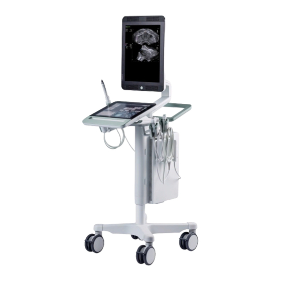
General Information bkSpecto Ultrasound System System Overview Figure 1-1 is an illustration of the bkSpecto system. bkSpecto is an assembly of multiple subassemblies: engine, wheelbase, touch monitor, monitor arm, monitor, gel holder, and transducer holders. In addition to this a variety accessories are available such as baskets, foot switch, printer start-up kit, and extra holders. -
Page 9: Scanner Serial Number
bkSpecto Ultrasound System General Information Scanner Serial Number A label similar to Figure 1-2 is located on the back of the monitor. The label contains information about Ref. type number (1), scanner specific serial number (2), model number (3), and production date (4). Figure 1-2: Scanner Specific Serial Number Label Exploded Views and Part Lists Engine... - Page 10 General Information bkSpecto Ultrasound System 10-76816-01 IO Board 10-76816-01S 21-05121-01 21-05121-01 21-05491-01 USB Cable (Charger 21-05491-01 Board J25 – IO Board USB) 21-05497-03 HDMI Cable 21-05491-01 (Charger Board J32 – IO Board HDMI) 6-81250-01 Engine Hinge Pin 6-81250-01 Standby Button Base 6-81714-01S 10-78039-01 Control Cable...
-
Page 11: Keyboard
bkSpecto Ultrasound System General Information 10-78179-01 Power Cable (Power 10-78179-01 Supply – Charger Board J24) OA0072 Mains Power Cord OA0072 Connector 111012 HDD SSD 256GB 10-80357-01S 21-05659-01 21-05659-01 10-78841-01 Battery Power Switch 10-78841-01 Assy (Power switch – Charger Board J35) Keyboard Item Reference #... -
Page 12: Top Assy
General Information bkSpecto Ultrasound System Top Assy Item Reference # Description Spare Part # Image 6-79697-01 Right cover 6-79697-01S 6-81407-01 Left cover 6-81407-01S 6-81251-01 Rear cover 6-81251-01 10-78270-01 Complete Engine 10-78270-01S with battery 10-78270-05 Complete Engine 10-78270-05S without battery 6-82832-01 Table Tray 6-82832-01 6-82717-01... -
Page 13: Monitor
bkSpecto Ultrasound System General Information Monitor Item Reference # Description Spare Part # Image Monitor Assembly 10-80462-01S Sensor and battery 10-76900-01S indicator Assembly Speaker Assembly 10-78130-01S 10-73815-01 Power Cable (Display 10-73815-01 Controller Board – LCD Panel) 21-05514-01 LVDS Cable (Display 21-05514-01 Controller Board –... -
Page 14: Internal Cabling
General Information bkSpecto Ultrasound System 6-82466-01 Transducer Base 6-82466-01 Right 6-82468-01 Transducer Base Left 6-82468-01 6-82610-01 Probe holder Frame 6-82610-01 Right 6-82609-01 Probe holder Frame 6-82609-01 Left DZ9051 Cup for holder DZ9051 6-81194-01 Probe Holder, Green 6-81194-01 6-80994-01 Gel Bottle Holder 6-80994-01 6-80995-01 Gel Bottle Holder,... - Page 15 bkSpecto Ultrasound System General Information Power Cable (Callisto Main Board – Charger 10-78129-02 10-78129-02 board) 12V Cable (Callisto Main Board – Charger 10-78038-02 10-78038-02 board) Control Cable (Callisto Main Board – Charger 10-78039-01 10-78039-01 board) LVDS Cable (Callisto Main Board – Charger 21-05514-01 21-05514-01 board)
-
Page 16: System Connectors
General Information bkSpecto Ultrasound System System Connectors The Left Side of the Engine The left side of the Control Panel Item # Symbol Description USB 3.0 (500mA current limit on each) 10/100/1000 LAN connector, RJ45 DICOM HDMI USB 2.0 (500mA current limit on each) Audio Line Out Microphone In Used for production and research purposes. -
Page 17: Troubleshooting
bkSpecto Ultrasound System General Information Troubleshooting Section four contains information about troubleshooting. Recommended tools are: USB keyboard and USB mouse. USB flash key for log files. USB flash key with software image. USB flash key with recovery tool. ... - Page 18 General Information bkSpecto Ultrasound System This page is intentionally left blank 1-14 SM41406-4...
- Page 19 bkSpecto Ultrasound System Service Notes Section 2 Service Notes CONTENTS PAGE Service Notes ............................2-2 Edition Number ............................ 2-2 SM41406-4...
- Page 20 Service Notes bkSpecto Ultrasound System Service Notes To improve system performance, small changes may occasionally be made to the system hardware and software. Information about these and other changes, as well as corrections to this Service Manual will be released as Service Hotlines and posted to the BK Ultrasound Service Web.
- Page 21 bkSpecto Ultrasound System Checking Procedure Section 3 Checking Procedure CONTENTS PAGE Checking the system after repair ......................3-2 Getting Started Guides ........................3-2 Guides ..............................3-2 Required Equipment ..........................3-2 Before Power Up..........................3-2 SM41406-4...
- Page 22 Checking Procedure bkSpecto Ultrasound System Checking the system after repair After a repair, the scanner must be tested and checked to verify if the functions operate correctly. The following situations mandate this check: during installation, incoming inspection, preventive maintenance, before and after repair. When performing a system check, all functions and controls must pass the tests described in the relevant Getting Started Guide in the User Guide.
- Page 23 bkSpecto Ultrasound System Troubleshooting Section 4 TROUBLESHOOTING CONTENTS PAGE Introduction ............................4-5 Tips for Troubleshooting Specific Problems ..................4-5 Transducer or Scanner Problem? ....................4-5 Radial or Vertical Lines ........................4-5 Noise Pattern in the B-Image ......................4-5 License-Based Function Does Not work ..................4-6 Touch Screen Display ........................
- Page 24 Troubleshooting bkSpecto Ultrasound System Replacement of SSD ........................4-23 Replacement of Engine ........................4-24 Reprogramming the Serial Number ....................4-24 Power Buttons ..........................4-26 Monitor Orientation ......................... 4-26 Access Service Mode with Bootable Device .................. 4-27 Access Control / USERS / HIPAA ....................4-27 Login in Console Mode ........................
- Page 25 bkSpecto Ultrasound System Troubleshooting Insert Certificates on Scanner ......................4-51 Create Connection Profile on Scanner................... 4-55 FAQ 802.1x ............................ 4-59 Certificate is invalid ........................4-59 Connection to a Hidden Network ....................4-60 Disk Structure / Software / Service Mode Data ................4-63 Drives and Partitions ........................
- Page 26 Troubleshooting bkSpecto Ultrasound System Batteries ............................4-81 Recharge related ..........................4-81 Collect data ..........................4-81 Read monitoring state ........................ 4-82 Read data output ........................4-82 Read Cycle count and serial number ..................4-83 Configure a Scanner to Archive to a Network Drive (SW 6.6.4 and after) ........4-83 Conforming Microsoft Windows-based PC Status .................
-
Page 27: Introduction
bkSpecto Ultrasound System Troubleshooting Introduction This section is divided into subsections, covering: specific troubleshooting issues. model-specific general functions used when servicing the system. overall test facilities in the system. Before jumping to any particular subsection first consult section 4.1 as it may supply, if not the solution, then some idea of how to troubleshoot a specific problem. -
Page 28: License-Based Function Does Not Work
Troubleshooting bkSpecto Ultrasound System Note: Before contacting the BK Ultrasound support group for help with noise problems, try the suggestions listed above. If the noise issue cannot be resolved, use the image storage facility of the scanner to save a few images that demonstrate the problem(s). -
Page 29: Basic Monitor Buttons
bkSpecto Ultrasound System Troubleshooting Basic Monitor Buttons Table 4-1 contains a description of the button functionality in the basic monitor display from Figure 4-2. Figure 4-2: View of the Basic monitor buttons on touch screen. Button Functionality Trackpad Positions the pointer, measurement calipers and labels. Pointer Displays a pointer on the monitor. -
Page 30: Accessing Setup Options
Troubleshooting bkSpecto Ultrasound System Table 4-1: Basic Monitor Buttons on the touch screen. Accessing Setup Options 1. Ensure the scanner is in Console mode 2. Select the Setup logo in the top right corner All the Setup Options are listed in Table 4-2 including the sub-options. Option Sub-Options System... -
Page 31: Time And Date Settings
bkSpecto Ultrasound System Troubleshooting Time and Date Settings. Change Time Format and Date Format 1. Tap on the Setup button. 2. Tap on SYSTEM. 3. Choose the relevant date format. 4. Choose the relevant time format. 5. Finish by UPDATE TIME/..Change Time 1. -
Page 32: Change Time Zone And Daylight Settings
Troubleshooting bkSpecto Ultrasound System Change Time Zone and Daylight Settings. 1. Ensure the scanner is in Service mode. 2. Click on the time and date in the lower right corner. 3. Click on Change date and time settings..4. Click on Change time zone..5. -
Page 33: Customize Patient Data Entries
bkSpecto Ultrasound System Troubleshooting 5. Tap on IMPORT button. 6. Select the logo and press IMPORT. Customize Patient Data Entries 1. Ensure the scanner is in Console mode. 2. Tap on the Tools button. 3. Tap on SYSTEM. 4. Go to the PATIENT DATA tab. 5. -
Page 34: Change Language
Troubleshooting bkSpecto Ultrasound System Change Language 1. Ensure the scanner is in Console mode. 2. Tap on the Tools button. 3. Tap on SYSTEM. 4. Go to the MISC tab. 5. Select the relevant language. 6. Reboot the scanner. 4-12 SM41406-4... -
Page 35: Program Foot Pedal
bkSpecto Ultrasound System Troubleshooting Program Foot Pedal 1. Ensure the scanner is in Console mode and logged in as an administrator. 2. Tap on the Tools button. 3. Click on SYSTEM. 4. Go to the MISC tab. 5. Select the relevant foot pedal and function on the list. Video Output 1. -
Page 36: Changing Measurement Results
Troubleshooting bkSpecto Ultrasound System Option Definition Default. Video Outputs are disabled. Select to enable them. HDMI output (1024 x 768) Passive Enables a large image on the external monitor, but the output is not identical Display to the scanner monitor (although the ultrasound image is identical). HDMI output (1280x1024) Cloned Enables a large image on the external monitor identical to the image on the... -
Page 37: Changing Labels
bkSpecto Ultrasound System Troubleshooting b. A table with available calculations is now shown. c. Select the relevant calculation and press Add. 7. To remove calculations. a. Select the button, which should be remove. b. Select Remove. Changing Labels 1. Tap on the Tools button. 2. -
Page 38: Configure Layout For The Parameter Buttons
Troubleshooting bkSpecto Ultrasound System 7. To remove labels: a. Select the label which should be removed. b. Tap on the Remove button Configure Layout for the Parameter Buttons. The touch functionality allows to customize the user layout. 5 & 6 Figure 4-3: Drag buttons to the parameter button display. -
Page 39: Access The User Guide
bkSpecto Ultrasound System Troubleshooting 2. Tap on Configuration Layout. 3. Select relevant Pro package from the drop-down menu. 4. Select the relevant mode 2D, Color, PW etc.. 5. To add buttons on the Parameter button area. Drag the buttons from the lower left corner to the plusses as shown in Figure 4-3. - Page 40 Troubleshooting bkSpecto Ultrasound System Module Name Host name Free HDD space Scanner Variant Engine software version Console software version Flexiblekeyboard software version XPE version License ID (00 00 0 followed by scanner SN) MAC Address Hardware Capabilities Firmware versions. Table 4-4: Service related information in the about tab. 4-18 SM41406-4...
-
Page 41: Error Dialogs In Console Mode
bkSpecto Ultrasound System Troubleshooting Error Dialogs in Console Mode If an error is detected by the Console and classified as Fatal then an Error dialog will appear on the touch display. Fatal means the error can affect the scanner performance why the scanner must be fixed before it can be used for scanning again. -
Page 42: Service Mode And Console Mode
Troubleshooting bkSpecto Ultrasound System Service Mode and Console mode The scanner can be in one of two modes: Console mode and Service mode. Console mode is the main mode which is used for clinical purposes where Service mode can be accessed by BK Ultrasound certified technicians. -
Page 43: Entering Service Mode (With Usb Keyboard)
bkSpecto Ultrasound System Troubleshooting Entering Service Mode (with USB keyboard) 8. Turn on the scanner and wait until the boot cycle is complete and opens in Console mode. 9. Press ALT + X. 10. Type in the Service Mode Password, chapter 4.28. 11. -
Page 44: Shutting Down The Scanner From Service Mode
Troubleshooting bkSpecto Ultrasound System Shutting Down the Scanner from Service mode 1. On the Service Desktop, double-click the Shutdown Scanner icon. CAUTION: Turning on the scanner again and it will start in Service mode. Note: If this does not work. Press the power button on the engine once and wait 60 seconds. Then the scanner will shut down. -
Page 45: Repair Using Spare Parts
bkSpecto Ultrasound System Troubleshooting Repair using Spare Parts With a few exceptions, which are listed in Table 4-7, all boards and modules which are available as spare parts can be replaced with no additional tasks. Before replacing a subassembly verify item number and revision of the new part are compatible with the item number of the defective part. -
Page 46: Replacement Of Engine
Troubleshooting bkSpecto Ultrasound System Replacement of Engine 1. Follow the steps in section 6 Mechanical Parts for changing the engine. 2. Disable encryption, ref. 4.40.3.2. 3. Reprogram the serial number, ref. 4.23. 4. Import the user settings if available, ref. 4.47.2. 5. - Page 47 bkSpecto Ultrasound System Troubleshooting 9. From the Board Selection drop-down menu select Callisto Main Board. 10. If the Additional Data field already contains a number, write it down in the event of a rollback is necessary. 11. In the Additional Data field, enter the code obtained from BK Ultrasound and press Write.
-
Page 48: Power Buttons
Troubleshooting bkSpecto Ultrasound System 14. Double-click on the service desktop icon Start Console. 15. Follow 4.15 and to ensure the system serial number is correct. 16. Ensure the Licenses are submitted and valid, ref. 4.46. 17. Exit the Console application. 18. -
Page 49: Access Service Mode With Bootable Device
bkSpecto Ultrasound System Troubleshooting Access Service Mode with Bootable Device If it is not possible to access Service mode the tool Restore to Service Mode is available on the BK Ultrasound Service Web. Access Control / USERS / HIPAA Login in Console Mode 1. -
Page 50: User Profiles
Troubleshooting bkSpecto Ultrasound System 3. Select Logout User profiles From default the scanner has two profiles: Default Sys Admin and Default User. The passwords are available in chapter 4.28. It is possible to create additional users and administrator with customizable settings and preferences. Add a User 1. -
Page 51: Remove A User
bkSpecto Ultrasound System Troubleshooting 6. Submit the personal information, and tap on Next 7. Create a password and tap on Add 8. Follow to 4.27.3.3 to customize the user settings and preferences. Remove a User 1. Ensure the scanner is in Console mode and logged in as an administrator. 2. - Page 52 Troubleshooting bkSpecto Ultrasound System 5. Tap on VIEW PROFILE. 6. A variety of user specific general settings and preferences are available, ref. Table 4-9 and Table 4-10. General User Settings (A) Add user photo. (B) Change Password. (C) Profile type. (D) Password mandatory.
-
Page 53: Passwords
bkSpecto Ultrasound System Troubleshooting Passwords The scanner has default passwords. From software version 6.64 the passwords are no longer hardcoded but can be changed. Feature Shortcut Password (SW 6.62) Password (6.64 and higher) Configure Network Admin password OEM interface Ctrl + shift + O Admin password Service Mode Alt + X... -
Page 54: Setting Up The Dicom Host
Troubleshooting bkSpecto Ultrasound System 3. Tap on CONFIGURE DICOM/PACS 4. The DICOM Setting Dialog appears on the monitor. Setting up the DICOM Host 1. Access the DICOM Setting Dialog according to 4.29.1. 2. Enter the AE Title for the scanner. 3. -
Page 55: Worklist Setup
bkSpecto Ultrasound System Troubleshooting 10. Select Properties. 11. To use a fixed IP address, select Use the following IP address and fill out the required fields with the data provided by the institution: IP address Subnet mask Default gateway. 12. - Page 56 Troubleshooting bkSpecto Ultrasound System Search Filter Values Definition This System Only The AE title of the scanner will then be used to differentiate. Ultrasound System Only (0008,0060)-tag must be ultrasound (US) in the record in the worklist. All Systems No filtering. All modalities on the worklist will appear on the scanner.
-
Page 57: Pacs Setup
bkSpecto Ultrasound System Troubleshooting 6. Is the connection not a success make sure the information from the DICOM Network Description questionnaire has been added correctly. 7. Select OK twice. PACS Setup Note: Scanner AE Title must be present before testing can be done. Setting up PACS includes choosing parameters for Archiving Method, Auto Send Timeout, and Storage Commitment. - Page 58 Troubleshooting bkSpecto Ultrasound System To Configure PACS Server: 1. Access the DICOM Setting Dialog according to 4.29.1. 2. Select Add (next to PACS field). 3. Enter Name, AE Title, IP Address and Port Number. Note: Once accepted, Name cannot be edited. 4.
-
Page 59: Dicom Printers Setup
bkSpecto Ultrasound System Troubleshooting 7. Configure the Storage Commitment options: Name, AE Title, Host Name or IP Address, and Port Number Note: Once accepted, Name cannot be edited. 8. Select Test. 9. Select OK twice. DICOM Printers Setup Note: Scanner AE Title must be present before testing can be done. To Configure Printers: 1. -
Page 60: Dicom Troubleshooting
Troubleshooting bkSpecto Ultrasound System Note: Once accepted, Name cannot be edited. 4. From the Default Printer drop-down menu, select the desired setting. Note: Each time a new printer is added, it will automatically become the default. Select from the following options: ... -
Page 61: Dicom Status
bkSpecto Ultrasound System Troubleshooting If AE Title is set and the DICOM echo still fails, you may get a message like this Check the following items to ensure they are correctly configured and/or connected: Scanner target host AE Title and Port Number. - Page 62 Troubleshooting bkSpecto Ultrasound System 3. The DICOM Status dialog will be presented. To Delete Documents in the DICOM Queue: 1. Access the DICOM Setting Dialog according to 4.29.1. 2. Select Status. 3. The DICOM Status dialog will be presented. 4-40 SM41406-4...
- Page 63 bkSpecto Ultrasound System Troubleshooting 4. To stop any additional send attempts, select a document from the Document List and select Cancel to delete it. Note: Selecting Cancel All will clear the entire list. 5. Select Yes to confirm the deletion or No to cancel it. To Test (Failed) DICOM Server/Printer: 1.
-
Page 64: Ping
Troubleshooting bkSpecto Ultrasound System 3. The DICOM Status dialog will be presented. 4. Select a server/printer (with a LED) from the Device List and select Details. Ping To Ping a DICOM Server: 1. Access the DICOM Setting Dialog according to 4.29.1. 2. -
Page 65: Printers
bkSpecto Ultrasound System Troubleshooting Printers Two kinds of printers are available: Sony black and white integrated printer and office printers. Setting Up a Sony Printer Setting Up an Office Printer This is covered in the User Guide available on the BK Ultrasound webpage. Crash Recoveries Log Files Log files and a fault description are often necessary for remote support by your BK... -
Page 66: How To Read Log Files
Troubleshooting bkSpecto Ultrasound System 8. Wait for the files to be transferred. How to Read Log Files The log file contains a variety of relevant files for troubleshooting. Table 4-16 is an overview of the most basic files in the log file. File Name Purpose Viking.ini... -
Page 67: Find Scanner Ip Address In Service Mode
bkSpecto Ultrasound System Troubleshooting 5. The IP address is available on the list. Find Scanner IP Address in Service Mode 1. Ensure the scanner is in Service Mode. 2. Go to the home screen by pressing CTRL + ESC. 3. Write cmd. 4. - Page 68 Troubleshooting bkSpecto Ultrasound System 6. Select Advanced Wi-Fi Setup. 7. Submit the password, ref. chapter 4.28 8. Double-click on Wi-Fi or Ethernet. 9. If Wi-Fi was chosen press Properties. If Ethernet was chosen continue to next step. 10. Select Internet Protocol Version 4 (TCP/IPv4). 11.
-
Page 69: Ping/Echo Requesty Functionality
bkSpecto Ultrasound System Troubleshooting 12. To use a fixed IP address, select Use the following IP address and fill out the required fields with the data provided by the institution: IP address Subnet mask Default gateway. 13. Select OK until all windows are closed. 14. - Page 70 Troubleshooting bkSpecto Ultrasound System 9. Search for “Windows Firewall”. 10. Enter advanced settings. 11. Enter Inbound Rules 12. Find the “File and Printer Sharing (Echo Request – ICMPv4-In)” rule in the “Inbound Rules” list. 13. Right click on the “File and Printer Sharing (Echo Request – ICMPv4-In)” and select Enable rule 14.
-
Page 71: Configuring Wi-Fi
bkSpecto Ultrasound System Troubleshooting Configuring Wi-Fi Setting up Wi-Fi in Console mode (basic). 1. Ensure the scanner is in Console mode. 2. Tap on Tools button. 3. Tap on STORE / NETWORK. 4. Tap on the Wi-Fi tab. 5. Tap on CONFIGURE Wi-Fi. 6. -
Page 72: Disable Wi-Fi, Bluetooth, And Network Connection
Troubleshooting bkSpecto Ultrasound System 2. Click on the Wi-Fi symbol. 3. Change Wi-Fi to off. Disable Wi-Fi, Bluetooth, and Network Connection 4. Ensure the scanner is in Service mode. 5. Click on the Wi-Fi symbol or the network symbol. 6. Change Airplanu mode to On. 802.1x settings It is possible to setup Wi-Fi security using 802.1x authentication. -
Page 73: Preparations
bkSpecto Ultrasound System Troubleshooting Preparations To use enterprise authentication (802.1x) the local IT department must issue the following: Password protected certificate with personal key for “Personal” as a .PFX file (including the password). Root certificate from issuing certificate servers for “Trusted Root Certification Authorities”. - Page 74 Troubleshooting bkSpecto Ultrasound System 4. Press “Add”. 5. Select “Computer account” and press ”Next”. 6. Press ”Finish” 4-52 SM41406-4...
- Page 75 bkSpecto Ultrasound System Troubleshooting 7. ”Certificates (Local Computer)” is now added to the snap-ins. Press “OK”. 8. Open ”Certificate (Local Computer)”. 9. Right-click “Personal”. Select “All Tasks” --> “Import” from the options. 10. Use the “Certificate Import Wizard” to select the .PFX certificate file with private key obtained from the local IT department for “Personal”.
- Page 76 Troubleshooting bkSpecto Ultrasound System 11. Right click on “Trusted Root Certification Authorities”. Select ”All Tasks” --> ”Import...”. 12. Use the “Certificate Import Wizard” to select the certificate file obtained from the local IT department for “Trusted Root Certification Authorities”. Follow the import guide. 13.
-
Page 77: Create Connection Profile On Scanner
bkSpecto Ultrasound System Troubleshooting 15. Ensure the root servers in the path are trusted. Two possibilities: The certificate is not issued by a trusted The certificate is issued by a trusted source. Go to 0 Error! Reference source. Continue this guide. source not found.”. - Page 78 Troubleshooting bkSpecto Ultrasound System 19. Select “Set up a new connection or network”. 20. Select Manually connect to a wireless network. Press Next. 21. Enter the SSID (network name) of the wireless network and select WPA2-Enterprise security. 22. Choose Start this connection automatically and click Next. 4-56 SM41406-4...
- Page 79 bkSpecto Ultrasound System Troubleshooting 23. Click on Change connection settings. 24. Select the Security tab and choose Microsoft: Smart Card or other Certificate as authentication method. 25. Click Settings. 26. Ensure Verify the server’s identity by validating the certificate is enabled. 10.
- Page 80 Troubleshooting bkSpecto Ultrasound System 11. Click on Advanced settings. 12. Select Specify authentication mode: and choose Computer authentication from the dropdown menu. 13. Click OK and Click OK again on the next screen. 14. Press the Wireless icon on the taskbar. 15.
-
Page 81: Faq 802.1X
bkSpecto Ultrasound System Troubleshooting FAQ 802.1x Certificate is invalid 1. Open the Certification Path tab. 2. If a red circle with a white cross is present this source is not trusted. 3. The identity certificate for the source must be obtained from the IT department and imported to Trusted Root Certification Authorities as described in the previous procedure. -
Page 82: Connection To A Hidden Network
Troubleshooting bkSpecto Ultrasound System Connection to a Hidden Network 1. Ensure that the system is in service mode. 2. Plug in a USB keyboard. 3. Select the Windows button on the keyboard, and search for cmd. 4. Right click on the button and select run as administrator. 5. - Page 83 bkSpecto Ultrasound System Troubleshooting 9. Select Network and Sharing Center. 10. Select Set up a new connection or network. 11. Select Manually connect to a wireless network. SM41406-4 4-61...
- Page 84 Troubleshooting bkSpecto Ultrasound System 12. Complete the form with all relevant details. 13. Select Next 14. When presented with successful installation window, select Close. 15. On the Service Desktop, double-click on the desktop icon Console Mode. 16. Type Y and press Enter to exit Service Mode. 4-62 SM41406-4...
-
Page 85: Disk Structure / Software / Service Mode Data
bkSpecto Ultrasound System Troubleshooting Disk Structure / Software / Service Mode Data This section covers directory structure and some of the more important system files. Drives and Partitions The scanner comes with one SSD drive containing three partitions. Using Disk Management in Service mode will allow the user to get an overview of the disk and partitions, Figure 4-5. -
Page 86: C:\ Drive - Service Relevant Content
Troubleshooting bkSpecto Ultrasound System C:\ Drive – Service Relevant content Directories and files standard to Microsoft Windows will not be addressed here. Table 4-18 is an overview of service relevant content on the C drive. Path Relevant files & Content Directories lbk.bin Scanner licenses file. -
Page 87: Bodymarks
bkSpecto Ultrasound System Troubleshooting Figure 4-6: C:\ root content Bodymarks Each bodymark has a separate image file. The default file naming policy is bodym_<number>.bmp (fx. Bodym_001.bmp). Any bodymark image file which does not follow this naming policy is custom made. If a system recovery is required, make a copy of the custom files for safe keeping. -
Page 88: Findusbdisplay-Callisto.cmd
Troubleshooting bkSpecto Ultrasound System Level name Log level Description LOG_LEVEL_NONE Do not write log messages of any level. LOG_LEVEL_FATAL Log fatal errors. LOG_LEVEL_ERROR Log errors and fatal errors. LOG_LEVEL_WARNING Log warning, errors and fatal errors. (Default) LOG_LEVEL_INFO Log information messages, warnings, errors, and fatal errors LOG_LEVEL_DEBUG Log debug messages, information... -
Page 89: Q:\ Drive
bkSpecto Ultrasound System Troubleshooting 20. Press the touch screen if it looks like below. If not press enter to exit the tool. 21. Choose display 1 as Display and make sure Details is Limited Touch Support. 22. Press OK. Q:\ Drive Q:\ is used to save patient data in the Documentation folder. -
Page 90: Disable Hardware Encryption Of Q Drive
Troubleshooting bkSpecto Ultrasound System 5. Check the padlock on the Q drive in File Explorer 6. If you see it, then select the prompt and click on any key for the window to disappear. Disable Hardware Encryption of Q Drive 1. -
Page 91: Run Chkdsk
bkSpecto Ultrasound System Troubleshooting Run ChkDsk 1. Open Windows Explorer. 2. Right click on C:\ and select Properties. 3. Select the Tools tab and select Check. 4. Select the Scan Drive to continue or Cancel to close the message without completing the scan. -
Page 92: Rd Part Software On The Scanner
Troubleshooting bkSpecto Ultrasound System 7. Details are shown in Event Viewer. Double click the Information event. 8. The status of the check is described in the report. 9. Select Close to exit, close EventViewer, and press Close to exit the check disk tool. Part Software on the Scanner Do not install any 3 part software on the scanner. -
Page 93: Installing New Software
bkSpecto Ultrasound System Troubleshooting Installing New Software Always follow the installation guide provided with the specific software image version. Activate Windows If the messages in Table 4-20 appear in the bottom right corner of the monitor Windows has not been activated. Service Mode Console Mode Table 4-20: Activate Windows is shown on the monitor in Service mode and Console... - Page 94 Troubleshooting bkSpecto Ultrasound System 6. Finish procedure online or by call Microsoft. 4-72 SM41406-4...
-
Page 95: Bios
bkSpecto Ultrasound System Troubleshooting BIOS Accessing BIOS is possible when booting the scanner. 1. Insert a USB Keyboard. 2. Press the power button on the scanner. 3. Press Esc on the keyboard. 4. Submit the BIOS password, chapter 4.28 5. Press enter. Reset BIOS to Default 1. -
Page 96: Save Bios Changes
Troubleshooting bkSpecto Ultrasound System Save BIOS Changes 1. Access BIOS following 4.45.1. 2. Perform the relevant changes. Changes should only be done according to official instruction by BK Ultrasound. 3. Go to Save & Exit. 4. Choose Save Changes and Exit. Update BIOS BIOS updates will be made available on the official BK Ultrasound Service Web including installation procedure. -
Page 97: License Keys / Pro Packages / Calc. Packages (Demo License Keys)
bkSpecto Ultrasound System Troubleshooting License Keys / Pro Packages / Calc. Packages (Demo License Keys) Software licenses in combination with the unique Scanner ID enable the options and features available on each system. This ensures that any given license only will work on a specific scanner. -
Page 98: Reinstalling Licenses From A File
Troubleshooting bkSpecto Ultrasound System 5. Tap on Apply. 6. Restart the system. 7. Verify the new license is installed correctly. Reinstalling Licenses from a File 1. Insert the USB flash key containing the license (as a .lic file) into a USB input. 2. -
Page 99: Delete Licenses
bkSpecto Ultrasound System Troubleshooting 6. Select the desired License key and select IMPORT LICENSES. 7. Once the file has been successfully imported, restart the system. 8. Verify the new licenses are installed correctly. Delete Licenses 1. Enter Service mode. 2. Navigate to Windows (C:) in Windows Explorer. 3. -
Page 100: Demo Licenses
Troubleshooting bkSpecto Ultrasound System Demo Licenses Tables below contain information about the demo license keys including the part numbers you can buy. Optional Feature Part number Demo License key(s) bkSpecto Built in 0000-0000-0000-0242 3D Professional Expired in SW 6.6.4 0000-0000-0000-0000 3D Freehand UA2471 0000-0000-0000-0015... -
Page 101: Transferring Data To A New 1300
bkSpecto Ultrasound System Troubleshooting Transferring Data to a New 1300 Export Presets, User Profiles, or System Settings. 1. Insert USB flash key. 2. Tap on Tools button. 3. Tap on SERVICE. 4. Tap on the relevant export feature. Import Presets, User Profiles, or System Settings. 1. -
Page 102: Export A Specific Preset
Troubleshooting bkSpecto Ultrasound System Note: If the import fails make sure you are logged in as an administrator. Export a Specific Preset. 1. Insert USB flash key. 2. Tap on Tools button. 3. Tap on PRESETS. 4. Tap on MANAGE. 5. -
Page 103: Batteries
bkSpecto Ultrasound System Troubleshooting 6. Select the preset on the list. 7. If the preset already exists you have to Overwrite existing preset. If the preset does not exist continue with Overwrite existing preset disabled. 8. Tap on IMPORT. Batteries If you have a battery-system (1300-25), you can use following chapter to evaluate the status of the 2 batteries. -
Page 104: Read Monitoring State
Troubleshooting bkSpecto Ultrasound System 2. Doubleclick on Terminal icon on the desktop 3. Make sure all settings are as depicted below. The COM Port can be different 4. Click on Connect Button 5. Type mon 9; 6. click on Send Data output area 7. -
Page 105: Read Cycle Count And Serial Number
bkSpecto Ultrasound System Troubleshooting Full electrical charge measure in To extend the battery life, we never charge the batteries to full electrical charge, so rc wil never be equal to fc Default value is approx. 3800 mAh Measured voltage in mV Default value is approx. - Page 106 Troubleshooting bkSpecto Ultrasound System 1. Press the [Windows start key] + [x] and select Control Panel. 2. Select System. 3. Select Change Settings. 4. In the System Properties dialog select the Computer Name tab. 4-84 SM41406-4...
- Page 107 bkSpecto Ultrasound System Troubleshooting 5. Make a note of the Full computer name and Domain (in this example b1016.bkmed.dk and analogic.com). NOTE: IF the computer is a member of a Workgroup rather than a Domain then Domain will be replaced by Workgroup. Configure Microsoft Windows-based PC NOTE: This is not to be done on the scanner.
- Page 108 Troubleshooting bkSpecto Ultrasound System 5. Select Advanced Sharing…. 6. Check Share this folder. 7. Type in a Share name (in this example bkSpectoData). 8. Select Permissions. bkSpectoDataUser 4-86 SM41406-4...
-
Page 109: Configure Network
bkSpecto Ultrasound System Troubleshooting 9. Select the Allow checkbox next to Change. 10. Select OK twice. 11. Select Close to exit. Configure Network NOTE: This is not to be done on the scanner. The scope of this document does not include network configuration. It’s important to note however that the network should be configured before configuring the scanner’s network settings which is the next step (4.49.4). -
Page 110: Troubleshooting
Troubleshooting bkSpecto Ultrasound System Text Details Connection succeded Success No server path was specified Server field is empty. Type in the missing data (step 4) The login credentials could not be saved Username field is empty. Type in the missing data (step The specified server name is invalid or Verify Server field and check network connection could not be located... - Page 111 bkSpecto Ultrasound System Troubleshooting SM41406-4 4-89...
- Page 112 bkSpecto Ultrasound System Adjustment Procedure Section 5 Adjustment Procedure CONTENTS PAGE Introduction ............................5-2 Touchscreen Brightness ........................5-2 Display Brightness ..........................5-3 SM41406-4...
- Page 113 Adjustment Procedure bkSpecto Ultrasound System Introduction All adjustable components are managed in the factory and need no further handling in the field. With the exception of the items detailed below, do not attempt any other adjustments. Touchscreen Brightness Before adjusting the brightness, make sure you match the ambient environment used by the operator.
- Page 114 bkSpecto Ultrasound System Adjustment Procedure Display Brightness Before adjusting the brightness, make sure you match the environment used by the operator. Note: Brightness setting of the touch screen is a user preference setting. 1. Tap on the Tools button. 2. Tap on the Display button. 3.
- Page 115 Adjustment Procedure bkSpecto Ultrasound System This page is intentionally left blank SM41406-4...
- Page 116 bkSpecto Ultrasound System Mechanical Parts Section 6 Mechanical Parts CONTENTS PAGE Introduction ............................6-2 Screw Overview ........................... 6-2 Engine ..............................6-3 Remove the Engine from Wheelbase ....................6-4 Remove the Left Chassis ......................... 6-8 Remove Battery Assembly ....................... 6-9 Remove IO – Board ........................6-11 Remove the Power Supply ......................
-
Page 117: Introduction
Mechanical Parts bkSpecto Ultrasound System Introduction This section describes how to disassembly the scanner step by step. bkSpecto is divided into four main mechanical parts: Engine Monitor Top Assembly Wheelbase Caution: Turn off the scanner before replacing mechanical parts and lock the wheels. Screw Overview All screws used in this section are described with part number and size in Table 6-1. -
Page 118: Engine
bkSpecto Ultrasound System Mechanical Parts Engine The engine is divided into two parts separated by the main mounting plate. To access parts under the main mounting plate it is not necessary to remove all the parts on the plate. By removing the main mounting plate, one gets access to the parts below. -
Page 119: Remove The Engine From Wheelbase
Mechanical Parts bkSpecto Ultrasound System Remove the Engine from Wheelbase Procedure: Caution: Turn off the standby power on the power switch below the engine. Scanner overview Parts Main power Switch 1. Remove the basket and other accessories on the engine. SM41406-4... - Page 120 bkSpecto Ultrasound System Mechanical Parts 2. Remove 9 screw covers on the engine to get access to the screws. Place a plastic tool or a The screw cover has two pins as locking mechanisms screw driver in the pocket, which fits into the engine cover. press upwards, and pull.
- Page 121 Mechanical Parts bkSpecto Ultrasound System 4. Remove the two screws from the back and remove the back cover. M4X10 5. Remove three screws holding the engine in the order as shown on the picture. Caution: It is important to support the engine at the bottom when removing the screws. M4X30 M5X12 M5X12...
- Page 122 bkSpecto Ultrasound System Mechanical Parts 6. Remove the six cables from the engine. Note: It is important to remember the order in which the cables are attached Power Printer Power Monitor Power Keyboard USB Keyboard LVDS Keyboard HDMI Monitor 7. Push the engine back in place and it is possible to remove the engine by lifting it of the wheelbase.
-
Page 123: Remove The Left Chassis
Mechanical Parts bkSpecto Ultrasound System Remove the Left Chassis Initial tasks in chronological order: 6.2.1 Remove the Engine from Wheelbase Procedure: Caution: Place the engine with the locking handles next to the table making sure the probe locking handles are not being squished by the weight of the engine. 1. -
Page 124: Remove Battery Assembly
bkSpecto Ultrasound System Mechanical Parts 3. Unfasten the 8 screws and remove the chassis. M4X1 M3X6 Note: Remember to insert the power button extender when assembling the scanner again. Remove Battery Assembly Initial tasks in chronical order: 6.2.2 Remove the Left Chassis Procedure: 1. - Page 125 Mechanical Parts bkSpecto Ultrasound System # Fan Fan Location Below CMB Below CMB Below CMB Chager Board Mounting Plate (center fan) Mounting Plate Table 6-3: Fan Locations. 3. Gently loosen the metal brackets and remove the wires. CAUTION: Caution not to cut the cables on the metal bracket locks. 4.
-
Page 126: Remove Io - Board
bkSpecto Ultrasound System Mechanical Parts 6. Remove the four nuts with a 7mm socket wrench. NUT M4 7. It is now possible to remove the battery assembly. Remove IO – Board Initial tasks in chronical order: 6.2.2 Remove the Left Chassis Procedure: M3X12 USB 3.0... -
Page 127: Remove The Power Supply
Mechanical Parts bkSpecto Ultrasound System 3. Gently remove the IO-board from the callisto main board. The connector area is indicated on the image. Remove the Power Supply Initial tasks in chronological order: 6.2.3 Remove Battery Assembly Procedure: Caution: Two different power supplies are available for bkSpecto. Be aware that the wires are connected opposite on the different models. -
Page 128: Remove Charger Board Assembly
bkSpecto Ultrasound System Mechanical Parts 2. Remove the red, blue, and green wire from the power supply. Power supply cable ground cable. M3X6 3. Remove the four screws. 4. It is now possible to remove the power supply. Remove Charger Board Assembly Initial Tasks in chronological order: 6.2.2 Remove the Left Chassis... - Page 129 Mechanical Parts bkSpecto Ultrasound System 2. Remove the LVDS cable on the CMB. 3. Pull the connector to remove the red wire to the on/off button gently. Caution: Use a pair of tweezers to get a good grip on the connector. Do not pull at the wires. 4.
-
Page 130: Remove The Main Mounting Plate
bkSpecto Ultrasound System Mechanical Parts 5. Remove the seven screws M3X6 M3X20 6. It is now possible to remove the charger board assembly. Remove the Main Mounting Plate Initial tasks in chronological order: 6.2.4 Remove IO – Board 6.2.6 Remove Charger Board Assembly Procedure: 1. - Page 131 Mechanical Parts bkSpecto Ultrasound System 3. Remove the LVDS cable on the CMB. 4. Remove three nuts from the GPU case and remove the case. 5. Remove one screw from the GPU. M3X6 6-16 SM41406-4...
- Page 132 bkSpecto Ultrasound System Mechanical Parts 6. Remove the three wires from the power supply. 7. Remove the seven screws on the engine chassis. M3X5 SM41406-4 6-17...
- Page 133 Mechanical Parts bkSpecto Ultrasound System 8. Remove 12 screws from the main mounting plate. M3X6 9. Remove the main mounting plate. Note: When assembling the scanner remember to position the zip ties for fixating the cables above the mounting plate. 6-18 SM41406-4...
-
Page 134: Remove The Hard Disk
bkSpecto Ultrasound System Mechanical Parts Remove the hard disk Initial tasks in chronological order: 6.2.7 Remove the Main Mounting Plate Procedure: 1. Remove the screw 2. Gently lift and slide off the hard disk. SM41406-4 6-19... -
Page 135: Remove The Gpu
Mechanical Parts bkSpecto Ultrasound System Remove the GPU Initial tasks in chronological order: 6.2.7 Remove the Main Mounting Plate Proceduce: 1. Remove the two screws. M3X6 2. Gently lift and slide off the GPU. Remove the On/Off Button Initial tasks in chronological order: 6.2.7 Remove the Main Mounting Plate Procedure: 1. -
Page 136: Remove The Bios Battery
bkSpecto Ultrasound System Mechanical Parts Remove the BIOS battery Initial tasks in chronological order: 6.2.2 Remove the Left Chassis Procedure: 1. Remove the USB connector on the IO board. 2. Gently remove the BIOS Battery. SM41406-4 6-21... -
Page 137: Top Assembly
Mechanical Parts bkSpecto Ultrasound System Top Assembly Remove Flex Keyboard 1. Remove the four screws on the keyboard enclosure. Note: It is not necessary to remove the green handle on the front. M4X128 2. Lift the keyboard but watch out for the wires and cables. 3. -
Page 138: Monitor
bkSpecto Ultrasound System Mechanical Parts 4. Disconnect all cables. Touch Power Overlay Monitor Speaker Printer LVDS Engine SM41406-4 6-23... -
Page 139: Remove Monitor Assembly
Mechanical Parts bkSpecto Ultrasound System Monitor Remove Monitor Assembly 1. Remove the four cover plugs (6-83622-01) using a thin flat screw driver. The gap in the cover plug must face towards the center of the back cover of the monitor when the scanner is being assembled. - Page 140 bkSpecto Ultrasound System Mechanical Parts 4. Cut off the zip tie Caution: Do not pull at the wires but use the connectors for a firm grip. 5. Remove the four Speaker wires. 6. Remove the video Video connector. Connector 7. Remove the power connector.
-
Page 141: Remove Speaker Assembly
Mechanical Parts bkSpecto Ultrasound System Remove Speaker Assembly The monitor contains two speaker assemblies. It is in this guide shown how to remove the right speaker assembly. The gap in the cover plug must face towards the center of the back cover of the monitor when the scanner is being assembled. - Page 142 bkSpecto Ultrasound System Mechanical Parts 3. Remove the two speaker wires. 4. Remove 11 M3X8 screws. SM41406-4 6-27...
- Page 143 Mechanical Parts bkSpecto Ultrasound System 5. Gently lift and slide out the Speaker Assembly. 6-28 SM41406-4...
-
Page 144: Wheelbase
bkSpecto Ultrasound System Mechanical Parts Wheelbase Remove Transducer Holders and Gel Holders The scanner comes with two transducer holders on the right side and one gel holder and one transducer holder on the left side. Transducer Gel Holder Holder Bottle Elastomer holder insert... - Page 145 Mechanical Parts bkSpecto Ultrasound System Part number Parts 6-80994-01 Gel Holder Gel Holder 6-83704-01 (Elastomer insert) DZ9051 Transducer Holder Transducer Holder 6-83704-01 (Elastomer insert) Table 6-4: Transducer overview Note: Each side has opposite construction, and in this guide it is shown how to remove the right side. By default the system comes with two holders on each side but two more holders can be added.
-
Page 146: Remove The Probe Holder Frame
bkSpecto Ultrasound System Mechanical Parts Note: Each holder is attached with two small rods of metal on the stiffener. Remove the Probe Holder Frame 1. Remove the two screws. CAUTION: Remember to support the probe holder frame, while removing the screws. 2. -
Page 147: Remove Handrail
Mechanical Parts bkSpecto Ultrasound System Remove Handrail 1. Remove the two screws under the Handrail. M6X30 2. Gently slide off the handrail from the metal attached to the wheelbase. 6-32 SM41406-4... -
Page 148: Remove The Protective Caps (6-83026-01)
bkSpecto Ultrasound System Mechanical Parts Remove the Protective Caps (6-83026-01) 1. Use a screw driver to unlock the cap. 2. The cap can be removed by sliding it of the wheelbase. SM41406-4 6-33... - Page 149 Mechanical Parts bkSpecto Ultrasound System This page is intentionally left blank 6-34 SM41406-4...
- Page 150 bkSpecto Ultrasound System Preventative Maintenance Section 7 Preventative Maintenance CONTENTS PAGE Introduction ............................7-2 Required Equipment ..........................7-2 Parts Required to Ensure System Performance and Stability ............7-2 Parts Required to Respond to Customer Requests and/or Complaints .......... 7-2 Standard Tools and Equipment Required to Perform the PM ............7-2 Performing a PM ..........................
- Page 151 Preventative Maintenance bkSpecto Ultrasound System Introduction The purpose of preventative maintenance (PM) is to ensure performance and stability over the lifetime of a system. Note: A PM should be performed once a year. Preparing for a PM visit is essential as in most cases it is completed as a part of an institution’s Continuity Agreement.
- Page 152 bkSpecto Ultrasound System Preventative Maintenance Note: Various malfunctions can be corrected by making setup adjustments! Correct any obvious errors at this stage. Modifications In accordance with the relevant Service Information bulletins posted on the BK Ultrasound Service Web, perform the necessary hardware/software modifications/updates to ensure outstanding system performance and stability.
- Page 153 Preventative Maintenance bkSpecto Ultrasound System Peripherals The tests in Table 7-1 verify correct peripheral functionality. Peripheral Procedure Transducers Leakage test according to ”Care and Cleaning guide” (BB1564). Electrical safety test, applied leakage current. Printer Capture an ultrasound image and print it. If necessary, adjust the printer using the original instruction manual.
- Page 154 bkSpecto Ultrasound System Theory of Operation Section 8 Theory of Operation CONTENTS PAGE Introduction ............................8-2 General Description ..........................8-2 Block Diagram ............................8-2 Board Description ..........................8-3 Glass UI Control Panel ........................8-3 Scan Engine Module ........................8-4 Power Supply Module ........................8-10 Display Module ..........................
-
Page 155: Introduction
Theory of Operation bkSpecto Ultrasound System Introduction This section describes the theory of operation of the scanner. The description is divided into two separate sub-sections, each: General Description: Supported by a block diagram, this section aims to give you an understanding of the interaction between modules, boards, and major function blocks in the system. - Page 156 bkSpecto Ultrasound System Theory of Operation Board Description Glass UI Control Panel The Glass UI Control Panel represents the input part of the User Interface, allowing the user to control the system. Figure 8-1 is a block diagram of the glass UI control panel. 2 x USB Speaker Conn...
-
Page 157: Scan Engine Module
Theory of Operation bkSpecto Ultrasound System Scan Engine Module The engine contains both the ultrasound generating equipment, the computer, processing power, power supply, data storage etc. Figure 8-2 is a block diagram of the main parts in the engine. Speaker Speaker Speaker Speaker... - Page 158 bkSpecto Ultrasound System Theory of Operation The front-end part is responsible for providing the physical interface to ultrasound transducers, generating high-voltage pulses to excite the transducer ceramics, and amplifying and acquiring the low-voltage echoes from the transducers. Figure 8-3 is an overview of the main block on the front end.
- Page 159 Theory of Operation bkSpecto Ultrasound System Adding the digital channels from the Receiver Function in phase to focus in a specific direction. The phase alignment is dynamic and time-variant; as the emitted sound field propagates away from the transducer, it is reflected from scatters of increasing depth. Therefore, the focal point of the receiver must track the emitted field.
- Page 160 bkSpecto Ultrasound System Theory of Operation 8.3.2.1.2 CMB Back-end Part Figure 8-4: Block diagram of CMB back end. Figure 8-4 is an overview of the main blocks on the CMB back end. The back-end part is responsible for receiving beamformed ultrasound, processing it, and providing the output to the display.
- Page 161 Theory of Operation bkSpecto Ultrasound System Audio Function Converting the digital high-definition audio stream from the COM Express Type-6 Module to amplified, analog signals for the internal speakers. This includes multiplexers for routing 2- channel stereo to the four speakers depending on the orientation of the display. This function transmits digital audio to the Display Controller Board in the Display Module.
- Page 162 bkSpecto Ultrasound System Theory of Operation Vector Processor Sub-function Processing of the beam formed ultrasound data: Acquisition Buffer Function control Coherent beam summation Gain Filtering Envelope detection Non-coherent beam summation Spatial resampling Doppler Integrator ECG Interface Sub-function Interfacing to an OEM ECG Module. This function owns the UART communication protocol to the ECG.
-
Page 163: Power Supply Module
Theory of Operation bkSpecto Ultrasound System IO Board The IO Board is a passive connector board converting one high-density connection to the Callisto Main Board into the proper physical connectors for LAN, HDMI, USB, etc. Power Supply Module to/from Callisto Main Board Sync 5VSB Vbat... - Page 164 bkSpecto Ultrasound System Theory of Operation DISPLAY MODULE Battery Gauge Sensor Board Display 12V DC Power LVDS HDMI 19" Display Controller Panel Board Back with Light Digital Audio LED Backlight Ctrl Display Controller Board Converting the HDMI graphics signal from the COM Express Type-6 Module into LVDS for the 19”...
- Page 165 Theory of Operation bkSpecto Ultrasound System This page is intentionally left blank 8-12 SM41406-4...
- Page 166 bkSpecto Ultrasound System System Interconnections Section 9 System Interconnections CONTENTS PAGE Introduction ............................9-2 USB 3.0 ..............................9-2 USB 2.0 ..............................9-2 LAN ..............................9-2 HDMI ..............................9-2 Line Out ............................... 9-2 Mic In ..............................9-2 S-Video Out ............................9-2 SM41406-4...
- Page 167 System Interconnections bkSpecto Ultrasound System Introduction This section discusses the available external equipment connections on bkSpecto. Left side of the control panel Left side of the engine USB 3.0 Full duplex with 5 Gbps bandwidth using a standard USB Type A socket (blue) – two at the left side of the engine two at the left side of the control panel.
Need help?
Do you have a question about the bkSpecto 1300 and is the answer not in the manual?
Questions and answers