Grundfos iSOLUTIONS Installation And Operating Instructions Manual
Wireless sensor
Hide thumbs
Also See for iSOLUTIONS:
- Installation and operating instructions manual (97 pages) ,
- Instructions manual (18 pages) ,
- Manual (13 pages)

Related Manuals for Grundfos iSOLUTIONS


Summary of Contents for Grundfos iSOLUTIONS
- Page 1 GRUNDFOS INSTRUCTIONS iSOLUTIONS MONITOR Wireless sensor Installation and operating instructions...
- Page 3 MONITOR English (GB) Installation and operating instructions ....4 中文 (CN) 安装和使用说明书 ......33...
-
Page 4: Table Of Contents
English (GB) Installation and operating instructions Original installation and operating instructions Table of contents General information ......5 Hazard statements . -
Page 5: General Information
Disposing of the product ......32 1. General information 1.1 Hazard statements The symbols and hazard statements below may appear in Grundfos installation and operating instructions, safety instructions and service instructions. DANGER Indicates a hazardous situation which, if not avoided, will result in death or serious personal injury. -
Page 6: Special Notes
A blue or grey circle with a white graphical symbol indicates that an action must be taken. A red or grey circle with a diagonal bar, possibly with a black graphical symbol, indicates that an action must not be taken or must be stopped. -
Page 7: Product Introduction
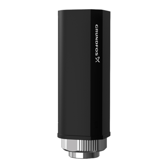
2. Product introduction 2.1 Wireless sensor The wireless sensor is supplied with a lithium thionyl chloride battery and integrates a temperature-vibration measurement module and a communication module. The sensor supports measurement of temperature and vibration, and can transmit the measured data to the Cloud platform using NB-IoT communication protocols. -
Page 8: Identification
3. Identification 3.1 Nameplate of the wireless sensor OLUTION M ON ITOR W .0.N B.CN P. N . : 99982111 Ex.N o . : CN Ex20.0000 Ⅱ Ex.M arking : Ex ia C T4 S. N . : 203200001 IP65 Pos. -
Page 9: Type Key Of The Wireless Sensor
3.2 Type key of the wireless sensor Example: iSOLUTIONS MONITOR W.0.NB.CN Code Explanation Designation iSOLUTIONS Product type MONITOR S: Gateway with wired sensor and IO241 L : Gateway with wired sensor Hardware variant W: Gateway with wireless sensor R: Gateway R3000-4L... -
Page 10: Receiving The Product
Before installing the product, do the following: 1. Check that the product is as ordered. 2. Check that no visible parts have been damaged. 3. If parts are damaged or missing, contact your local Grundfos sales company. 4.2 Supply list 1. -
Page 11: Installation Requirements
5. Installation requirements 5.1 Installation location of sensors • Pump horizontally installed: the sensor is vertically installed on the connection part between the pump and motor. Installation location of the sensor on a pump horizontally installed... - Page 12 • Pump vertically installed: the sensor is vertically installed on the edge of the connection part between the pump and motor. If you want to install the sensor to a vertical pump, make sure that the width of the installation surface meets the minimum requirement.
-
Page 13: Dimensions, Wireless Sensor
5.2 Dimensions, wireless sensor... -
Page 14: Measures Of Ensuring The Quality Of Data Transmission
5.3 Measures of ensuring the quality of data transmission Sensor RF characteristics (in the case of using external antenna): Freuqncy band B3/5/8/20 Total output power 17.3 dBm Receiving sensitivity -103.3 dBm In order to ensure the quality of data transmission, pay attention to the following items when installing sensors: •... -
Page 15: Mechanical Installation
6. Mechanical installation 6.1 Installing the wireless sensor to the pump If you want to install the wireless sensor to a vertical pump, make sure that the width of the installation surface is at least 30 mm. if the width is less than 30 mm, use a bracket to install. See section 6.2 Using the bracket to install the wireless sensor. - Page 16 3. Use AB glue (we recommend ERGO9988.) to stick the fittings to the surface of the equipment. Make sure that you only use the AB glue to stick the base bottom (B) on the equipment surface. Do not stick the nut (A) to the equipment surface.
- Page 17 5. Install the main body of the sensor.
- Page 18 6. Make sure that the X, Y, Z directions marked on the top of the sensor are aligned with the pump. If you need to adjust the direction, loosen the fixed nut first, and then adjust the direction of the sensor. •...
- Page 19 • for vertical pumps: Axial marking on the sensor Axial direction of the pump Circumferential Radial Axial 7. Tighten the nut. The sensor must be firmly installed and cannot fall off. Related information 5.1 Installation location of sensors...
-
Page 20: Using The Bracket To Install The Wireless Sensor
6.2 Using the bracket to install the wireless sensor When the wireless sensor is installed on a vertical pump, and the width of the installation surface is less than 30 mm, you must use the mounting bracket to install the sensor. 1. - Page 21 2. Install the sensor to the bracket. • For the installation method and requirements, see the section 6.1 Installing the wireless sensor to the pump. Make sure that the sensor is firmly installed on the pump and cannot fall off. Related information 5.1 Installation location of sensors...
-
Page 22: Installing The Sim Card
6.3 Installing the SIM card 1. Disassemble the 6 rubber plugs and 6 screws on the sensor. 2. Remove the battery. 3. Insert the SIM card in the direction as illustrated, with the chip side facing downwards. Push the SIM card further into the slot until you hear a "click" sound. - Page 23 4. Install the rubber plugs into the SIM card slot. 5. Install the battery back in a right direction according to the arrow. 6. Tighten the 6 screws and the plugs. If the indicator (A) flashes, it means that the sensor is powered on normally.
-
Page 24: Software Configuration
7. Software configuration 7.1 Adding the wireless sensor to Cloud Platform 1. Open the cloud system through the browser. 2. Enter the Gateway (2) tab, click the CREATE GATEWAY (1) button. - Page 25 3. Key in the GATEWAY NAME (1), select Grundfos (2) in PLATFORM, and key in the unique SN (3) found on the nameplate of the wireless sensor. Select Wireless sensor (4) from the SENSOR TYPE. Click CREATE button. The wireless sensor appears in the gateway list.
- Page 26 4. If you need to configure the parameters for the wireless sensor, click Edit (1) on the right side of the device in the gateway list. • For detailed information on setting the parameters, refer to the online user manual for the Cloud Platform. Related information • Online user manual for Cloud Platform...
-
Page 27: Fault Finding The Product
Do not change the battery by yourself. Contact Grundfos service. The SIM card of the Internet of things 1. Check if the SIM card is in arrears used by the vibration sensor is in through the SIM supplier. - Page 28 ■ Server was unable to display measurement data Under normal circumstances, the data measured by each sensor will be directly uploaded to the MQTT server. If the data of all the sensors on the MQTT server are not updated, please check whether it is due to the following reasons. Cause Remedy MQTT server is in error.
-
Page 29: Operating And Maintaining The Product
Make sure that the power supply cannot be inadvertently reconnected. The product cannot be serviced. • Contact Grundfos. If the product is faulty, it must be replaced. • Do not open the product cover by yourself. Contact the manufacturer when the product doesn't work. - Page 30 9.2.2 Replacing the battery Do not change the battery or any other parts in the wireless sensor by yourself. Always contact Grundfos service if you need to replace the battery. 1. Disassemble the 6 rubber plugs and 6 screws on the sensor.
- Page 31 10. Technical data, wireless sensor Category Property Value Range of acceleration ±5 g Frequency response 3 Hz - 2 kHz (-3 dB) Vibration measurement Sensitivity 160 mV/g ± 10% Axial direction X, Y, Z Measurement range -10 to +110 °C Temperature measurement Accuracy...
- Page 32 This product or parts of it must be disposed of in an environmentally sound way. 1. Use the public or private waste collection service. 2. If this is not possible, contact the nearest Grundfos company or service workshop. The crossed-out wheelie bin symbol on a product means that it must be disposed of separately from household waste.
- Page 33 中文 (CN) 安装和使用说明书 中文版本 目录 概述 ........34 危险性声明...
-
Page 34: 危险性声明
无线传感器技术数据 ......60 产品处置........61 1. -
Page 35: 特别说明
带白色图形符号的蓝色或灰色圆圈表示必须采取行动。 红色或灰色圆圈加一斜线,也可能带黑色图形符号,表示不得采取或 必须停止的行为。 不遵守这些指导可能会造成设备故障或设备损坏。 使工作更轻松的窍门和建议。 1.3 特别说明 在安装和使用产品之前,请务必仔细阅读本安装和使用说明,并严格 按照说明的步骤和工具进行操作。 如果不按照本安装和使用说明操作,导致产品损坏、出现质量问题或无法正常运 行的,格兰富将无法承担质保责任。... -
Page 36: 产品介绍
2. 产品介绍 2.1 智能监测无线传感器 智能监测无线传感器 (以下简称“无线传感器”) 采用锂亚电池供电,集成了温 度、振动测量模块和通讯模块。该产品支持振动和温度的测量,并能利用 NB- IoT 通讯协议将测量数据直接发送至云端。产品具备远程固件升级和边缘计算功 能。 2.2 设计用途 无线传感器用于按照需求定时唤醒并采集设备的温度信号和三轴向振动信号,然 后通过 NB-IoT 的通讯方式发送至云服务器。... - Page 37 3. 标识 3.1 铭牌 OLUTION M ON ITOR W .0.N B.CN P. N . : 99982111 Ex.N o . : CN Ex20.0000 Ⅱ Ex.M arking : Ex ia C T4 S. N . : 203200001 IP65 位置号 描述 传感器三轴向标识 产品型号 产品编号...
-
Page 38: 型号说明
3.2 型号说明 示例: iSOLUTIONS MONITOR W.0.NB.CN 代码 说明 名称 iSOLUTIONS MONITOR 产品型号 S : 配有线传感器和 IO 241 的网关 L : 配有线传感器的网关 硬件类型 W: 配无线传感器的网关 R: 配 R3000-4L 网关 0: 不带有线传感器 1: 一个有线传感器 有线传感器数量 2: 两个有线传感器 WI: 无线版 4G: 4G 蜂窝数据版... -
Page 39: 接收产品
4. 接收产品 4.1 检查产品 安装产品之前,请采取以下措施: 1. 检查产品是否与订单相符。 2. 检查并确保无可见的部件损坏。 3. 如果有部件损坏或丢失,请联系您当地的格兰富销售公司。 4.2 供货清单 • 无线传感器,含电池 • SIM 卡取卡器、防爆证书、合格证、安装和使用说明 (中英文) -
Page 40: 安装要求
5. 安装要求 5.1 传感器安装位置 • 卧式泵: 传感器竖直安装在水泵与电机的连接处的壳体上。 卧式泵传感器安装位置... - Page 41 • 立式泵: 传感器竖直安装在泵与电机的连接处的边沿上。 如果将传感器安装至立式泵,请确保立式泵边沿安装面宽度满足 要求。如宽度不足,请使用安装支架。参见使用支架安装传感器 的相关章节。 立式泵传感器安装位置 相关信息 6.1 安装无线传感器至水泵 6.2 使用安装支架安装无线传感器...
- Page 42 5.2 尺寸, 无线传感器...
-
Page 43: 确保数据传输质量的措施
5.3 确保数据传输质量的措施 传感器节点射频特性 (在使用内置天线条件下): 频段 B3/5/8/20 总辐射功率 17.3 dBm 接收灵敏度 -103.3 dBm 为确保数据传输质量,在安装传感器时应注意: • 使发射节点的天线方向正对基站。 • 尽量使采集节点与基站之间没有直接障碍物。可尽量使采集节点处于较高且 不被遮蔽的位置。 • 尽量架高节点,以防止天线受到地面或者其它平面的衰减。 可能影响通讯质量的因素包括但不限于: 地形特性、障碍物、天线增 益、天线高度、方向、其它无线电干扰以及天气情况等多方面。... -
Page 44: 机械安装
6. 机械安装 6.1 安装无线传感器至水泵 如果将无线传感器安装至立式泵,请确保立式泵边沿安装面宽度至少 为 30 mm。如宽度少于 30 mm,请使用传感器安装支架。参见 6.2 使用安装支架安装无线传感器 。 1. 为了保证传感器和水泵的磁力吸附和胶粘牢固,请先将安装面做如下处理: a. 祛除安装面的漆面。 b. 将除漆后的安装区域轻微打磨成平面。 2. 将固定螺帽安装到传感器固定基座上。 确保固定螺帽的底部 (A) 高于固定基座的底部 (B)。... - Page 45 3. 用 AB 胶水 (推荐 ERGO9988) 将套好的组件粘在设备壳体表面。 确保只有固定基座的底部 (B) 通过 AB 胶粘站在壳体表面。注意不 要把固定螺帽 (A) 也固定住。 4. 放置 24 小时,使胶水完全固化。...
- Page 46 5. 安装无线传感器主体。...
- Page 47 6. 检查并确保传感器顶部的 X、Y、Z 方向标识分别与水泵的三轴方向对齐。 注意 如需调整方向,请先拧松固定螺帽,再调整传感器主体方向。 • 对于卧式泵: 传感器的轴向标识 水泵的三轴方向 周向 轴向 径向...
- Page 48 • 对于立式泵: 传感器的轴向标识 水泵的三轴方向 周向 径向 轴向 7. 拧紧固定螺帽。确保传感器安装牢固,不会掉落。 相关信息 5.1 传感器安装位置...
-
Page 49: 使用安装支架安装无线传感器
6.2 使用安装支架安装无线传感器 当将无线传感器安装至立式泵,且立式泵边沿安装面宽度不足 30 mm 时,必须 使用安装支架安装传感器。 1. 将安装支架安装至水泵的螺柱上。 • 建议安装螺柱直径小于 16 mm,螺帽外径 (φ): 17 < φ < 30 mm。... - Page 50 2. 将传感器安装至安装支架。 • 6.1 安装无线传感器至水泵 安装方式及安装要求请参考 。 确保传感器安装牢固,不会掉落。 相关信息 5.1 传感器安装位置...
-
Page 51: 安装 Sim 卡
6.3 安装 SIM 卡 1. 将传感器机身上 6 个橡胶塞和 6 个螺丝拆除。 2. 取下电池模块。 3. 将 SIM 卡按照图示方向 (芯片朝下) 插入卡槽。 SIM 卡安装时要尽量往里推入,当听到“喀哒”声音时表明 SIM 卡安装到位。... - Page 52 4. 塞入橡胶塞。 5. 将电池按照箭头朝上的方向重新安装。 6. 拧紧机身 6 个螺丝并安装橡胶塞。 如看到指示灯(A)闪烁,表明传感器已正常上电。...
-
Page 53: 软件配置
7. 软件配置 7.1 将无线传感器配置到云端 1. 通过浏览器打开云端系统。 2. 进入 网关管理 (2) 标签页,点击右上方 创建网关 (1) 按钮。... - Page 54 3. 输入自定义的 网关名称 (1),在下方的 PLATFORM 选择 Grundfos (2),并输 入无线传感器铭牌上的 SN 号 (3)。SENSOR TYPE 选择 无线传感器 (4)。完 成后点击 创建 按钮。 网关列表中将出现新创建的无线传感器。...
- Page 55 4. 如需修改传感器参数,可点击网关列表右侧 编辑 (1) 按钮,对所选传感器参 数进行编辑。 • 关于参数设置的详细信息,请参考云平台用户手册。 相关信息 云平台在线用户手册 •...
-
Page 56: 故障查寻
8. 故障查寻 ■ 服务器无法获取测量数据 正常情况下,传感器每隔 90 分钟采集一次振动数据,并将数据发送到指定 MQTT 服务器。 若出现某个传感器持续未上传数据,请排查是否为以下原因。 原因 纠正方法 该传感器所处环境信号很差 1. 观察传感器周围是否形成信号屏蔽空 间,或使用专用信号强度监测设备检 测 (手机信号强度亦可侧面反映)。 5.3 确保数据传 2. 若信号较差,则参考 输质量的措施 的措施中的建议措施 进行操作。 该传感器电池耗尽 1. 取下电池再重新安装。 2. 观察: 重新装上电池瞬间,指示灯是 否亮起。 3. 若未亮起,表明电池电量已耗尽,需 更换电池。 请勿自行更换电池。联系 格兰富服务人员。 该传感器所使用的物联网 SIM 卡欠费 1. 通过 SIM 卡供应商查询 SIM 是否欠 费。... - Page 57 ■ 传感器脱落 正常情况下,按照安装及使用说明进行安装的传感器不易脱落。 应用现场出现极少数个别脱落属于偶发性现象, 重新安装即可。 若某个传感器频繁脱落或现场大面积脱落,请排查是否为以下原因。 原因 纠正方法 • 未使用指定型号或同等性能的胶 • 按照安装和使用说明指定的安装方法 水 重新安装。 • 安装传感器时,胶水未完全固化 • 传感器与设备壳体的接触面过小 • 传感器安装处的设备壳体表面不 清洁、有漆面或油污 • 传感器存在人为损坏 • 传感器未竖直安装...
-
Page 58: 产品使用及维护
9. 产品使用及维护 9.1 产品日常使用注意事项 • 产品使用过程中,请注意防止掉落砸伤。 • 请勿将传感器节点投入火中。 • 避免安装在全封闭的金属柜内。 • 在长时间不使用节点的时候,请将其搁置于凉爽、干燥的地方。 在使用过程中,如果节点一直处于低温状态或高温环境下,节点 的正常工作寿命会缩短。 • 所配备电池为一次性电池。电量耗尽后,请更换原厂专用电池。 请勿自行更换电池或任何传感器部件。如需更换电池,请联系格 兰富服务人员。 9.2 产品维护 危险 电击 死亡或重度人身伤害 ‐ 对产品进行任何操作之前必须关闭电源。 ‐ 确保电源关闭后不会被意外打开。 该产品无法维修。 • 联系格兰富。 如果产品出现故障,必须更换。 • 请勿自行打开产品外壳,如有故障须联系厂家。 9.2.1 清洁产品 只能用干净的干布或沾有肥皂水的湿布清洁产品。... - Page 59 9.2.2 更换电池 请勿自行更换电池或任何传感器部件。如需更换电池,请联系格兰富 服务人员。 1. 将传感器机身上 6 个橡胶塞和 6 个螺丝拆除。 2. 取下旧的电池模块 (753)。 3. 将新的电池模块 (753) 安装到传感器。 4. 拧紧机身 6 个螺丝并安装橡胶塞。 如看到指示灯(A)闪烁,表明传感器已正常上电。...
- Page 60 10. 无线传感器技术数据 类别 属性 数值 加速范围 ±5 g 频响范围 3 Hz - 2 kHz (-3 dB) 振动测量 灵敏度 160 mV/g ± 10% 方向 X, Y, Z 测量范围 -10 至 +110 ℃ 温度测量 精度 ±3 ℃ 信号类型 数字, 无线 接口类型 NB-IoT 采样间隔...
- Page 61 11. 产品处置 本产品或其部件必须按环保方法进行处理。 1. 使用当地的公共和个人废物处理设施。 2. 如果不能采用当地的公共和个人废物处理设施,请联系最近的格兰富公司或 者维修站。 产品上打叉的垃圾桶符号的意思是它必须与家庭垃圾分开处理。 当带有此符号的产品达到使用寿命时,请将其送至当地废物处理 机构指定的收集点。 单独收集和回收这些产品有助于保护环境和 人类健康。 www.grundfos.com/product-recycling 另请参阅...
- Page 62 Appendix A A.1. China RoHS, table C...
- Page 63 Argentina Brazil Czech Republic Bombas GRUNDFOS de Argentina BOMBAS GRUNDFOS DO GRUNDFOS Sales Czechia and S.A. BRASIL Slovakia s.r.o. Ruta Panamericana km. Av. Humberto de Alencar Castelo Čajkovského 21 37.500industin Branco, 630 779 00 Olomouc 1619 - Garín Pcia. de B.A.
- Page 64 Tel.: +82-2-5317 600 Fax: +47-22 32 21 50 Kowloon Fax: +82-2-5633 725 Poland Tel.: +852-27861706 / 27861741 Latvia GRUNDFOS Pompy Sp. z o.o. Fax: +852-27858664 SIA GRUNDFOS Pumps Latvia ul. Klonowa 23 Hungary Deglava biznesa centrs Baranowo k. Poznania GRUNDFOS Hungária Kft.
- Page 65 Slovakia Turkey GRUNDFOS s.r.o. GRUNDFOS POMPA San. ve Tic. Prievozská 4D 821 09 Ltd. Sti. BRATISLAVA Gebze Organize Sanayi Bölgesi Tel.: +421 2 5020 1426 Ihsan dede Caddesi sk.grundfos.com 2. yol 200. Sokak No. 204 41490 Gebze/ Kocaeli Slovenia Tel.: +90 - 262-679 7979 GRUNDFOS LJUBLJANA, d.o.o.
- Page 66 99985630 05.2021 ECM: 1314153...
Need help?
Do you have a question about the iSOLUTIONS and is the answer not in the manual?
Questions and answers