Table of Contents
Advertisement
Quick Links
SBM 100
3-PHASE ENERGY SUBMETER
WITH DEMAND
Instruction Manual
Doc # E104720 V1.03
January 21, 2005
Electro Industries/GaugeTech
1800 Shames Drive
Westbury, New York 11590
Tel: 516-334-0870
Fax: 516-338-4741
E-mail:sales@Electroind.com
www.electroind.com
"The Leader in Web Accessed Power Monitoring and Control"
Advertisement
Table of Contents

Related Manuals for Electro Industries/GaugeTech SBM 100


Summary of Contents for Electro Industries/GaugeTech SBM 100
- Page 1 SBM 100 3-PHASE ENERGY SUBMETER WITH DEMAND Instruction Manual Doc # E104720 V1.03 January 21, 2005 Electro Industries/GaugeTech 1800 Shames Drive Westbury, New York 11590 Tel: 516-334-0870 Fax: 516-338-4741 E-mail:sales@Electroind.com www.electroind.com “The Leader in Web Accessed Power Monitoring and Control”...
- Page 2 516-334-0870 or fax 516-338-4741. Product Warranty Electro Industries/GaugeTech warrants all products to be free from defects in material and workmanship for a period of four years from the date of shipping. During the warranty period, we will, at our option, either repair or replace any product that proves to be defective.
-
Page 3: Table Of Contents
Single Phase System Three Phase System Consumption, Demand, and Power Factor Losses Waveform and Harmonics CHAPTER 2 MECHANICAL INSTALLATION Face of the SBM 100 with lower cover removed Relay detail Mounting detail for SBM 100 CHAPTER 3 ELECTRICAL INSTALLATION Section 3.1... - Page 4 Group 5, Functions 0-1 - LMT1/LMT2 Set Limits CHAPTER 13 EXITING THE PROGRAMMING MODE Reserved Groups, Functions and Packs APPENDIX A Quick Reference APPENDIX B APPENDIX C Open Delta System Installation Programming Modbus Mapping for SBM 100 APPENDIX D Electro Industries/GaugeTech Doc # E104720 V1.03...
-
Page 5: Ac Power Measurement
Figure 1.2 shows a triangle which is a graphic Reactive Apparent Power (VA) Power representation of the relationships between apparent, (VAR) real, and reactive power. Power Factor PF: The ratio between real power and apparent power: Real Power (W) Figure 1.2 Electro Industries/GaugeTech Doc # E104720 1.03... -
Page 6: Three Phase System
Wye connection. AB A CB C (See Figure 1.4). CB C AN A BN B 2) Wye P = E I + E CN C Figure 1.4 Poly Phase System: 1) Delta 2) Wye Electro Industries/GaugeTech Doc # E104720 V1.03... -
Page 7: Consumption, Demand, And Power Factor Losses
⋅ ofTHD RMSoftheFu ndamentalS ignal HARMONIC DISTORTION: A destructive force in power distribution systems. It creates safety problems, shortens the life span of distribution transformers, and interferes with the operation of electronic devices. Electro Industries/GaugeTech Doc # E104720 V1.03... - Page 8 Electro Industries/GaugeTech Doc # E104720 V1.03...
-
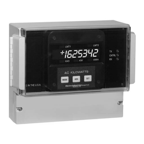
Page 9: Chapter 2 Mechanical Installation
Face of the SBM 100 with lower cover removed. NOTE: Mounting of the SBM 100 is very easy, because it requires no cutting. The meter is mounted with five screws and all wiring can be done through the front panel just below the face of the meter. Wiring can also be done through the back of the meter, if desired. -
Page 10: Mounting Detail For Sbm 100
SBM 100. NOTE: Mounting of the SBM 100 is very easy, because it requires no cutting. The meter is mounted with five screws as shown and all wiring can be done through a front panel just below the face of the meter. -
Page 11: Chapter 3 Electrical Installation
If the SBM 100 is connected directly, maintain the exact connection to avoid incorrect polarity. When the SBM 100 is connected using the CTs, it is imperative to maintain the correct CT polarities. CT polarities are dependent upon correct connections of CT leads and the direction that the CTs are facing when they are clamped around the conductors. -
Page 12: Connection To The Main Power Supply
ONNECTION TO THE OWER UPPLY The SBM 100 requires a separate power supply. Listed are the 5 different power supply options and corresponding suffixes. CONTROL POWER OPTION 120V AC UFFIX 240V AC 24V DC 48V DC 125V DC NOTE: F... -
Page 13: Three-Phase, Three-Wire Delta With Direct Voltage And Cts
I. Three Phase, Three-Wire System Delta with Direct Voltage and three CTs. Electro Industries/GaugeTech Doc # E104720 V1.03... -
Page 14: Three-Phase, Three-Wire Delta With 2 Cts And 2 Pts
II. Three-Phase, Three-Wire Open Delta with two CTs and two PTs. Electro Industries/GaugeTech Doc # E104720 V1.03... -
Page 15: Iii. Three-Phase, Three-Wire Open Delta With Three Cts And Two Pts
III. Three-Phase, Three-Wire Open Delta with three CTs and two PTs. Electro Industries/GaugeTech Doc # E104720 V1.03... -
Page 16: Three-Phase, Four-Wire System Wye With Direct Voltage And Cts
IV. Three-Phase, Four-Wire System Wye with Direct Voltage and three CTs. Electro Industries/GaugeTech Doc # E104720 V1.03... -
Page 17: Three-Phase, Four-Wire System Wye With Cts And Pts
V. Three-Phase, Four-Wire System Wye with three CTs and three PTs. Electro Industries/GaugeTech Doc # E104720 V1.03... -
Page 18: Three-Phase, Four Wye 2-1/2 Element With Cts And Pts
VI. Three-Phase, Four-Wire System Wye 2.5 Element with three CTs and two PTs. For this installation, SBM100-2.5E (Only) must be specified when ordering. Electro Industries/GaugeTech Doc # E104720 V1.03... -
Page 19: Relays, Protection And Pulse Output
This section is applicable only if the -NL Relay Option was ordered. The SBM 100 accesses a variety of relay options through the Programming Mode. The relay option package consists of two relays with two contacts. One is normally open and one is normally closed (either to alarm or communication, or both), and one is KYZ pulse output. - Page 20 Electro Industries/GaugeTech Doc # E104720 V1.03...
-
Page 21: Chapter 4 Communication Installation
CHAPTER 4 COMMUNICATION INSTALLATION RS-485 CONNECTION TERMINAL BLOCK TO RELAY OUTPUT #1 TO RELAY OUTPUT #2 TO KYZ OUTPUTS Figure 4.1: Wiring Diagram of SBM 100 RS-485 Communication and Relay Output Installation. Electro Industries/GaugeTech Doc # E104720 V1.03... -
Page 22: Rs-485 Communication Connection
Figure 4.2 RS-485 Communication Connection Electro Industries/GaugeTech Doc # E104720 V1.03... -
Page 23: Network Of Instruments And Long Distance Communication
RS-485 Each SBM 100 instrument has an unique address up to four digits. Available standard baud rates are available up to 4800 baud. To select the proper baud rate, apply the following rules: For a smaller number of instruments over a long distance, use a lower baud rate. Optimal recommended baud rate is 1200 baud. -
Page 24: Modem Connected To The Device
Necessary to communicate with remote modem connected to the Futura+ Series ELL THE ODEM TO RITE THE ETTINGS TO CTIVATE ROFILE Places new settings into nonvolatile memory; settings take effect after the modem powers up. Electro Industries/GaugeTech Doc # E104720 V1.03... -
Page 25: Chapter 5 Sbm 100 Overview
The SBM 100 measures electrical power demand and energy for usage monitoring, cost allocation, load monitoring or demand tracking and control. The digital display is intuitive and requires virtually no user training. Open Modbus digital communication protocol ensures simple interface to any digital control or monitoring system. The SBM 100 is a basic energy/demand meter. -
Page 26: Accessing Kw, Kwd, Kwh
A C KILOWATTS MODE MODE MODE Step 1: Step 2: Upon power up, the SBM 100 a. To access the kilowatt demand a. Press MODE once more to monitors instantaneous kilowatts and access kilowatt hour reading and reading, press MODE once and KW glows. -
Page 27: Protected Reset
Three dashes appear on the right side. After entering the correct password, the display blanks A single digit begins scrolling on the left side. and the KWH reading resets to 000.000. a. Press SET to select the appropriate digits. Electro Industries/GaugeTech Doc # E104720 V1.03... - Page 28 CCESSING THE IMITS The SBM 100 has two manual set limits that monitor the instantaneous readings, warning the user of any abnormal conditions. Each limit detects readings either above or below the set level. SET LIMITS: The point when the relay changes position if the SBM 100 is equipped with the Relay Option Package (Suffix -NL).
-
Page 29: Printing Operating Data
RINTING PERATING This function applies only if a serial printer is connected to the SBM 100 via an RS-232C Communication Converter. This function sends the data to a serial printer. This allows a hard copy of the instantaneous data for KW, KWD and KWH to compile without manually copying the data. -
Page 30: Firmware Version/Led Test
222 appears momentarily to confirm printing. /LED T IRMWARE ERSION The SBM 100 accesses the firmware version number of the analog and digital microprocessors. Also, the LED test checks if the LED’s and annunciators are functioning properly. I.8.8.8.8.8.8. A C KILOWATTS... -
Page 31: Chapter 6 Programming Overview
GROUPS are the main category. • Functions are sub categories of GROUPS. • Switch PACKS categories FUNCTIONS. FUNCTION AC KILOWATTS MODE The diagram below illustrates the arrangement of the three categories: GROUPS Functions Switch PACKS Electro Industries/GaugeTech Doc # E104720 V1.03... -
Page 32: Programming Mode Data Entry
ROGRAMMING NTRY The SBM 100 programming mode utilizes all three keypad buttons. SED FOR ASSWORD NTRY AC KILOWATTS MODE ADV. SED FOR ROGRAMMING BUTTON FUNCTION DESCRIPTION MODE ADVANCES Scrolls groups, functions, and advances to exit point from function and group level. -
Page 33: Chapter 7 Entering The Programming Mode
MUST BE IN THE MODE The SBM 100 is password protected. To enter the Programming Mode, key in the following password. The password is 555. The password entry may seem awkward at first. It is designed initially be difficult to use. This secures unauthorized tampering. - Page 34 Electro Industries/GaugeTech Doc # E104720 V1.03...
-
Page 35: Programming Group
When complete, a decimal appears next to the function number and the new Integration Interval appears to the b. Press ADV. for desired number right. See Chapter 13 to Exit. c. Press SET to store. Electro Industries/GaugeTech Doc # E104720 V1.03... -
Page 36: Group 0, Function 1 - The Meter Address
BAUD RATE: Speed at which data is transmitted between meter and remote computer or serial printer. The rate programmed into the meter must match the rate used by the remote device. Valid Baud Rates are 110, 150, 300, 600, 1200, 2400, 4800 and 9600. Electro Industries/GaugeTech Doc # E104720 V1.03... -
Page 37: Group 0, Function 3 - System Configuration (Programming Options)
ROUP UNCTION YSTEM ONFIGURATION The System Configuration sets the SBM 100's basic operational parameters. This Function utilizes Switch PACKS (See SWITCH PACKS). Function 3 contains four separate Switch PACKS: 0 - 3. Each PACK contains four individual UP/DOWN segments. •... -
Page 38: System Configuration - Switch Features
Trip Relay Computer Control UP Enable (Relay Control 1 and 2 apply only if Relay Option -NL was DOWN Disable ordered) Trip Relay Computer Control 2 UP Enable DOWN Disable Communications UP Enable DOWN Disable Electro Industries/GaugeTech Doc # E104720 V1.03... - Page 39 (example below) to exist for a user specified time period before the relay or alarm activates. If a time greater than 255 seconds is entered, the meter defaults to the maximum value of 255 seconds. Electro Industries/GaugeTech Doc # E104720 V1.03...
- Page 40 The previous value shifts and is replaced with four number and the new Delay Time appears to the right. dashes. NOTE: Default of 0255 is the highest setting. b. Press ADV. for the desired number. c. Press SET to store. Electro Industries/GaugeTech Doc # E104720 V1.03...
-
Page 41: Programming Group
300 V 1000 A • 1000 A FSW (one element) 300 V FSW (one element) 300,000 W • 3 = 900,000 W (or 900 KW) FSW (three element) 300, 000 W FSW enter 0900 KW. Electro Industries/GaugeTech Doc # E104720 V1.03... - Page 42 The current setting is replaced by a single dash to the position. far right. The Function Number remains on the far left. b. Press SET to store. b. Press ADV. to toggle. UP - Megawatts DOWN - Kilowatts c. Press SET to store. Electro Industries/GaugeTech Doc # E104720 V1.03...
- Page 43 Press SET to select. To the right the new Scale Factor, Full Scale and Decimal Point Placement Settings appear. Repeat this procedure until entire Full Scale is entered. See Chapter 13 to Exit. Electro Industries/GaugeTech Doc # E104720 V1.03...
- Page 44 Electro Industries/GaugeTech Doc # E104720 V1.03...
-
Page 45: Programming Group
EQUIREMENTS Calibration on the SBM 100 requires precise inputs of 120 Volts, and 5 Amps. The SBM 100 Suffix -G model requires precise inputs of 300 Volts and 5 amps. If this equipment is unavailable contact, the factory for assistance. -
Page 46: Group 2, Functions 0-1 - High And Low End Watts Calibration
High End Calibration for Watts. b. Press MODE until P2. appears. c. Press SET to activate the Group. A one digit password is required to continue. d. Press ADV. until 5 appears. e. Press SET to select. Electro Industries/GaugeTech Doc # E104720 V1.03... - Page 47 Press SET to store. b. Press ADV. for the desired digit. If the calibrated reading is unacceptable, repeat the c. Press SET to select. entire procedure after checking all connections and calibration inputs. Electro Industries/GaugeTech Doc # E104720 V1.03...
- Page 48 Press MODE to begin Data entry Sequence. a. Press MODE to store. d. Press ADV. for desired digits. You cannot cancel at this time. e. Press SET to store. See Chapter 13 to Exit. Electro Industries/GaugeTech Doc # E104720 V1.03...
-
Page 49: Programming Group 3
CHAPTER 11 PROGRAMMING GROUP 3 The SBM 100 is constructed with two separate modules, joined by a connector and secured with two screws. The front module (meter module) contains the microprocessors, displays and related circuitry. The rear (input module) supports all incoming signal connections. The sections can be easily separated, allowing the meter module to move or serviced off-site without interrupting service loops or removing meter connections. - Page 50 Press ADV. for the desired digits. number and the new Correction Ratio appears to the right. b. Press SET to select. Repeat this procedure until the new Correction Ratio See Chapter 13 to Exit. is entered. Electro Industries/GaugeTech Doc # E104720 V1.03...
-
Page 51: Programming Group 5
CHAPTER 12 PROGRAMMING GROUP 5 Set Limits alert the user when a particular power level changes. The Set Limits on the SBM 100 are LMT1 and LMT2. Each limit can be set at any desired level. Group 5 contains LMT1 and LMT2 Set Limit Values for Watts. The user can program the limits for positive and negative Watts. - Page 52 Digit Down Digit Down Digit Up 0090 EXAMPLE: If Kilowatts exceed 120W, LMT1 is triggered and Relay 1 is enabled. If the Kilowatts do not exceed 90W, LMT2 is triggered and Relay 2 is enabled. Electro Industries/GaugeTech Doc # E104720 V1.03...
- Page 53 Set Limits or to Disable the Limits. b. Press ADV. twice to skip programming of Limit 1 and proceed to Limit 2. c. Press ADV. three times to view the Setup Level for Limit 2. Electro Industries/GaugeTech Doc # E104720 V1.03...
- Page 54 Press ADV to see the Limit Value. e. After the fourth digit is stored, the display reverts back to the segment setting and the decimal point will reappear after the Function 0 digit. See Chapter 13 to Exit. Electro Industries/GaugeTech Doc # E104720 V1.03...
-
Page 55: Chapter 13 Exiting The Programming Mode
ROUP EVEL a. Press MODE until PE. appears. b. Press SET to exit entirely from the Programming Mode. You have exited the Programming Mode. After a moment the meter returns to the Operating Mode. Electro Industries/GaugeTech Doc # E104720 V1.03... - Page 56 Electro Industries/GaugeTech Doc # E104720 V1.03...
-
Page 57: Reserved Groups, Functions And Packs
AILURE TO SELECT THIS SWITCH RESULTS IN HASE EUTRAL READINGS Follow the special Open Delta Connection Installation. (See Chapter 3). SBM 100 ODBUS APPING FOR The Modbus Mapping for the SBM 100 Meter is on the following pages. Electro Industries/GaugeTech Doc # E104720 V1.03... - Page 58 APPENDIX D Modbus Mapping for SBM 100 Register Address Description Range Unit Meter Profile Block 0x0000 0x0020 B15-VAN B14-VBN B13-VCN B12-VAB B11-VBC B10-VCA B9-IA B8-IB B7-IC B6-IN B5-Watts B4-VAR B3-VA B2-PF B1-FQ B0-n/a 0X0002 0X0008 B15-KFVA B14-KFVB B13-KFVC B12-KFIA B11-KFIB...
- Page 59 APPENDIX D Modbus Mapping for SBM 100 Register Address Description Range Unit 0x002B Config 0xFFFF B13-MW B11-LZ B10-RST B8-DLT B7-KYZ for WH B6-KYZ for -WH B4-Modbus/EI protocol B3-RLY1 B2-RLY2 B1-COM B0-DC 0x002C Watt Full Scale 0…2000 0x002F Power DP only High byte...
-
Page 60: Modbus Mapping For Sbm 100
APPENDIX D Modbus Mapping for SBM 100 Register Address Description Range Unit Reset Block 0x0504 Setting bits will reset the values B5-(+,-)MAX Watt B3-(+,-)Watt Hour Negative MAX/MIN Block 0x050A Negative MAX. Watt -9999…0 Negative Hour Block 0x09BA-0x09C1 Negative Watt Hour 0~19999999.99...
Need help?
Do you have a question about the SBM 100 and is the answer not in the manual?
Questions and answers