Table of Contents
Advertisement
Quick Links
Advertisement
Table of Contents

Related Manuals for Electro Industries/GaugeTech Shark 100


Summary of Contents for Electro Industries/GaugeTech Shark 100
- Page 1 V.1.34 February 4, 2021...
- Page 2 This page intentionally left blank.
- Page 3 Electro Industries/GaugeTech. © 2021 Electro Industries/GaugeTech Nexus®, Shark®, CommunicatorPQA®, MeterManagerPQA®, EnergyPQA®, and EnergyPQA.com®are registered trademarks of Electro Industries/GaugeTech. The dis- tinctive shape, style, and overall appearances of all Shark® meters are trademarks of Electro Industries/GaugeTech. EnergyReporterPQA , HMIPQA , and V-Switch trademarks of Electro Industries/GaugeTech.
- Page 4 This page intentionally left blank. Electro Industries/GaugeTech ™ E145701 Powered by Innovation™...
- Page 5 IMPLIED, GIVEN BY ELECTRO IN CONNECTION WITH THE PRODUCT, AND ELECTRO DISCLAIMS ALL OTHER WARRANTIES, INCLUDING BUT NOT LMITED TO WARRANTIES OF MERCHANTABILITY, FITNESS FOR A PARTICULAR PURPOSE, NON-INFRINGEMENT OF THIRD-PARTY RIGHTS AND WARRANTIES AGAINST LATENT DEFECTS. The Cus- Electro Industries/GaugeTech ™ E145701 Powered by Innovation™...
- Page 6 SION SHALL APPLY EVEN IF THE EXPRESS LIMITIED WARRANTY SET FORTH ABOVE FAILS OF ITS ESSENTIAL PURPOSE. EXCEPT AS EXPRESSLY PROVIDED IN THIS SECTION, ELECTRO HEREBY DISCLAIMS AND CUSTOMER WAIVES ALL REPRESENTATIONS, CONDITIONS AND WARRANTIES Electro Industries/GaugeTech ™ E145701 Powered by Innovation™...
- Page 7 ELECTRO'S TOTAL LIABILITY FOR ALL DAMAGES, LOSSES, OR CAUSES OF ACTION OF ANY KIND OR NATURE SHALL BE LIMITED TO CUSTOMER'S PURCHASE PRICE FOR THE PRODUCT LICENSED BY THE CUSTOMER FROM ELECTRO, WHICH GAVE RISE TO Electro Industries/GaugeTech ™ E145701...
-
Page 8: Use Of Product For Protection
Statement of Calibration Our instruments are inspected and tested in accordance with specifications published by Electro Industries/GaugeTech. The accuracy and a calibration of our instruments are traceable to the National Institute of Standards and Technology through equipment that is calibrated at planned intervals by comparison to certified standards. - Page 9 Ce symbole indique que la borne de pose des canalisations in-situ qui doit être branchée dans la mise à terre avant de faire fonctionner le compteur qui est protégé contre une décharge électrique ou un état défectueux. Electro Industries/GaugeTech ™ E145701...
-
Page 10: About Electro Industries/Gaugetech (Eig)
GaugeTech changed the face of power monitoring forever with its first breakthrough innovation: an affordable, easy-to-use AC power meter. More than forty years since its founding, Electro Industries/GaugeTech, the leader in power monitoring and control, continues to revolutionize the industry with the highest quality, cutting edge power monitoring and control technology on the market today. -
Page 11: Table Of Contents
Customer Service and Support Product Warranty Use of Product for Protection Statement of Calibration Disclaimer About Electro Industries/GaugeTech (EIG) 1: Three-Phase Power Measurement 1.1: Three-Phase System Configurations 1.1.1: Wye Connection 1.1.2: Delta Connection 1.1.3: Blondel’s Theorem and Three Phase Measurement 1.2: Power, Energy and Demand... - Page 12 4.9: Extended Surge Protection for Substation Instrumentation 4-21 5: Communication Installation 5.1: Shark® 100/50 Meter Serial Based Communication 5.1.1: IrDA Port (Com 1) 5.1.2: RS485/KYZ Output Com 2 (485P Option) 5.1.2.1: Using the Unicom 2500 Electro Industries/GaugeTech ™ E145701 TOC-2 Powered by Innovation™...
- Page 13 6.2.2: Using the Main Menu 6.2.3: Using Reset Mode 6.2.4: Entering a Password 6.2.5: Using Configuration Mode 6.2.5.1: Configuring the Scroll Feature 6.2.5.2: Configuring CT Setting 6-10 6.2.5.3: Configuring PT Setting 6-11 Electro Industries/GaugeTech ™ E145701 TOC-3 Powered by Innovation™...
- Page 14 8.1: Introduction 8.2: Shark® 50B Meter’s BACnet Objects 8.3: Configuring the Shark® 50B Meter 8.4: Using the Shark® 50B Meter’s Web Interface 8-11 8.5: Using the Shark® 50B in a BACnet Application 8-17 Electro Industries/GaugeTech ™ E145701 TOC-4 Powered by Innovation™...
- Page 15 D.4.1.2: Control Relay Output Block (Obj. 12, Var. 1) D.4.1.3: 32-Bit Binary Counter Without Flag (Obj. 20, Var. 5) D.4.1.4: 16-Bit Analog Input Without Flag (Obj. 30, Var. 4) D.4.1.5: Class 0 Data (Obj. 60, Var. 1) D-13 Electro Industries/GaugeTech ™ E145701 TOC-5 Powered by Innovation™...
- Page 16 Table of Contents D.4.1.6: Internal Indications (Obj. 80, Var. 1) D-13 E: Using the USB to IrDA Adapter CAB6490 E.1: Introduction E.2: Installation Procedures Electro Industries/GaugeTech ™ E145701 TOC-6 Powered by Innovation™...
-
Page 17: 1: Three-Phase Power Measurement
This leads to common voltages of 208/ 120 and 480/277 (where the first number represents the phase-to-phase voltage and the second number represents the phase-to-ground voltage). Electro Industries/GaugeTech ™ E145701 Powered by Innovation™... - Page 18 A phasor diagram for the typical connected voltages and currents is shown in Figure 1.2. Figure 1.2: Phasor Diagram Showing Three-phase Voltages and Currents Electro Industries/GaugeTech ™ E145701 Powered by Innovation™...
- Page 19 Table 1, even though a neutral or ground wire is not physically present at the load. The transformer is the best place to determine the circuit connection type because this is a location where the voltage reference to ground can be conclusively identified. Electro Industries/GaugeTech ™ E145701 Powered by Innovation™...
-
Page 20: 2: Delta Connection
In many delta services, one corner of the delta is grounded. This means the phase to ground voltage will be zero for one phase and will be full phase-to-phase voltage for the other two phases. This is done for protective purposes. Electro Industries/GaugeTech ™ E145701... - Page 21 208 volts on the third phase. Figure 1.5 shows the phasor diagram for the voltages in a three-phase, four-wire delta system. Figure 1.5: Phasor Diagram Showing Three-phase Four-Wire Delta-Connected System Electro Industries/GaugeTech ™ E145701 Powered by Innovation™...
-
Page 22: 3: Blondel's Theorem And Three Phase Measurement
The difference in modern meters is that the digital meter measures each phase volt- age and current and calculates the single-phase power for each phase. The meter then sums the three phase powers to a single three-phase reading. Electro Industries/GaugeTech ™ E145701... - Page 23 If we measure the currents in wires A, B and C, we then know the current in wire N by Kirchhoff's Law and it is not necessary to measure it. This fact leads us to the conclusion of Blondel's Theorem- that we only need to measure the power in three of Electro Industries/GaugeTech ™ E145701...
-
Page 24: Power, Energy And Demand
The data from Figure 1.7 is reproduced in Table 2 to illustrate the calculation of energy. Since the time increment of the measurement is one minute and since we Electro Industries/GaugeTech ™ E145701... - Page 25 1/ 60 (converting the time base from minutes to hours). Time (minutes) Figure 1.7: Power Use over Time Electro Industries/GaugeTech ™ E145701 Powered by Innovation™...
- Page 26 15-minute interval. To convert the reading to a demand value, it must be normalized to a 60-minute interval. If the pattern were repeated for an additional three 15-minute intervals the total energy would be four times the measured value or Electro Industries/GaugeTech ™ E145701 1-10 Powered by Innovation™...
- Page 27 Figure 1.8: Energy Use and Demand As can be seen from this example, it is important to recognize the relationships between power, energy and demand in order to control loads effectively or to monitor use correctly. Electro Industries/GaugeTech ™ E145701 1-11...
-
Page 28: Reactive Energy And Power Factor
The quadrature current may be lagging the voltage (as shown in Figure 1.9) or it may lead the voltage. When the quadrature current lags the voltage the load is requiring both real power (watts) and reactive power (VARs). When the quadrature current Electro Industries/GaugeTech ™ E145701 1-12 Powered by Innovation™... - Page 29 Displacement power factor does not consider the magnitudes of voltage, current or power. It is solely based on the phase angle differences. As a result, it does not include the impact of Electro Industries/GaugeTech ™ E145701 1-13 Powered by Innovation™...
-
Page 30: Harmonic Distortion
Figure 1.11 shows a current waveform with a slight amount of harmonic distortion. The waveform is still periodic and is fluctuating at the normal 60 Hz frequency. However, the waveform is not a smooth sinusoidal form as seen in Figure 1.10. Electro Industries/GaugeTech ™ E145701 1-14 Powered by Innovation™... - Page 31 Figure 1.11. 1000 Time 3rd harmonic 5th harmonic – 500 7th harmonic Total fundamental Figure 1.12: Waveforms of the Harmonics Electro Industries/GaugeTech ™ E145701 1-15 Powered by Innovation™...
- Page 32 It is common in advanced meters to perform a function commonly referred to as waveform capture. Waveform capture is the ability of a meter to capture a present picture of the voltage or current waveform for viewing and harmonic analysis. Electro Industries/GaugeTech ™ E145701 1-16 Powered by Innovation™...
-
Page 33: Power Quality
In his book Power Quality Primer, Barry Kennedy provided information on different types of power quality problems. Some of that information is summarized in Table 1.3. Electro Industries/GaugeTech ™ E145701 1-17... - Page 34 If a power quality problem is suspected, it is generally wise to consult a power quality professional for assistance in defining the cause and possible solutions to the problem. Electro Industries/GaugeTech ™ E145701 1-18...
-
Page 35: 2: Meter Overview And Specifications
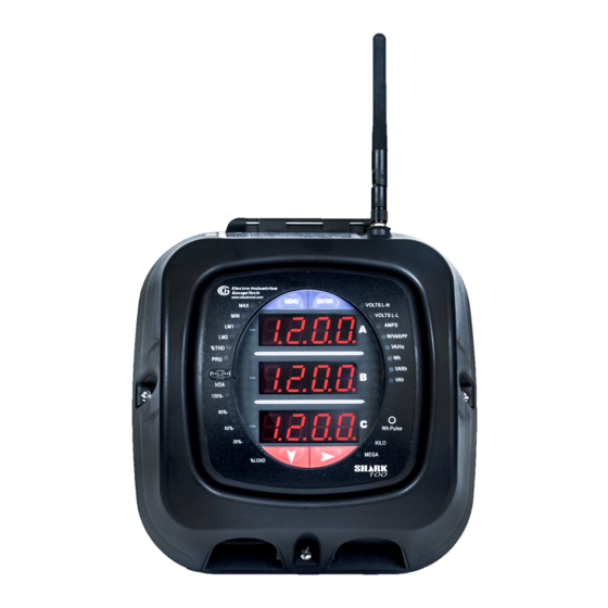
The Shark® 100 meter is designed with advanced measurement capabilities, allowing it to achieve high performance accuracy. The Shark 100® meter is specified as a 0.2% class energy meter for billing applications as ® Figure 2.1: Shark 100 Meter well as a highly accurate panel indication meter. - Page 36 The Shark® 100B meter's BACnet/IP has 62 predefined BACnet objects that let you track up to 62 measurements. No programming or mapping is necessary to use the BACnet objects. (The Shark® 50B also supports BACnet communication - see the next page for a description.) Electro Industries/GaugeTech ™ E145701 Powered by Innovation™...
- Page 37 BACnet MS/TP settings and track energy usage through the Internet using a standard browser. You can also access all of the Shark® 50B meter’s readings through CommunicatorPQA® software. See Chapter 6 for more Electro Industries/GaugeTech ™ E145701...
-
Page 38: 1: Voltage And Current Inputs
CT leads to be terminated on the meter. This, too, eliminates any possible point of failure at the meter. This is a preferred technique for insuring that relay class CT integrity is not compromised (the CT will not open in a fault condition). Electro Industries/GaugeTech ™ E145701... -
Page 39: 2: Model Number Plus Option Numbers
90-265 ANSI Meter/ System Secondary VAC or Mounting Transducer 100-370 Shark® 100BT 60 Hz 1 Amp 18-60 Transducer System Secondary Mounting Only NOTE: INP10 (10/100BaseT Ethernet) is standard in the Shark® 100B/100BT meter. Electro Industries/GaugeTech ™ E145701 Powered by Innovation™... - Page 40 Mounting NOTE: INP10 (10/100BaseT Ethernet) is standard in the Shark® 50B meter. Example: Shark 100 - 60 -10 -V2 -D -X -ANSI which translates to a Shark® 100 meter/transducer, with 60Hz system, Class 10, V2 V-Switch key, 24-48 VDC power supply, no optional Com, and ANSI Mounting.
-
Page 41: Key Technology
CommunicatorPQA® Device Status screen (from the CommunicatorPQA® Main screen, click Tools>Device Status). 2. Desired V-Switch™ key. 3. Credit Card or Purchase Order Number. EIG will issue you the V-Switch™ key. Electro Industries/GaugeTech ™ E145701 Powered by Innovation™... - Page 42 NOTES: • For more details on software configuration, refer to the CommunicatorPQA®, MeterManagerPQA®, and EnergyPQA.com Software User Manual. • The Shark® 50B and 100B meters do not have any V-Switch™ key options. Electro Industries/GaugeTech ™ E145701 Powered by Innovation™...
-
Page 43: 4: Measured Values
% of Load ** The Shark® 100 meter measures harmonics up to the 7th order for current and up to the 3rd order for voltage. The Shark® 50/50B meter does not provide %THD. Electro Industries/GaugeTech ™ E145701 Powered by Innovation™... -
Page 44: 5: Utility Peak Demand
(20 to 416) V AC L-N, (0-721) V AC Supported Hookups: 3 Element Wye, 2.5 Element Wye, 2 Element Delta, 4 Wire Delta Input Impedance: 1 Mohm/phase Burden: 0.36 VA/phase max @ 600 volts; 0.014 VA/phase at 120 volts Electro Industries/GaugeTech ™ E145701 2-10 Powered by Innovation™... - Page 45 Fault Withstand (at 23 100 A/10 seconds, 300 A/3 seconds, 500 A/1 second Reading: Programmable full scale to any CT ratio Isolation All Inputs and Outputs are galvanically isolated to 2500 V AC Electro Industries/GaugeTech ™ E145701 2-11 Powered by Innovation™...
- Page 46 Shark® 50B meter: RS485 port and RJ45 port through backplate are standard** *KYZ pulse comes with both the RS485P and INP10 communication ports. **The Shark® 50B meter does not have KYZ pulse. 2. IrDA Port through faceplate (Shark® 50/50B meter does not have the IrDA port) Electro Industries/GaugeTech ™ E145701 2-12...
- Page 47 152.4mm cube container) RS485/KYZ Port Specifications (485P Option) RS485 RS485 Transceiver Meets or exceeds EIA/TIA-485 standard Type: Two-wire, half duplex Min. Input Impedance: 96k Ω Max. Output Current: ±60m A Wh Pulse Electro Industries/GaugeTech ™ E145701 2-13 Powered by Innovation™...
- Page 48 35 Ω Leakage current: 1µ A@350 V Isolation: AC 3750 V Reset State: (NC - C) Closed; (NO - C) Open Infrared LED: Peak Spectral Wavelength: 940 nm Reset State: Internal Schematic: Electro Industries/GaugeTech ™ E145701 2-14 Powered by Innovation™...
- Page 49 Output timing: Watthour P[Watt] - Not a scaled value 3600 pulse Kh – See Section 6-4 for values Watt IR LED Light Pulses Through Faceplate 40ms 40ms KYZ Output Contact States Through Backplate Electro Industries/GaugeTech ™ E145701 2-15 Powered by Innovation™...
-
Page 50: Compliance
• EU Directive 2011/65/EU (RoHS 2 Directive) • REACH Compliant • Certified to UL 61010-1 and CSA C22.2 No. 61010-1, UL File: E250818 * Third party lab tested ** 0.5 for the Shark® 50 meter Electro Industries/GaugeTech ™ E145701 2-16 Powered by Innovation™... -
Page 51: Accuracy
• For 1 A (Class 2) Nominal, degrade accuracy by an additional 0.5% of reading. • For 1 A (Class 2) Nominal, the input current range for Accuracy specification is 20% of the values listed in the table. Electro Industries/GaugeTech ™ E145701 2-17 Powered by Innovation™... - Page 52 For unbalanced voltage inputs where at least one crosses the 150 V auto-scale threshold (for example, 120 V/120 V/208 V system), degrade accuracy by additional 0.4%. The Shark® 50 meter’s accuracy meets the IEC62053-22 Accuracy Standards for 0.5% Class meters. Electro Industries/GaugeTech ™ E145701 2-18 Powered by Innovation™...
-
Page 53: 3: Mechanical Installation
Mount the meter in a dry location, which is free from dirt and corrosive substances. The meter is designed to withstand harsh environmental conditions (see Environmen- tal Specifications in Chapter 2). 4.85” 4.71" [12.32cm] [12.00cm] 4.10" [10.41cm] 3.25” [8.26cm] Figure 3.1: Meter Face Figure 3.2: Meter Side Electro Industries/GaugeTech ™ E145701 Powered by Innovation™... - Page 54 3: Mechanical Installation 4.78" [12.10cm] 4.16” 0.62” [10.60cm] [1.61cm] 0.91" 3.25” [2.31cm] [8.26cm] Figure 3.3: Transducer Side DIN Brackets Qty: 2 ANSI Mounting Rods (Screw-in) Qty: 4 Figure 3.4: Meter Back Electro Industries/GaugeTech ™ E145701 Powered by Innovation™...
- Page 55 3: Mechanical Installation Figure 3.5: ANSI Mounting Cutout Figure 3.6: DIN Mounting Cutout Electro Industries/GaugeTech ™ E145701 Powered by Innovation™...
-
Page 56: Ansi Installation Steps
2. Secure from back of panel with flat washer, lock washer and nut on each threaded rod. Use a small wrench to tighten. Do not overtighten: the maximum installation torque is 0.4 Newton-Meter. Figure 3.7: ANSI Installation Electro Industries/GaugeTech ™ E145701 Powered by Innovation™... -
Page 57: Din Installation Steps
#2 Phillips screwdriver to tighten the screw on each of the two mounting brackets. Do not Remove (unscrew) overtighten: the maximum ANSI studs for DIN installation installation torque is 0.4 Figure 3.8: DIN Installation Newton-Meter. Electro Industries/GaugeTech ™ E145701 Powered by Innovation™... -
Page 58: Shark® 100T Transducer Installation
DIN Rail (Slotted) Dimensions: 7.55mm x 35mm Release Clip Figure 3.9: DIN Rail Mounting DIN RAIL INSTALLATION STEPS: 1. Slide top groove of meter onto the DIN Rail. 2. Press gently until the meter clicks into place. Electro Industries/GaugeTech ™ E145701 Powered by Innovation™... - Page 59 Figure 3.10: DIN Rail Detail blocks, control devices, circuit protection devices and PLCs. DIN Rails are made of electrolytically plated cold rolled steel but are also available in aluminum, PVC, stainless steel and copper. Electro Industries/GaugeTech ™ E145701 Powered by Innovation™...
- Page 60 3: Mechanical Installation This page intentionally left blank. Electro Industries/GaugeTech ™ E145701 Powered by Innovation™...
-
Page 61: 4: Electrical Installation
NOTE: The current inputs are only to be connected to external current transformers provided by the installer. The CT's shall be Listed or Approved and rated for the current of the meter used. Electro Industries/GaugeTech ™ E145701 Powered by Innovation™... - Page 62 EIG nécessite l'utilisation de les fusibles pour les fils de tension et alimentations élec- triques, ainsi que des coupe-circuits pour prévenir les tensions dangereuses ou endommagements de transformateur de courant si l'unité Shark 50/50B/100/100B Electro Industries/GaugeTech ™ E145701 Powered by Innovation™...
- Page 63 DÉBRANCHEMENT DE L'APPAREIL : la partie suivante est con- sidérée l'appareil de débranchement de l'équipement. UN INTERRUPTEUR OU UN DISJONCTEUR DEVRAIT ÊTRE INCLUS DANS L'UTILISATION FINALE DE L'ÉQUIPEMENT OU L'INSTALLATION. L'INTERRUPTEUR DOIT ÊTRE DANS UNE PROXIMITÉ PROCHE DE Electro Industries/GaugeTech ™ E145701 Powered by Innovation™...
-
Page 64: Ct Leads Terminated To Meter
Connection is shown in Figure 4.4. Current gills (nickel plated brass stud) Figure 4.1: CT Leads terminated to Meter, #8 Screw for Lug Connection Wiring diagrams are shown in Section 4.8 of this chapter. Electro Industries/GaugeTech ™ E145701 Powered by Innovation™... -
Page 65: Ct Leads Pass Through (No Meter Termination)
In this case, remove the current gills and place the CT wire directly through the CT opening. The opening accommodates up to 0.177” / 4.5mm maximum diameter CT wire. CT wire passing through meter Current gills removed Figure 4.2: Pass Through Wire Electrical Connection Electro Industries/GaugeTech ™ E145701 Powered by Innovation™... -
Page 66: Quick Connect Crimp-On Terminations
4: Electrical Installation 4.4: Quick Connect Crimp-on Terminations For quick termination or for portable applications, 0.25” quick connect crimp-on connectors can also be used. Quick connect crimp CT terminations Figure 4.3: Quick Connect Electrical Connection Electro Industries/GaugeTech ™ E145701 Powered by Innovation™... -
Page 67: Voltage And Power Supply Connections
4.7: Voltage Fuses EIG requires the use of fuses on each of the sense Voltages and on the control power. • Use a 0.1 Amp fuse on each Voltage input. Electro Industries/GaugeTech ™ E145701 Powered by Innovation™... -
Page 68: Electrical Connection Diagrams
5. Three-Phase, Three-Wire Delta with Direct Voltage 6. Three-Phase, Three-Wire Delta with 2 PTs 7. Three-Phase, Three-Wire Delta with 3 PTs 8. Current Only Measurement (Three Phase) 9. Current Only Measurement (Dual Phase) 10.Current Only Measurement (Single Phase) Electro Industries/GaugeTech ™ E145701 Powered by Innovation™... - Page 69 Block Earth Ground FUSE L(+) L(+) N(-) N(-) Vref FUSES 3 x 0.1A LOAD Select: “ 3 EL WYE ” (3 Element Wye) from the Shark® meter’s Front Panel Display. (See Chapter 6.) Electro Industries/GaugeTech ™ E145701 Powered by Innovation™...
- Page 70 Earth Ground FUSE L(+) L(+) N(-) N(-) Vref FUSES 2 x 0.1A LOAD Select: “ 3 EL WYE ” (3 Element Wye) from the Shark® meter’s Front Panel Display. (See Chapter 6.) Electro Industries/GaugeTech ™ E145701 4-10 Powered by Innovation™...
- Page 71 Earth Ground Supply Connection FUSE L(+) L(+) N(-) N(-) Vref FUSE 0.1A LOAD Select: “ 3 EL WYE ” (3 Element Wye) from the Shark® meter’s Front Panel Display. (See Chapter 6.) Electro Industries/GaugeTech ™ E145701 4-11 Powered by Innovation™...
- Page 72 Connection Block Earth Ground FUSE L(+) L(+) N(-) N(-) Vref FUSES 2 x 0.1A LOAD Select: “2.5 EL WYE” (2.5 Element Wye) from the Shark® meter’s Front Panel Display. (See Chapter 6.) Electro Industries/GaugeTech ™ E145701 4-12 Powered by Innovation™...
- Page 73 Earth Ground FUSE L(+) L(+) N(-) N(-) Vref FUSES 3 x 0.1A Earth Ground LOAD Select: “3 EL WYE” (3 Element Wye) from the Shark® meter’s Front Panel Display. (See Chapter 6.) Electro Industries/GaugeTech ™ E145701 4-13 Powered by Innovation™...
- Page 74 Earth Ground FUSE L(+) L(+) N(-) N(-) Vref FUSES 2 x 0.1A Earth Ground LOAD Select: “2.5 EL WYE” (2.5 Element Wye) from the Shark® meter’s Front Panel Display. (See Chapter 6.) Electro Industries/GaugeTech ™ E145701 4-14 Powered by Innovation™...
- Page 75 FUSE L(+) L(+) N(-) N(-) Vref FUSES 3 x 0.1A LOAD Select: “2 CT DEL” (2 CT Delta) from the Shark® meter’s Front Panel Display. (See Chapter 6.) Not connected to meter Electro Industries/GaugeTech ™ E145701 4-15 Powered by Innovation™...
- Page 76 L(+) N(-) N(-) Vref FUSES 2 x 0.1A Earth Ground LOAD Select: “2 CT DEL” (2 CT Delta) from the Shark® meter’s Front Panel Display. (See Chapter 6.) Not connected to meter Electro Industries/GaugeTech ™ E145701 4-16 Powered by Innovation™...
- Page 77 Select: “2 CT DEL” (2 CT Delta) from the Shark® meter’s Front Panel Display. (See Chapter 6.) NOTE: The third CT for hookup is optional, and is used only for current measurement. Not connected to meter Electro Industries/GaugeTech ™ E145701 4-17 Powered by Innovation™...
- Page 78 Connection Block Earth Ground FUSE L(+) L(+) N(-) N(-) Vref 20VAC FUSE Minimum 0.1A LOAD Select: “3 EL WYE” (3 Element Wye) from the Shark® meter’s Front Panel Display. (See Chapter 6.) Electro Industries/GaugeTech ™ E145701 4-18 Powered by Innovation™...
- Page 79 Earth Ground Power Supply Connection FUSE L(+) L(+) N(-) N(-) Vref 20VAC FUSE Minimum 0.1A LOAD Select: “3 EL WYE” (3 Element Wye) from the Shark® meter’s Front Panel Display. (See Chapter 6.) Electro Industries/GaugeTech ™ E145701 4-19 Powered by Innovation™...
- Page 80 Select: “3 EL WYE” (3 Element Wye) from the Shark® meter’s Front Panel Display. (See Chapter 6.) NOTE: The diagram shows a connection to Phase A, but you can also connect to Phase B or Phase C. Electro Industries/GaugeTech ™ E145701 4-20...
-
Page 81: Extended Surge Protection For Substation Instrumentation
FUSE L (+) BREAKER Substation N (-) Vref FUSE N (-) Instrumentatio BREAKER Substation Vref Instrumentation EI-MSB10-400 EI-MSB10-400 EI-MSB10-400 EI-MSB10-400 Figure 4.5: Wiring Schematic for Extended Surge Suppression Suitable for Substation Instrumentation Electro Industries/GaugeTech ™ E145701 4-21 Powered by Innovation™... - Page 82 4: Electrical Installation This page intentionally left blank. Electro Industries/GaugeTech ™ E145701 4-22 Powered by Innovation™...
-
Page 83: 5: Communication Installation
RS485 port as an option, but no IrDA port. The Shark® 50B meter has both RS485 and an Ethernet option, but no IrDA port; its RS485 port is dedicated to BACnet communication, and its Ethernet port to Modbus TCP/IP communication. Electro Industries/GaugeTech ™ E145701... -
Page 84: 1: Irda Port (Com 1)
Additional settings are configured using CommunicatorPQA® software. Refer to the CommunicatorPQA®, MeterManagerPQA®, and EnergyPQA.com Software User Manual for instructions. EIG recommends the CAB6490 USB to IrDA adapter, which can be ordered from the EIG webstore: https://www.electroind.com/product/usb-to- irda-adapter-cab6490/. Electro Industries/GaugeTech ™ E145701 Powered by Innovation™... -
Page 85: 2: Rs485/Kyz Output Com 2 (485P Option)
Address: 001 to 247 Baud Rate: 9600, 19200, 38400 or 57600 Protocol: Modbus RTU, Modbus ASCII, DNP3 (DNP3 is available with the Shark® 100 meter’s V3 and V4 only.) Figure 5.2: 485P Option with RS485 Communication Electro Industries/GaugeTech ™ E145701 Powered by Innovation™... - Page 86 • Use a shielded twisted pair cable 22 AWG (0.33 mm2) or larger, grounding the shield at one end only. • Establish point-to-point configurations for each device on a RS485 bus: connect (+) terminals to (+) terminals; connect (-) terminals to (-) terminals. Electro Industries/GaugeTech ™ E145701 Powered by Innovation™...
- Page 87 Slave device 1 Slave device 2 Twisted pair, shielded (SH) cable Twisted pair, shielded (SH) cable Twisted pair, shielded (SH) cable Earth Connection, preferably at single location Figure 5.5: RS485 Daisy Chain Connection Electro Industries/GaugeTech ™ E145701 Powered by Innovation™...
- Page 88 Slave device 2 “STAR” connection can cause interference Master device problem! Slave device 3 Slave device 4 Twisted pair, shielded (SH) cable Twisted pair, shielded (SH) cable Figure 5.6: Incorrect “T” and “Star” Topologies Electro Industries/GaugeTech ™ E145701 Powered by Innovation™...
-
Page 89: 1: Using The Unicom 2500
RS232 Port UNICOM 2500 TX(-) RX(-) TX(+) RX(+) SH Jumpers: Short TX(-) to RX(-) becomes (-) signal Short TX(+) to RX(+) becomes (+) signal 120.00 120.00 120.00 Figure 5.7: Unicom 2500 with Connections Electro Industries/GaugeTech ™ E145701 Powered by Innovation™... -
Page 90: Configuring The Shark® 100 - Inp10 Ethernet Connection
NOTE: If you are using Windows 7 you need to enable Telnet before using it. See the instructions on page 5-11. This section outlines the procedures for setting up the parameters for Ethernet communication: • Host PC setup - Section 5.3.1 • Shark® meter setup - Section 5.3.2 Electro Industries/GaugeTech ™ E145701 Powered by Innovation™... -
Page 91: 1: Setting Up The Host Pc To Communicate With The Shark
2. Right click on the Local Area Network Connec- tion you will use to con- nect to the Shark® 100 meter and select Prop- erties from the drop- down menu. Electro Industries/GaugeTech ™ E145701 Powered by Innovation™... - Page 92 4. You will see the window shown on the right. Click the Use the Following IP Address radio button and enter these parameters: IP Address: 10.0.0.2 Subnet Mask: 255.255.255.0 5. Click the OK button. You have completed the setup procedure. Electro Industries/GaugeTech ™ E145701 5-10 Powered by Innovation™...
-
Page 93: 2: Setting Up The Shark® 100 - Inp10 Meter For Ethernet
1. Open the Control Panel. 2. Select Programs. 3. Select Turn Windows features on or off. 4. Check the box for Telnet Client. 5. Click OK. The Telnet client is now available. Electro Industries/GaugeTech ™ E145701 5-11 Powered by Innovation™... -
Page 94: 1: Configuring The Shark® 100 - Inp10 Meter's Ethernet
Software Version V01.2 (000719) Press Enter to go into Setup Mode 4. To proceed to Setup Mode press Enter again. You will see a screen similar to the one shown on the next page. Electro Industries/GaugeTech ™ E145701 5-12 Powered by Innovation™... - Page 95 (Example: Setting device with static IP Address.) IP Address <010> 192.<000> 168.<000> .<000> .<001> Set Gateway IP Address <N>? Y Gateway IP Address: <192> .<168> .<000> .<001> Set Netmask <N for default> <Y>? Y Electro Industries/GaugeTech ™ E145701 5-13 Powered by Innovation™...
-
Page 96: 2: Resetting The Ethernet Card (Inp10)
5.3: Shark® 50B/100B Meter Ethernet Configuration See Chapter 7 for detailed instructions on configuring the Shark® 100B meter’s Ethernet communication and Chapter 8 for detailed instructions on configuring the Shark® 50B meter’s Ethernet communication. Electro Industries/GaugeTech ™ E145701 5-14 Powered by Innovation™... -
Page 97: 6: Using The Shark® 100/50 Meter
Scaling 30%- KILO Factor MEGA %LOAD Figure 6.1: Faceplate with Elements The meter face features the following elements: • Reading Type Indicator: e.g., Max (The Shark® 50/50B meter has Max and Min only.) Electro Industries/GaugeTech ™ E145701 Powered by Innovation™... -
Page 98: 2: Understanding Meter Face Buttons
The meter face has Menu, Enter, Down and Right buttons, which let you perform the following functions: • View Meter Information • Enter Display Modes • Configure Parameters (may be Password Protected) • Perform Resets (may be Password Protected) Electro Industries/GaugeTech ™ E145701 Powered by Innovation™... -
Page 99: Using The Front Panel
• Error screen (if an error exists) After startup, if auto-scrolling is enabled, the Shark® 100/100B/50/50B meter scrolls the parameter readings on the right side of the front panel. The Kilo or Mega LED Electro Industries/GaugeTech ™ E145701 Powered by Innovation™... -
Page 100: 2: Using The Main Menu
MENU ENTER MENU ENTER MENU ENTER For example: Press Down Once - CFG moves to A window. Press Down Once - OPr moves to A window. Electro Industries/GaugeTech ™ E145701 Powered by Innovation™... -
Page 101: 3: Using Reset Mode
(see Chapter 6 for information on Password protection). To enter a password, follow the instructions in Section 6.2.4. MENU ENTER 2. Once you have performed a reset, the screen displays “rSt ALL donE” and then resumes auto-scrolling parameters. Electro Industries/GaugeTech ™ E145701 Powered by Innovation™... -
Page 102: 4: Entering A Password
• If you enter an incorrect password, “PASS ---- FAIL” appears and: • The previous screen is re-displayed, if MENU ENTER you are in Reset Mode. • The previous Operating mode screen is re-displayed, if you are in Configuration mode. Electro Industries/GaugeTech ™ E145701 Powered by Innovation™... -
Page 103: 5: Using Configuration Mode
Parameter you want is in A window 6. The parameter screen appears, showing the current settings. To change the settings: • Use either the Down button or the Right button to select an option. Electro Industries/GaugeTech ™ E145701 Powered by Innovation™... - Page 104 ENTER MENU ENTER Press the Enter button to save Press the Enter button to The settings have been the settings. Press the Right Cancel the Save. saved. button for Stor All no screen. Electro Industries/GaugeTech ™ E145701 Powered by Innovation™...
-
Page 105: 1: Configuring The Scroll Feature
• To exit the screen without changing scrolling options, press the Menu button. • To return to the Main Menu screen, press the Menu button twice. • To return to the scrolling (or non-scrolling) parameters display, press the Menu button three times. Electro Industries/GaugeTech ™ E145701 Powered by Innovation™... -
Page 106: 2: Configuring Ct Setting
3. The Store ALL YES screen appears. Press Enter to save the new CT setting. Example CT Settings: 200/5 amps: Set the Ct-n value for 200 and the Ct-S value for 1. 800/5 amps: Set the Ct-n value for 800 and the Ct-S value for 1. Electro Industries/GaugeTech ™ E145701 6-10... -
Page 107: 3: Configuring Pt Setting
To change the value for the PT numerator or denominator: From the Pt-n or Pt-d screen: • Use the Down button to select the number value for a digit. • Use the Right button to move to the next digit. Electro Industries/GaugeTech ™ E145701 6-11... - Page 108 NOTE: Pt-n and Pt-S are dictated by primary Voltage; Pt-d is secondary Voltage. MENU ENTER MENU ENTER MENU ENTER Use buttons to set Pt-n Use buttons to set Pt-d Use buttons to select scaling Electro Industries/GaugeTech ™ E145701 6-12 Powered by Innovation™...
-
Page 109: 4: Configuring Connection Setting
• Enter the address. • Access one of the other Port screens by pressing the Enter button: press Enter once to access the bAUd screen (Baud Rate), twice to access the Prot screen (Protocol). Electro Industries/GaugeTech ™ E145701 6-13 Powered by Innovation™... - Page 110 3. The STOR ALL YES screen appears. Press Enter to save the settings. MENU ENTER MENU ENTER MENU ENTER Use buttons to enter Address Use buttons to select Baud Rate Use buttons to select Protocol Electro Industries/GaugeTech ™ E145701 6-14 Powered by Innovation™...
-
Page 111: 6: Using Operating Mode
AMPS AMPS AMPS_- AMPS_MAX AMPS_MIN AMPS_THD NEUTRAL W/VAR/PF W_VAR_PF W_VAR_P- W_VAR_P- W_VAR_P- F_MAX_- F_MIN_POS F_MIN_NE VA/Hz VA_FREQ VA_FREQ_- VA_FRE- Q_MIN KWH_REC KWH_DEL KWH_NET KWH_TOT VARh KVARH_- KVAR- KVAR- KVARH_- H_NEG H_NET KVAH Electro Industries/GaugeTech ™ E145701 6-15 Powered by Innovation™... -
Page 112: Understanding The % Of Load Bar
Load >= % Full Load none no load 108% 1-10 120% All Blink >120% MENU ENTER VOLTS L-N VOLTS L-L AMPS WNARP %THD VA/Hz 0000 VARh lrDA 120%- 90%- 60%- Wh Pulse 30%- KILO MEGA %LOAD Electro Industries/GaugeTech ™ E145701 6-16 Powered by Innovation™... -
Page 113: Performing Watt-Hour Accuracy Testing (Verification)
• Refer to Table 6.1 for the Wh/Pulse constants for accuracy testing. MENU ENTER VOLTS L-N VOLTS L-L AMPS WNARP %THD VA/Hz 0000 VARh lrDA 0.659 120%- Watt-hour 90%- Test Pulse 60%- Wh Pulse 30%- KILO MEGA %LOAD Figure 6.4: Watt-hour Test Pulse Electro Industries/GaugeTech ™ E145701 6-17 Powered by Innovation™... - Page 114 Standard's internal pulse. You must program the test pulse value (Kh) into the Standard for the results to be accurate. Electro Industries/GaugeTech ™ E145701 6-18 Powered by Innovation™...
- Page 115 11. Repeat steps 5 through 10 until all test pulses are checked. 12. De-energize all circuits and remove power from the Standard, sources, and the Shark® meter. 13. Disconnect all connections from the Shark® meter. Electro Industries/GaugeTech ™ E145701 6-19...
-
Page 116: Programming The Transducer Or Meter Using Software
After 5 minutes of no activity, the transducer/meter reverts to the programmed Device Profile settings. IMPORTANT! In Normal operating mode the initial factory communication settings are: Baud Rate: 57600 Address: Protocol: Modbus RTU Electro Industries/GaugeTech ™ E145701 6-20 Powered by Innovation™... -
Page 117: 2: Connecting To The Transducer/Meter Through
If you are connecting with either a Shark® 100 - INP10 meter/transducer, a Shark® 100B/100BT meter, or a Shark® 50B meter, click the Network radio button. Your screen changes to the Connect screen shown on the next page. Electro Industries/GaugeTech ™ E145701 6-21 Powered by Innovation™... - Page 118 4. Click the Connect button. If you have a problem connecting, you may have to disconnect power to the meter, then reconnect power and click the Connect button, again. 5. You will see the Device Status screen, confirming connection to your meter. Click Electro Industries/GaugeTech ™ E145701 6-22...
- Page 119 6. Click the Profile icon in the Icon Bar. Click the Profile Icon 7.You will see the Device Profile screen. The tabs at the top of the screen allow you to navigate between setting screens (see below). Electro Industries/GaugeTech ™ E145701 6-23...
- Page 120 Address (1-247) Protocol (Modbus RTU, Modbus ASCII or DNP) Baud Rate (9600 to 57600) Response Delay (0-750 msec) DNP Options for Voltage, Current, and Power - these fields allow you to choose Electro Industries/GaugeTech ™ E145701 6-24 Powered by Innovation™...
-
Page 121: 3: Device Profile Settings
Chapter 9 in the CommunicatorPQA®, MeterManagerPQA®, and EnergyPQA.com Software User Manual for detailed information concerning and instructions on config- uring all settings of the meter’s Device Profile. You can view the manual online by clicking Help>Contents from the CommunicatorPQA® application’s Main screen. Electro Industries/GaugeTech ™ E145701 6-25... - Page 122 NOTE: This field is display only. CT Multiplier: 1, 10 or 100 Current Full Scale: Calculations based on selections. Click Recalculate to see the result of changes. PT Ratios PT Numerator (Primary): 1 - 9999 Electro Industries/GaugeTech ™ E145701 6-26 Powered by Innovation™...
- Page 123 277/277 volts: Pt-n value is 277, Pt-d value is 277, Pt-Multiplier is 1 14,400/120 volts: Pt-n value is 1440, Pt-d value is 120, Pt-Multiplier value is 10 138,000/69 volts: Pt-n value is 1380, Pt-d value is 69, Pt-Multiplier value is 100 Electro Industries/GaugeTech ™ E145701 6-27 Powered by Innovation™...
- Page 124 The screen fields and acceptable entries are as follows: Power and Energy Format Power Scale: Unit, kilo (k), Mega (M), or auto. Energy Digits: 5, 6, 7, or 8 Electro Industries/GaugeTech ™ E145701 6-28 Powered by Innovation™...
- Page 125 NOTE: You MUST select at least ONE. NOTE: If incorrect values are entered on this screen the following message appears: WARNING: Current, CT, PT and Energy Settings will cause invalid energy accumulator values. Change the settings until the message disappears. Electro Industries/GaugeTech ™ E145701 6-29...
- Page 126 Enable Password for Reset: click to enable. Enable Password for Configuration: click to enable. Change Password: click to change. Change VSwitch: click to change (see Section 2.1.3 for instructions). Device Designation: optional user-assigned label. Electro Industries/GaugeTech ™ E145701 6-30 Powered by Innovation™...
- Page 127 Label: Your designation for the limit High Set Point: % of Full Scale Example: 100% of 120VFS = 120V; 90% of 120V FS = 108V Return Hysteresis: Point to go back in Limit Electro Industries/GaugeTech ™ E145701 6-31 Powered by Innovation™...
- Page 128 Update Device to send the new Profile settings to the meter. NOTE: Refer to Chapter 9 of the CommunicatorPQA®, MeterManagerPQA®, and EnergyPQA.com Software User Manual for additional instructions on configuring the Shark® 100/50 transducer/meter settings. Electro Industries/GaugeTech ™ E145701 6-32 Powered by Innovation™...
-
Page 129: 7: Using The Shark 100B Meter
Other classes of service requests have to do with alarms and events; file uploading/downloading; managing remote device operation; and virtual terminal functions. Electro Industries/GaugeTech ™ E145701 Powered by Innovation™... -
Page 130: Shark® 100B Meter's Bacnet Objects
Total Active Power PWR_ELEC_K kilowatt Total kWatt PWR_ELEC_REACT volt-amp-reactive Total Reactive Power PWR_ELEC_REACT_K kilovolt-amp-reactive Total kVAR PWR_ELEC_APPAR volt-amp Total Apparent Power PWR_ELEC_APPAR_K kilovolt-amp Total kVA PWR_FACTOR Total Power Factor FREQUENCY Hertz Frequency Electro Industries/GaugeTech ™ E145701 Powered by Innovation™... - Page 131 Phase, Average Demand DEMAND_REACT_POS_K kilovolt-amp-reactive Positive kVAR, 3-Phase, Average Demand DEMAND_NEG watt Negative Active Demand, 3- Phase, Average Demand DEMAND_NEG_K kilowatt Negative kW, 3-Phase, Average Demand DEMAND_REACT_NEG volt-amp-reactive Negative Reactive Demand, 3- Phase, Average Demand Electro Industries/GaugeTech ™ E145701 Powered by Innovation™...
- Page 132 * For optimal accuracy and resolution, these accumulators’ attributes are factory pre- set to: 6 digits, no fractions – zero decimal places and kilo multiplier (Modbus regis- ter address: 30,006, decimal). We recommended you maintain these settings all of the time. Electro Industries/GaugeTech ™ E145701 Powered by Innovation™...
-
Page 133: Configuring The Shark® 100B Meter
Shark® 100B meter. Follow these steps: 1. Configure your LAN connection to IP address 10.0.0.100, subnet mask 255.255.255.0: a. Click Start>Control Panel>Network Connections. You will see a screen like the one shown below. Electro Industries/GaugeTech ™ E145701 Powered by Innovation™... - Page 134 Right-click on the LAN connection you want to use and click Properties. You will see the screen shown below. c. Scroll and highlight Internet Protocol TCP/IP and then click the Properties button. You will see the screen shown below. Electro Industries/GaugeTech ™ E145701 Powered by Innovation™...
- Page 135 NOTE: If this doesn’t work, reset the meter to this default address by pressing the Reset button for 30 seconds. See Section 5.3.2.2 for instructions. 4. You will see a User Authentication screen. Enter the following default settings: User name: admin Password: admin Electro Industries/GaugeTech ™ E145701 Powered by Innovation™...
- Page 136 Use this page to change the default IP address (10.0.0.1) to an IP address in the same subnet as your Network. Contact your System Administrator if you are unsure of the correct address to use. Electro Industries/GaugeTech ™ E145701...
- Page 137 • BBMD IP Address - when a BBMD IP address is entered here it enables Foreign Device mode. • BACnet Device Location/Application - a readable string of up to 63 characters that you can use to find the Device Object Name. Electro Industries/GaugeTech ™ E145701 Powered by Innovation™...
- Page 138 MOD_VALUE with valid MOD_ID_TARGET and MOD_REG- ISTER. MOD_REGISTER will also be set to -1.0 30 seconds after it is written 7. Click the Advanced button to display additional settings. We recommend you do not change any Advanced setting. Electro Industries/GaugeTech ™ E145701 7-10...
- Page 139 NOTE: You can change all settings back to their default by clicking the Restore Default button at the bottom of the page. 9. Click Activate Configuration from the left side of the webpage to implement any changes you made. You will see the page shown below. Electro Industries/GaugeTech ™ E145701 7-11...
-
Page 140: Using The Shark® 100B Meter's Web Interface
This webpage shows the current power, power factor, accumulated energy, and peak demand readings from the meter. You can download all of the meter’s BACnet data by clicking the Download data.csv button. You will see the following screen: Electro Industries/GaugeTech ™ E145701 7-12 Powered by Innovation™... - Page 141 • Click Open to open an Excel file with the meter’s BACnet data. • Click Save to save a copy of the Excel file. • Click Cancel to close the screen without opening or saving the file. An example file is shown below: Electro Industries/GaugeTech ™ E145701 7-13...
- Page 142 Scroll to see all of the objects on the screen. The following items are shown for each BACnet Object: • Name • Object • Value • Units • OK (Reliability) • Description Electro Industries/GaugeTech ™ E145701 7-14 Powered by Innovation™...
- Page 143 Use this page to change the Administrator Login and Password for this interface. We recommend that you change the Login and Password rather than continuing to use the default sign-on (be sure to store this information someplace safe). Electro Industries/GaugeTech ™ E145701 7-15 Powered by Innovation™...
- Page 144 Click Statistics on the left side of the webpage to access the page shown below. This page lists information and any Error log for the meter. To erase the Error log, click the Clear Log button. Electro Industries/GaugeTech ™ E145701 7-16 Powered by Innovation™...
- Page 145 You will see the page shown below. • Click the Restore Default button to restore all settings to the factory default values. • Click the Discard Changes button to restore all settings to the last saved configuration. Electro Industries/GaugeTech ™ E145701 7-17 Powered by Innovation™...
-
Page 146: Using The Shark® 100B In A Bacnet Application
CommunicatorPQA® software (see Chapter 6 and the Communi- catorPQA®, MeterManagerPQA®, and EnergyPQA.com Software User Manual). Additionally, all of the BACnet data can be polled through the Modbus registers (see Appendix B for the Modbus map). Electro Industries/GaugeTech ™ E145701 7-18 Powered by Innovation™... -
Page 147: 8: Using The Shark 50B Meter
Voltage B-N VOLTAGE_LN-C volt Voltage C-N VOLTAGE_LL-AB volt Voltage A-B VOLTAGE_LL-BC volt Voltage B-C VOLTAGE_LL-CA volt Voltage C-A CURRENT_LN-A Current A CURRENT_LN-B Current B CURRENT_LN-C Current C PWR_ELEC watt Total Active Power Electro Industries/GaugeTech ™ E145701 Powered by Innovation™... - Page 148 ENERGY_ELEC_ACCUM_APPAR* volt-amp-hours Total Apparent Energy ENERGY_ELEC_ACCUM_APPAR_K kilovolt-amp-hours Total kVAh DEMAND_POS watt Positive Active Demand, 3-Phase, Average Demand DEMAND_POS_K kilowatt Positive kW, 3-Phase Average Demand DEMAND_REACT_POS volt-amp-reactive Positive Reactive Demand, 3- Phase, Average Demand Electro Industries/GaugeTech ™ E145701 Powered by Innovation™...
- Page 149 * For optimal accuracy and resolution, these accumulators’ attributes are factory pre- set to: 6 digits, no fractions – zero decimal places and kilo multiplier (Modbus regis- ter address: 30006, decimal). We recommended you maintain these settings all of the time. Electro Industries/GaugeTech ™ E145701 Powered by Innovation™...
-
Page 150: Configuring The Shark® 50B Meter
Shark® 50B meter through its Ethernet port. Follow these steps: 1. Configure your LAN connection to IP address 10.0.0.100, subnet mask 255.255.255.0: a. Click Start>Control Panel>Network Connections. You will see a screen like the one shown below. Electro Industries/GaugeTech ™ E145701 Powered by Innovation™... - Page 151 Scroll and highlight Internet Protocol TCP/IP and then click the Properties button. You will see the screen shown below. d. Click the Use the Following IP Address radio button and enter: IP Address: 10.0.0.100 Subnet Mask: 255.255.255.0 e. Click OK. Electro Industries/GaugeTech ™ E145701 Powered by Innovation™...
- Page 152 NOTE: If this doesn’t work, reset the meter to this default address by pressing the Reset button for 30 seconds. See Section 5.3.2.2 for instructions. 4. You will see a User Authentication screen. Enter the following default settings: User name: admin Password: admin Electro Industries/GaugeTech ™ E145701 Powered by Innovation™...
- Page 153 Network. Contact your System Administrator if you are unsure of the correct address to use. You can also change the following fields: • Network Mask - the subnet mask. The default is 255.255.255.0. Electro Industries/GaugeTech ™ E145701 Powered by Innovation™...
- Page 154 The MOD_REGISTER resets with -1.0 after each Read/Write (whether or not successful), from/to MOD_VALUE with valid MOD_ID_TARGET and MOD_REGISTER. MOD_REGISTER will also be set to -1.0 30 seconds after it is written to. Electro Industries/GaugeTech ™ E145701 Powered by Innovation™...
- Page 155 (cannot be higher than 127); a Max master greater than 36 is recom- mended for data sets. 9. Click the Advanced button to display additional settings. NOTE: We recommend you do not change any Advanced setting. Electro Industries/GaugeTech ™ E145701 Powered by Innovation™...
- Page 156 (the IP Address shown in the link is just an example). 13. The meter resets. Connect the meter’s Ethernet cable to your Network (remove it from your PC). You can now connect to the meter through your Network using the new IP address. Electro Industries/GaugeTech ™ E145701 8-10...
-
Page 157: Using The Shark® 50B Meter's Web Interface
This screen gives you the option to open or save an Excel file with the BACnet meter data. • Click Open to open an Excel file with the meter’s BACnet data. • Click Save to save a copy of the Excel file. Electro Industries/GaugeTech ™ E145701 8-11... - Page 158 8: Using the Shark® 50B Meter • Click Cancel to close the screen without opening or saving the file. An example file is shown below: Electro Industries/GaugeTech ™ E145701 8-12 Powered by Innovation™...
- Page 159 Scroll to see all of the objects on the screen. The following items are shown for each BACnet Object: • Object Name • Object ID • Present Value • Units • OK (Reliability) Electro Industries/GaugeTech ™ E145701 8-13 Powered by Innovation™...
- Page 160 Use this page to change the Administrator Login and Password for this interface. We recommend that you change the Login and Password rather than continuing to use the default sign-on (be sure to store this information someplace safe). Electro Industries/GaugeTech ™ E145701 8-14 Powered by Innovation™...
- Page 161 Click Statistics on the left side of the webpage to access the page shown below. This page lists information and any Error log for the meter. To erase the Error log, click the Clear Log button. Electro Industries/GaugeTech ™ E145701 8-15 Powered by Innovation™...
- Page 162 You will see the page shown below. • Click the Restore Default button to restore all settings to the factory default values. • Click the Discard Changes button to restore all settings to the last saved configuration. Electro Industries/GaugeTech ™ E145701 8-16 Powered by Innovation™...
-
Page 163: Using The Shark® 50B In A Bacnet Application
CommunicatorPQA® 4.0 software (see Chapter 6 and the CommunicatorPQA®, MeterManagerPQA®, and EnergyPQA.com Software User Manual). Additionally, all of the BACnet data can be polled through the Modbus regis- ters (see Appendix B for the meter’s Modbus map). Electro Industries/GaugeTech ™ E145701 8-17 Powered by Innovation™... - Page 164 8: Using the Shark® 50B Meter This page intentionally left blank. Electro Industries/GaugeTech ™ E145701 8-18 Powered by Innovation™...
-
Page 165: A: Shark® 100/50 Meter Navigation Maps
Operating mode after 10 minutes with no user activity. Shark® 100/50 meter Navigation map titles • Main Menu Screens (Sheet 1) • Operating mode screens (Sheet 2) • Reset mode screens (Sheet 3) • Configuration mode screens (Sheet 4) Electro Industries/GaugeTech ™ E145701 Powered by Innovation™... - Page 166 A digit or legend is blinking to indicate that it is eligible for change. When a digit is blinking, down increases the digit value, right moves to the next digit. When a legend is blinking, either button advances to the next choice legend. all screens single group of for a display action taken button screen screens mode Electro Industries/GaugeTech ™ E145701 Powered by Innovation™...
- Page 167 2 DOWN occurs without user intervention every 7 seconds if scrolling is enabled. 3 No Volts LN screens for Delta 2CT hookup. 4 Scrolling is suspended for 3 minutes after any button press. MENU (from any to Main Menu operating mode screen) see sheet 1 Electro Industries/GaugeTech ™ E145701 Powered by Innovation™...
- Page 168 & is password PASS min values correct? #### FAIL RESET_CONFIRM: DONE 2 sec. MENU (from any to previous operating reset mode mode screen screen) see sheet 2 to Main Menu see sheet 1 Electro Industries/GaugeTech ™ E145701 Powered by Innovation™...
- Page 169 DONE correct? to the originating EDIT screen 2 sec. SAVE_NO: reboot to Main Menu STOR MENU to previous operating ALL? see sheet 1 mode screen ENTER no (blinking) see sheet 2 Electro Industries/GaugeTech ™ E145701 Powered by Innovation™...
- Page 170 A: Shark® 100 Meter Navigation Maps This page intentionally left blank. Electro Industries/GaugeTech ™ E145701 Powered by Innovation™...
-
Page 171: B: Shark® 100 And 50 Meter Modbus Maps
ASCII characters packed 2 per register in high, low order and without any termination characters. SINT16/UINT16: 16-bit signed/unsigned integer. SINT32/UINT32: 32-bit signed/unsigned integer spanning 2 registers. The lower-addressed register is the high order half. Electro Industries/GaugeTech ™ E145701 Powered by Innovation™... -
Page 172: B.4: Floating Point Values
Formula Explanation: C4E11DB9 (hex) 11000100 11100001 00011101 10111001 (binary) The sign of the mantissa (and therefore the number) is 1, which represents a nega- tive value. The Exponent is 10001001 (binary) or 137 decimal. Electro Industries/GaugeTech ™ E145701 Powered by Innovation™... -
Page 173: B.5: Modbus Register Map
• Exponent = the whole number before the decimal point. • Mantissa = the positive fraction after the decimal point. B.5: Modbus Register Map The Shark® 100 and 50 meter's Modbus register maps begin on the following page. Electro Industries/GaugeTech ™ E145701 Powered by Innovation™... - Page 174 B: Shark® 100 Meter Modbus Map This page intentionally left blank. Electro Industries/GaugeTech ™ E145701 Powered by Innovation™...
- Page 175 Fixed Data Section read-only Identification Block -------t -----vvv -------- --ffffff Meter Data Section read-only Primary Readings Block, 6 cycles (IEEE Floating Point) read-only Primary Readings Block, 60 cycles (IEEE Floating Point) Electro Industries/GaugeTech ™ Doc# E145701 MM-1 Powered by Innovation™...
- Page 176 B: Modbus Map Modbus Address Units or Decimal Description Format Range Resolution Comments read-only Primary Energy Block Primary Demand Block (IEEE Floating Point) read-only read-only Primary Minimum Block (IEEE Floating Point) Electro Industries/GaugeTech ™ Doc# E145701 MM-2 Powered by Innovation™...
- Page 177 B: Modbus Map Modbus Address Units or Decimal Description Format Range Resolution Comments read-only Primary Maximum Block (IEEE Floating Point) read-only 7, 13 THD Block Electro Industries/GaugeTech ™ Doc# E145701 MM-3 Powered by Innovation™...
- Page 178 Modbus Address Units or Decimal Description Format Range Resolution Comments Phase Angle Block read-only read-only Status Block --exnpch ssssssss 87654321 87654321 Commands Section write-only Resets Block read/conditional write Meter Programming Block Electro Industries/GaugeTech ™ Doc# E145701 MM-4 Powered by Innovation™...
- Page 179 Resolution Comments Other Commands Block read/write read/write Encryption Block Programmable Settings Section Basic Setups Block write only in PS update mode dddddddd mmmmmmmm mmmmmmmm MMMMhhhh --iiiiii b----sss pppp--nn -eee-ddd 00000000 eeeeeeee Electro Industries/GaugeTech ™ Doc# E145701 MM-5 Powered by Innovation™...
- Page 180 B: Modbus Map Modbus Address Units or Decimal Description Format Range Resolution Comments ---g--nn srp--wf- ----dddd -0100110 ----dddd -ppp-bbb Electro Industries/GaugeTech ™ Doc# E145701 MM-6 Powered by Innovation™...
- Page 181 B: Modbus Map Modbus Address Units or Decimal Description Format Range Resolution Comments 12-Bit Readings Section 12-Bit Block read-only except as noted End of Map Data Formats Electro Industries/GaugeTech ™ Doc# E145701 MM-7 Powered by Innovation™...
- Page 182 B: Modbus Map Notes Electro Industries/GaugeTech ™ Doc# E145701 MM-8 Powered by Innovation™...
- Page 183 -9999 M to +9999 M 03FF - 0400 1024 - 1025 Power Factor, 3-Ph total FLOAT -1.00 to +1.00 none 0401 - 0402 1026 - 1027 Frequency FLOAT 0 to 65.00 Electro Industries/GaugeTech ™ Doc# E145701 MM-9 Powered by Innovation™...
- Page 184 3014 - 3015 Amps B, Minimum Avg Demand FLOAT 0 to 9999 M amps 0BC7 - 0BC8 3016 - 3017 Amps C, Minimum Avg Demand FLOAT 0 to 9999 M amps Electro Industries/GaugeTech ™ Doc# E145701 MM-10 Powered by Innovation™...
- Page 185 0.1 degree 1006 - 1006 4103 - 4103 Angle, Volts A-B SINT16 -1800 to +1800 0.1 degree 1007 - 1007 4104 - 4104 Angle, Volts B-C SINT16 -1800 to +1800 0.1 degree Electro Industries/GaugeTech ™ Doc# E145701 MM-11 Powered by Innovation™...
- Page 186 Initiate Meter Firmware Reprogramming UINT16 password Block Size: read/write Other Commands Block 61A7 - 61A7 25000 - 25000 Force Meter Restart UINT16 password causes a watchdog reset, always reads 0 Block Size: Electro Industries/GaugeTech ™ Doc# E145701 MM-12 Powered by Innovation™...
- Page 187 = op mode screen rows on(1) or off(0), rows top to bottom are bits low order to high order 7537 - 753D 30008 - 30014 Reserved - do not use. Electro Industries/GaugeTech ™ Doc# E145701 MM-13 Powered by Innovation™...
- Page 188 30027 - 30027 Communication port address UINT16 1 to 247 none 754B - 754B 30028 - 30028 Reserved - do not use. 754C - 754C 30029 - 30029 Reserved - do not use. Electro Industries/GaugeTech ™ Doc# E145701 MM-14 Powered by Innovation™...
- Page 189 PT = numerator * multiplier / denominator 9C53 - 9C53 40020 - 40020 PT multiplier UINT16 1, 10, 100 none 9C54 - 9C54 40021 - 40021 PT denominator UINT16 1 to 9999 none Electro Industries/GaugeTech ™ Doc# E145701 MM-15 Powered by Innovation™...
- Page 190 If any register in the programmable settings section is set to a value other than the acceptable value then the meter will stay in LIMP mode. Please read the comments section or the range for each register in the programmable settings section for acceptable settings. Not applicable to Shark 50. Electro Industries/GaugeTech ™ Doc# E145701 MM-16 Powered by Innovation™...
-
Page 191: C: Shark® 100 Meter Dnp Map
C.2: DNP Mapping (DNP-1 to DNP-2) The Shark® 100 DNP Point Map follows. Binary Output States, Control Relay Outputs, Binary Counters (Primary) and Analog Inputs are described on page DNP-1. Internal Indication is described on page DNP-2. Electro Industries/GaugeTech ™ E145701 Powered by Innovation™... - Page 192 C: Shark® 100 Meter DNP Map This page intentionally left blank. Electro Industries/GaugeTech ™ E145701 Powered by Innovation™...
- Page 193 (10 / 32768) Values above 10A secondary read 32767. 5 Amps B SINT16 0 to 32767 (10 / 32768) 5 Amps C SINT16 0 to 32767 (10 / 32768) Electro Industries/GaugeTech Electro Industries/GaugeTech ™ Doc# E145701 DNP-1 Powered by Innovation™...
- Page 194 For 1A model, multiplier is (2 / 32768) and values above 2A secondary read 32767. Internal Indication 1 Device Restart Bit none Clear via Function 2 (Write), Qualifier Code Electro Industries/GaugeTech Electro Industries/GaugeTech ™ Doc# E145701 DNP-2 Powered by Innovation™...
-
Page 195: D: Dnp3 Protocol Assignments
(see Chapter 5). Communication Parameters Shark® 100 meters communicate in DNP3 using the following communication settings: • 8 Data Bits • No Parity • 1 Stop Bit • Baud Rates: 9600, 19200, 38400, 57600 Electro Industries/GaugeTech ™ E145701 Powered by Innovation™... -
Page 196: D.2: Data Link Layer
65535 (0xFFFF) defined as an all stations address. Shark® 100 meters' addresses are programmable from 0 - 247 (0x0000 - 0x00F7), and address 65535 (0xFFFF) is recognized as the all stations address. Electro Industries/GaugeTech ™ E145701... -
Page 197: D.3: Transport Layer
Objects supporting the READ function are: • Binary Outputs (Object 10) • Counters (Object 20) • Analog Inputs (Object 30) • Class (Object 60) These Objects can be read via a Class 0 request. Electro Industries/GaugeTech ™ E145701 Powered by Innovation™... -
Page 198: D.4.1: Object And Variation
• 16-Bit Analog Input Without Flag (Object 30, Variation 4) † • Class 0 Data (Object 60, Variation 1) † • Internal Indications (Object 80, Variation 1) † READ requests for Variation 0 are honored with the above Variations. Electro Industries/GaugeTech ™ E145701 Powered by Innovation™... -
Page 199: D.4.1.1: Binary Output Status (Obj. 10, Var. 2
Device Profile of the meter (this does not change the meter’s Protocol setting). A meter reset brings communication back to DNP. A status reading of "1" equals Open, or de-energized. A reading of "0" equals Closed, or energized. Electro Industries/GaugeTech ™ E145701 Powered by Innovation™... -
Page 200: D.4.1.2: Control Relay Output Block (Obj. 12, Var. 1
Use of the DIRECT OPERATE (Function 5) function will operate only with the settings of Pulsed ON (Code = 1 of Control Code Field) once (Count = 0x01) for ON 1 millisecond and OFF 0 milliseconds. Electro Industries/GaugeTech ™ E145701... -
Page 201: D.4.1.3: 32-Bit Binary Counter Without Flag (Obj. 20, Var. 5
A READ request for Variation 0 is responded to with Variation 4. Analog Inputs are used to communicate the following data measured by Shark® 100 meters: • Health Check • Phase-to-Neutral Voltage • Phase-to-Phase Voltage Electro Industries/GaugeTech ™ E145701 Powered by Innovation™... - Page 202 The Health Check point is used to indicate problems detected by the Shark® 100 meter. A value of zero (0x0000) indicates the meter does not detect a problem. Non- zero values indicate a detected anomaly. Electro Industries/GaugeTech ™ E145701 Powered by Innovation™...
- Page 203 These points are formatted as 2's complement fractions. They represent a fraction of a 10A Secondary input. Inputs of above 10A Secondary are pinned at 10A Secondary. Total Power (Points 10 - 11) Point Reading Total Watt Total VAR Electro Industries/GaugeTech ™ E145701 Powered by Innovation™...
- Page 204 This point is formatted as a 2's complement fraction. It represents the Frequency as measured on Phase A Voltage in units of cHz (centiHertz, 1/100 Hz). Inputs below 45.00 Hz are pinned at 0 (0x0000); inputs above 75.00 Hz are pinned at 9999 (0x270F). Electro Industries/GaugeTech ™ E145701 D-10...
- Page 205 180.00 (0x0F8F8) to +180.00 (0x00708). CT & PT Ratios (Points 26 - 31) Point Reading CT Ratio Numerator CT Ratio Multiplier CT Ratio Denominator PT Ratio Numerator PT Ratio Multiplier PT Ratio Denominator Electro Industries/GaugeTech ™ E145701 D-11 Powered by Innovation™...
- Page 206 69 volts (Reads 138,000 volts): Pt-n value is 1380, Pt-d value is 69, Pt-S value is 100. 115 volts (Reads 347,000 volts): Pt-n value is 3470, Pt-d value is 115, Pt-S value is 100. 69 volts (Reads 347,000 volts): Pt-n value is 347, Pt-d value is 69, Pt-S value is 1000. Electro Industries/GaugeTech ™ E145701 D-12...
-
Page 207: D.4.1.5: Class 0 Data (Obj. 60, Var. 1
Internal Indications may be indexed by Qualifier Code 0. Device Restart (Point 0) This bit is set whenever the meter resets. The polling device may clear this bit by Writing (Function 2) to Object 80, Point 0. Electro Industries/GaugeTech ™ E145701 D-13... - Page 208 D: DNP 3.0 Protocol Assignments This page intentionally left blank. Electro Industries/GaugeTech ™ E145701 D-14 Powered by Innovation™...
- Page 209 Adapter. Click the Radio Button next to Install from a list or specific location. 4. Click Next. You will see the screen shown on the next page. Electro Industries/GaugeTech ™ E145701 Powered by Innovation™...
- Page 210 Installation disk to your PC. 6. Click Next. You will see the screen shown below. 7. When the driver for the Adapter is found, you will see the screen shown on the next page. Electro Industries/GaugeTech ™ E145701 Powered by Innovation™...
- Page 211 8. You do not need to be concerned about the message on the bottom of the screen. Click Next to continue with the installation. 9. You will see the two windows shown below. Click Continue Anyway. Electro Industries/GaugeTech ™ E145701...
- Page 212 11.When driver installation is complete, you will see the screen shown below. 12.Click Finish to close the Found New Hardware Wizard. IMPORTANT! Do NOT remove the Installation CD until the entire procedure has been completed. Electro Industries/GaugeTech ™ E145701 Powered by Innovation™...
- Page 213 15.Click Next. You will see the screen shown below. 16.Make sure the first Radio Button and the first Checkbox are selected, as shown above screen. Click Next. You will see the two screens shown on the next page. Electro Industries/GaugeTech ™ E145701...
- Page 214 E: Using the USB to IrDA Adapter CAB6490 Electro Industries/GaugeTech ™ E145701 Powered by Innovation™...
- Page 215 1. Click Start>Settings>Control Panel>System>Hardware>Device Manager. The USB to IrDA Adapter should appear under both Infrared Devices and Modems (click on the + sign to display all configured modems). See the example screen below. Electro Industries/GaugeTech ™ E145701 Powered by Innovation™...
- Page 216 4.Use this Com Port to connect to the meter from your PC, using the Communica- torPQA® software. Refer to Chapter 9 of the CommunicatorPQA®, MeterManager- PQA®, and EnergyPQA.com Software User Manual for detailed connection instructions. Electro Industries/GaugeTech ™ E145701 Powered by Innovation™...
Need help?
Do you have a question about the Shark 100 and is the answer not in the manual?
Questions and answers