
Related Manuals for auto maskin Marine Pro Series


Summary of Contents for auto maskin Marine Pro Series
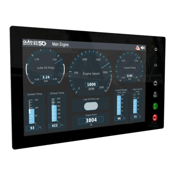
- Page 1 Publication P/N 1500932 Installation Manual Marine Pro Series RP 480i Remote Panel Marine Watch S Series S-ONE Alarm Panel...
-
Page 2: Table Of Contents
4.2.3 Flexible I/O [T5-12] 4.2.4 CAN [T13-15] 2 Ordering Information 4.2.5 Relay [T16-18] 3 Overview 4.2.6 Modbus RTU [T19-21] 3.1 Overview of the Marine Pro Series 4.2.7 HDMI 3.2 Overview of the Marine Watch S Series 4.2.8 USB 3.3 Networking 4.2.9 Ethernet 4.2.10 NMEA 2000... -
Page 3: Preface
1 Preface 1.1 About this Manual This manual has been published primarily for professionals and qualified personnel. The user of this material is assumed to have basic knowledge in marine systems, and must be able to carry out related electrical work. Work on the low-voltage circuit should only be carried out by qualified and experienced personnel. -
Page 4: Ordering Information
2 Ordering Information The Marine Pro and Marine Watch series covers a wide range of compatible products within both the series. Please visit our website for more information. Page 4 (10) -
Page 5: Overview
3 Overview 3.1 Overview of the Marine Pro Series 3.2 Overview of the Marine Watch S Series Typical installation shown below. 3.3 Networking The products use Ethernet as a communication medium. Either connect the products directly, or use Ethernet switches to expand the network. -
Page 6: Installation
4 Installation This chapter covers the installation of the RP 480i and Marine Watch S-ONE panels. 4.1 Mounting Panels with a screen should be mounted so the operator can easily view and operate the panel. Ensure easy access to the rear wiring. Use the included mounting frame. -
Page 7: Screw Torque
Using too long screws will damage the panel. 4.1.3 Screw Torque The threads in the unit are pre-fitted with threadlocker. Use only two fingers on the screwdriver as the image below shows to tighten the screws with a fair torque. Do not over tighten the mounting screws. -
Page 8: Connections & Wiring
4.2 Connections & Wiring Power LED HDMI Supply USB-A (2.0 High-speed interface) +24 V ● USB 1 ● USB 2 Power on ● USB 3 Shield Reserved for software update, event log extraction, and configuration file handling Flexible I/O Ethernet I/O #1 ●... -
Page 9: General
I/O #4 Ethernet 1 is preferred for networking. I/O #5 10. I/O #6 11. I/O #7 12. I/O #8 CAN bus, Relay, Modbus RTU NMEA 2000 – isolated 13. CAN L 14. CAN H 15. CAN 0V 16. Relay NC 17. -
Page 10: Can [T13-15]
4.2.4 CAN [T13-15] Use shielded twisted cables for CAN, where CAN-H and CAN-L are twisted. Connect the shield to one end of the cable only. 4.2.5 Relay [T16-18] The relay has a 0.7 A overcurrent protection on the common pin. See the respective User Manual for relay functionality.
Need help?
Do you have a question about the Marine Pro Series and is the answer not in the manual?
Questions and answers