
Related Manuals for auto maskin Marine Pro 200E Series


Summary of Contents for auto maskin Marine Pro 200E Series
- Page 1 Manual# 1006495 Installation Manual Marine Pro 200E Series DCU 210E/208E – Engine Controller RP 210E/220E/206E – Remote Panel Marine Watch LT Series LT-ONE Main Panel LT-ACE Remote Panel...
- Page 2 Installation Manual for the Marine Pro 200E Series Marine Watch LT Series DCU 210E/208E Engine Controller RP 210E/220E/206E Remote Panel LT-ONE Main Panel LT-ACE Remote Panel Revision Revised November 1, 2019 Revision history: Rev. Date Description 2.9.2015 Initial release. 4.9.2015 Corrected thermistor terminals on page 6.
-
Page 3: Table Of Contents
Table of Content Connector Pinout – DCU 210E/208E and LT- DOCUMENT INFORMATION ........ 1 ONE ..............6 ..........1 BOUT THIS ANUAL Connector Pinout – RP 210E/220E/206E and Responsibilities ..........1 LT-ACE............7 ..........1 ATCHING IRMWARE ..........7 IRING ONNECTIONS ........ -
Page 4: Document Information
Document For updated information, please contact your local distributor. Information Matching Firmware About this Manual This Installation Manual is for the 200E Series and Marine Watch LT Series of This manual has been published panels. primarily for professionals and It has been updated to match the qualified personnel. -
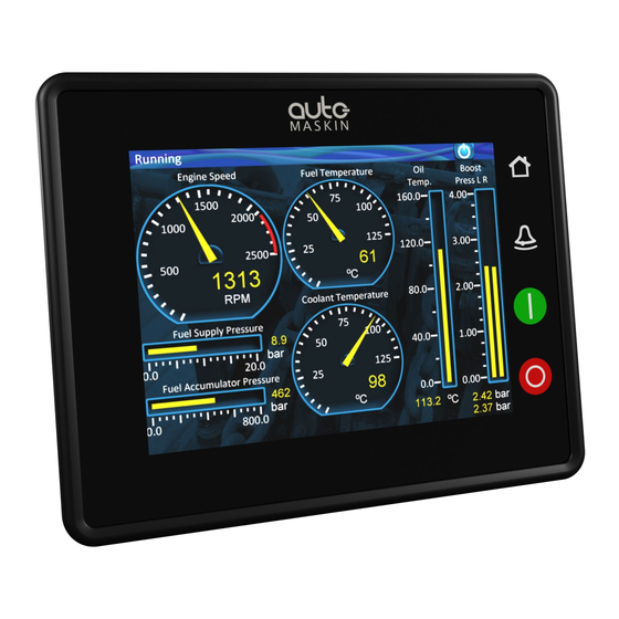
Page 5: Overview Of The 200E Series
Overview of the 200E Series The drawing above shows a typical It saves cost being used in smaller layout. engine rooms, where a remote panel is all that is needed. DCU 210E Engine Controller Configuration The DCU 210E engine controller is the main building block in the 200 Series. -
Page 6: Overview Of The Marine Watch Lt Series
Common As such, the RP can easily be retrofitted. Components The RP also supports one IP-camera to be installed on the network. Ethernet Switch The Ethernet switch is not necessary if Overview of the only two units are in use. These can Marine Watch LT then be wired with an Ethernet cable Series... -
Page 7: Installation
Installation The panel does not have a user interface and is normally used in unmanned engine rooms. Installation covers panel location, A RP 210E/220E/206E remote panel wiring and first power-on. can be used to bring the signals from the engine room to a monitoring site, Panel Location e.g. -
Page 8: Panel Cut-Out
Connectors Panel Cut-out The cut/out size is: These are the connectors on the back 153mm width, 123 mm height lid. Mounting Bracket When installing the panel make sure to use the bundled screws and mounting bracket. If installing the panel on a thicker surface than 5mm, longer flanged screws must be used. -
Page 9: Connector Pinout - Dcu 210E/208E And Lt- One
Connector Pinout – C4.6 Thermistor #1 A C4.7 Thermistor #1 B DCU 210E/208E and LT-ONE C4.8 Thermistor #1 C C4.9 Thermistor #2 A The table below shows the connector C4.10 Thermistor #2 B pinout. C4.11 Thermistor #2 C Flexible I/O C1.1 I/O #1 In/Out... -
Page 10: Connector Pinout - Rp 210E/220E/206E And Lt-Ace
Connector Pinout – Wiring Connections RP 210E/220E/206E and LT- The following chapter primarily assumes a DCU or LT-ONE panel. The table below shows the connector If installing an RP or LT-ACE, then just pinout on the RP panel. disregard descriptions that is not described in the table “Connector The connector is described as e.g. -
Page 11: Power Supply [C1P11 - C1P12]
Power Supply [C1P11 – C1P12] Alarm for Low Power Supply The input voltage is monitored with The panels are designed to run on fixed set points. The set points are as either 12 VDC or 24 VDC supply follows: voltage. Note! Make sure the supply power is 24 V supply sourced directly from the battery, and... -
Page 12: All Faults Relay [C2P1 - C2P3]
All Faults Relay [C2P1 – C2P3] Modbus RS-485 [C4P3 – C4P5] The DCU has an inbuilt Modbus™ Note that the relay is activated when there are no faults, and deactivates for interface, both on RS-485 and also on any fault. Ethernet. -
Page 13: Other Interfaces
Power Output Each channel can be configured as an engine switch, e.g. Oil Pressure Low All flexible I/O can be configured as switch, or it can be configured to 12V 0,2A or 24V 0,2A power outputs activate an inbuilt function, eg. with short circuit detection and Automatic Start. -
Page 14: Power -O N
Update the panel firmware (all panels) Copy a valid configuration and/or firmware file to a USB memory stick, and insert the USB memory stick in the panel. Follow the instructions that will be appearing on the screen. First Power-On Preparations First, make sure to consult the Quick Installation Guide (QIG) that came with... -
Page 15: Typical Sensor Connections Dcu 210E
Appendix A T y p ic al s en so r c on n ec ti on s D CU 2 1 0 E Installation Manual – 200E Series and Marine Watch LT Series Page 12...
Need help?
Do you have a question about the Marine Pro 200E Series and is the answer not in the manual?
Questions and answers