auto maskin Marine Pro 400 Series Installation Manual
Hide thumbs
Also See for Marine Pro 400 Series:
- Configuration manual (99 pages) ,
- User manual (10 pages) ,
- Installation manual (7 pages)

Related Manuals for auto maskin Marine Pro 400 Series


Summary of Contents for auto maskin Marine Pro 400 Series
- Page 1 Publication P/N 1100413 Installation Manual 400 Series SDU 404 Safety Shutdown Unit, P/N 1006418 SDU 420 Safety Shutdown Unit, P/N 1500158...
-
Page 2: Table Of Contents
Table of contents 1 Preface 1.1 About this Manual 1.2 Responsibilities 1.3 Revisions 2 Ordering Information 3 System Overview 3.1 DCU Engine Controller 3.2 RP Remote Panel 3.3 Ethernet Switch 4 Installation 4.1 General 4.1.1 LED Overview 4.2 Wiring 4.2.1 DC Supply 4.2.2 Switch Channels 4.2.2.1 Broken Wire Detection 4.2.2.2 Short Circuit Detection... -
Page 3: Preface
1 Preface 1.1 About this Manual This manual has been published primarily for professionals and qualified personnel. The user of this material is assumed to have basic knowledge in marine systems, and must be able to carry out related electrical work. Work on the low-voltage circuit should only be carried out by qualified and experienced personnel. -
Page 4: System Overview
3 System Overview The figure below shows a typical layout with the SDU included for one engine. 3.1 DCU Engine Controller The DCU Engine Controller is the main building block in the Marine Pro family. Engine sensor values are displayed on the colour touch screen, and commands and other user interaction is also here. -
Page 5: Installation
4 Installation This chapter covers the installation of the SDU 404 and SDU 420. 4.1 General The SDU 404 and SDU 420 are engine safety modules. They are primarily designed to be used together with the Marine Pro family, although stand-alone operation is possible. They can be installed separate from the DCU or in the same cabinet. - Page 6 Color Description Power Green Steady lit when power supply is OK. Flashing when below the configurable “very low threshold”. Running Green Steady lit when the engine is running. Overspeed Flashing when unacknowledged overspeed. Steady lit when acknowledged overspeed. Green Test mode Shutdown Flashing when unacknowledged shutdown.
-
Page 7: Wiring
Steady lit when acknowledged fault. Green Active. Shutdown Override Switch Amber Flashing when unacknowledged fault. Steady lit when acknowledged fault. Green Active. SW 1-12 Flashing when unacknowledged shutdown/load reduction. Steady lit when acknowledged shutdown/load reduction. Amber Flashing when unacknowledged fault. Steady lit when acknowledged fault. -
Page 8: Broken Wire Detection
4.2.2.1 Broken Wire Detection Requirement for type approved installations. Each switch shall have a 10 kΩ resistor connected across. The 10 kΩ resistors shall be connected directly at the switch, and not at the SDU. Switches shall be normally open (NO), and shall close to indicate engine shutdown. 4.2.2.2 Short Circuit Detection Each switch shall have a 10 kΩ... -
Page 9: Pickup Channel
4.2.4 Pickup Channel The SDU can operate with a magnetic or active pickup source. In case of an active pickup source, the SDU needs to be configured properly. Connect the pickup to terminals 4 and 5, with shield to terminal 3. Make sure the cable shield is connected at the SDU side and not at the pickup side. -
Page 10: Connection Parameters
If there are several units attached to the link then connect the 120 ohm resistor together with the last unit on the bus only. 4.3.1 Connection Parameters The two-wire SDU Link has fixed communication parameters. The Baud rate is 19200 baud. ●... -
Page 11: Buttons
4.4 Buttons 4.4.1 Acknowledge This button is used to acknowledge alarms and faults. See User’s Manual for more details. 4.4.2 Overspeed Test Press and hold the “Overspeed Test” button for more than two seconds to enter the overspeed test mode. See User’s Manual for more details. 5 Configuration 5.1 Configure SDU using the DCU The recommended method of configuring the SDU is to login to the DCU via the web... -
Page 12: Analog
Type Select the type of short circuit and broken wire detection. Type 1: Short circuit and broken wire detection. A 10 kΩ resistor to be connected in series and a 10 kΩ resistor to be connected in parallel over the switch. Type 2: Broken wire detection. -
Page 13: Miscellaneous
Select the event (Shutdown and/or Load Reduction) that will be activated when the switch is closed. Sensor Min / Sensor Max Defines the sensor value at 4 mA and 20 mA. Load Reduction Threshold and Type Set the threshold value and threshold type. Shutdown Threshold and Type Set the threshold value and threshold type. -
Page 14: Output Functions
5.1.6 Output Functions Configuration of relays and digital output. 5.1.7 Synchronize Synchronization of DCU and SDU configuration. 6 Appendix A - Wiring The diagram below shows recommended wiring for SDU 404 including 3 different types of Switch inputs. The SDU 420 is similar to this diagram. Page 14 (15) -
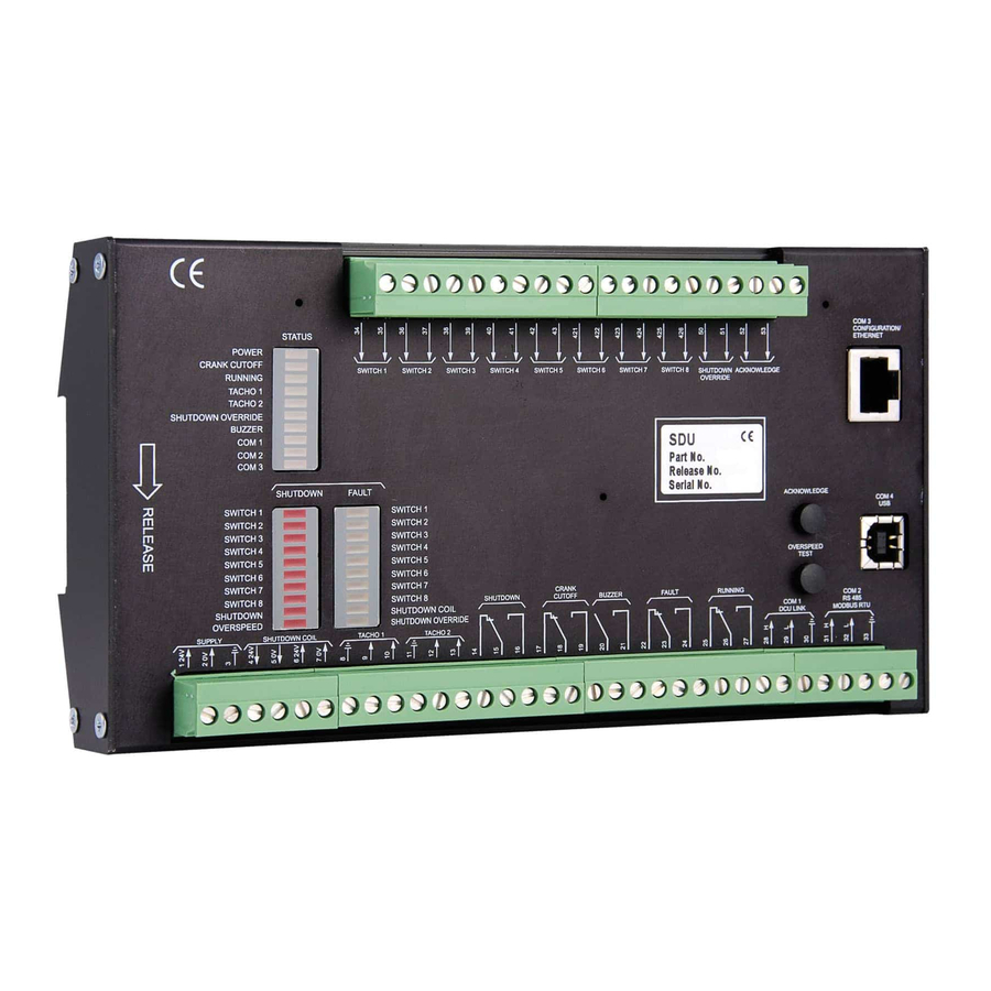
Page 15: Appendix B - Front & Back
7 Appendix B - Front & Back Page 15 (15)
Need help?
Do you have a question about the Marine Pro 400 Series and is the answer not in the manual?
Questions and answers