
Related Manuals for auto maskin S Series


Summary of Contents for auto maskin S Series
- Page 1 Publication P/N 1050161 User Manual Marine Watch S Series S-ONE Alarm Panel S-ACE Annunciator Panel I/O Cabinet...
-
Page 2: Table Of Contents
Table of content 4.2.4 Grouped Channels 1 About this Manual 4.2.5 Buzzer 1.1 Intended Audience 4.3 Display 1.2 Responsibilities 4.3.1 Brightness 1.3 Revisions 4.3.2 Mode 1.3.1 Software revisions 4.3.3 Theme 1.3.2 User Manual Revision 4.3.4 Sparkline 2 System Overview 4.3.5 Screensaver 2.1 Introduction to Marine Watch 4.3.6 Clean Screen 2.2 Typical Installation... - Page 3 6.1 Buttons 7.1.1 Ground 6.2 Header Information 7.2 Ethernet Communication 6.3 Header Status Symbols 7.3 Switch Channels 6.4 Alarm View 7.4 Analog Channels 6.5 Menu 7.5 Output Channels 6.5.1 Main Menu 7.5.1 Standard Output Channels 6.5.2 Administration Menu 7.5.2 Expansion Output Channels 7.6 Alarm Panel Supply 7 I/O Cabinet Connections 7.1 Power Supply...
-
Page 4: About This Manual
1.3 Revisions This manual is valid for the latest software version of the Marine Watch S Series Alarm Panel. 1.3.1 Software revisions ● See this document for S-ONE Alarm Panel software revisions. -
Page 5: System Overview
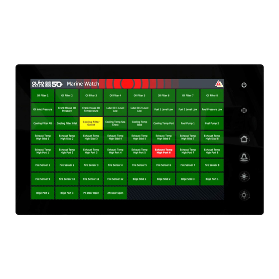
2 System Overview 2.1 Introduction to Marine Watch The Marine Watch S Series is a sophisticated and powerful alarm system, designed to be easy to set up and use. The S-ONE Alarm Panel touch screen displays binary events as rectangles, where each rectangle represents the status of a channel. -
Page 6: Components And Default Ip Address
2.3 Components and Default IP Address All Marine Watch S Series’ components have a factory-default IP address. If more than one of each type of component is in use, then make sure to change the IP address of the extra component. -
Page 7: Annunciator Panels
2.3.1 Annunciator Panels Several S-ACE annunciator panels can be added in the network. An annunciator panel is automatically always in sync with the S-ONE Main Panel configuration. Default IP address: 192.168.0.201 2.3.2 I/O Cabinet The I/O Cabinet is the sensor hub. It collects all sensor data and makes it available to the Marine Watch Panels. -
Page 8: S-One Alarm Panel
2.5 S-ONE Alarm Panel 2.5.1 Connectivity and Interfaces The rear underside of the S-ONE Alarm Panel has all the interfaces. Power LED HDMI Power supply USB-A (2.0 High-speed interface) +12/24 V ● USB 1 ● USB 2 Power on ● USB 3 Reserved for software update, event log extraction, and configuration file handling... -
Page 9: Operator Interface
Miscellaneous Buzzer Activates for any new event. Ambient Light Sensor Automatic adjustment of screen brightness. Proximity Sensor Motion detection. 2.5.2 Operator Interface In addition to the touch interface on the screen, there are buttons on the right-hand side of the panel. These are used to control different parts of the panel as described below: Interface Power Indication Lit when the panel is powered. -
Page 10: S-Ace Annunciator Panel
2.6 S-ACE Annunciator Panel 2.6.1 Hardware Connections Connectivity Description Connector Power C1.11: +12/24 V Typical: 0.4 A @ 24 V C1.12: 0 V External Buzzer C1.1 Max: 0.2 A 0 V at C1.12 or other 0 V. Ethernet RJ 45 USB-A For full information of the connectivity and interfaces, see the datasheet of the product. -
Page 11: Periodically Unattended Engine Room
Optional operator-controlled expansion outputs can be added to the I/O Cabinet. 2.8 Periodically Unattended Engine Room The Marine Watch S Series system supports periodically unattended engine room installations. The minimum setup for a periodically unattended engine room installation is the following ●... - Page 12 Watch Responsibility Indication The following symbol is shown in the panel header when the panel has watch responsibility. If the engine room has watch responsibility, this is equivalent to an attended engine room. Likewise, if the bridge has watch responsibility, the engine room can be unattended. In addition, engine room status (attended / unattended) as well as on-duty engineer (in case of unattended engine room) can be inspected using the panel menu.
- Page 13 Select which “Engineers Cabin” shall be “On duty”. If no Engineers Cabin panel exists in the system, this is indicated with a popup and the transfer request is aborted. Audible sound and dialog on all Bridge panels. If the bridge accepts the transfer, watch transfer is performed, and the bridge has the watch responsibility.
-
Page 14: Buzzer And Acknowledge
Activate buzzer Activate buzzer The Marine Watch S Series panels installed on the bridge can be configured to which channel groups shall activate the buzzer in an attended engine room situation. This can be used to minimize the potential disturbance on the bridge when the engine room is attended. -
Page 15: Engineers Alarm
Engine Room / Engine Control Room The S-ONE Main Panel should be configured to acknowledge all events. If an S-ONE Subpanel is installed in the engine room, in addition to the S-ONE Main Panel, it can be configured to acknowledge events as well as performing a system-wide silence. Silencing the buzzer on one of these panels will silence all buzzers in the Marine Watch S Series system. -
Page 16: The S-One User Interface
3 The S-ONE User Interface 3.1 Header Information The header consists of the following information. ■ The logotype, if any. This can be changed in the configuration. ■ The default panel name is Marine Watch. The name can be changed in the configuration. -
Page 17: The Switch Channel Page
3.2 The Switch Channel Page There will be one or several pages with rectangles. This is dependent on the configuration, the number of connected I/O Cabinets, and the type of I/O in each Cabinet. Each rectangle represents the status of one switch input channel, and each page can display status from up to 60 channels. -
Page 18: Channel Status
3.2.1 Channel Status Each rectangle represents the status of a binary channel as follows. Status Description Sample Graphic Representation Normal The channel is not alarming. Active and not The channel is acknowledged alarming, following its persistence timer. Text in bold, flashing. Active and The channel is acknowledged... -
Page 19: The Analog Channel Page
3.3 The Analog Channel Page The analog page can display up to eight channels in a 4 x 2 grid. Each channel is represented as a circular gauge or as a bar graph widget. An optional Sparkline can be displayed. A maximum of two analog pages can be displayed, holding a maximum of 16 analog channels. -
Page 20: Channel Status
3.3.1 Channel Status Status Description Sample Graphic Representation Normal The channel is not alarming. Active and not The channel is alarming, acknowledged following its persistence timer. Instrument text in bold, flashing. Active and The channel is acknowledged acknowledged by an operator and will clear when the alarm clears. - Page 21 Status Description Sample Graphic Representation Disabled The channel has been disabled by an operator. Disabled, but The channel has been active event disabled by an operator and is indicating an event. Page 21 (65)
-
Page 22: The Output Channel Page
3.4 The Output Channel Page The panel can be configured to display up to 16 operator switches on one page. Note that the I/O Cabinet must have the optional expansion output modules. The output channels can be configured to either toggle or momentary. Only the Main Panel can control the outputs. -
Page 23: The S-One Main Menu
4 The S-ONE Main Menu The Main Menu is always available to the operator. It is divided into several sections as follows. 4.1 Attendance The Attendance menu is available only if any of the following has been configured ● Periodically Unattended Engine Room (enables the Engine Room section) ●... -
Page 24: Engineers Call
A panel I/O output can be configured to indicate dead man reminder, and a panel I/O input can be configured to reset the dead man alarm timer. 4.1.3 Engineers Call The engineer in the engine room or engine control room can request assistance from any other panel in the Marine Watch S system. -
Page 25: Home Page
4.2.3 Home Page The Home Page is an optional overview of all the pages and makes it easy to navigate to any page from here. Events are summarized per page, and disabled channels are indicated. The Home Page is divided into three rows: ●... -
Page 26: Buzzer
4.2.5 Buzzer The panel buzzer volume can be configured in the administrative part of the menu. Panel Buzzer Pattern Standard Standard on / off pattern. Annoying Four quick beeps. Touch Feedback Silenced. 50 % volume. Normal 100 % volume. Event Count in Header The event count per severity can be configured to be displayed in the header. -
Page 27: Display
4.3 Display Various display settings are controlled from here. 4.3.1 Brightness Brightness Manually adjust the backlight brightness (0-100%). Brightness slider The backlight brightness is adjusted automatically. Auto Note! Using the physical buttons to change the brightness will set Auto to Off. -
Page 28: Theme
4.3.3 Theme Theme Day Mode Choose a color representation for use in Day mode Night Mode Choose a color representation for use in Night mode Disabled channels can be configured to be displayed in black & white. 4.3.4 Sparkline A Sparkline is a miniature chart contained within the circular gauge and bar graph. Choose between 30 or 60 minutes of history, and a line or area representation. -
Page 29: Clean Screen
4.3.6 Clean Screen Clean Screen Clean Screen Displays the screen in all-black so fingerprints are clearly visible and can be wiped off with a soft cloth. Press the button on the screen to exit. 4.4 Event Log The event log is displayed in chronological order. The Event Log holds the last 1000 events and can be exported as a CSV file to a USB storage device. -
Page 30: Troubleshooting
Legend Indication An Alarm event. A Warning event. Configuration change. Information. 4.5 Troubleshooting The Troubleshooting menu can be used to help to diagnose faults. 4.5.1 This Panel Troubleshooting this panel. Indication Supply Voltage The panel supply voltage is displayed. Buttons Buzzer Test Press and hold the button to activate the buzzer. -
Page 31: System Status
Button Test The button brings up a dialogue for testing of the panel's physical buttons. 4.5.2 System Status The active internal events, if any, are listed here. Unacknowledged events are listed in bold. Press the corresponding Acknowledge button to acknowledge the event. The following internal events are defined. -
Page 32: Subpanel
Communication Connection state Connectivity status between the Main Panel and the I/O Cabinet. Connection attempts Connection attempts since the last restart of this panel. Successful Number of successful connections since the last restart. connections Transmitted packets Data packets transmitted. Received packets Data packets received. -
Page 33: I/O Cabinet
4.6.1 This Panel This section lists the panel settings. 4.6.1 I/O Cabinet This section lists the I/O Cabinets in use. Each I/O Cabinet lists the IP address and the I/O Cabinet capacity. 4.6.2 Administration Menu This login button is the entrance to the Administration Menu. To log in, press the Log In button, then add the following info into the dialogue. - Page 34 Three failed PIN code attempts will result in a PIN code lockout for 5 minutes, and also an encrypted PIN code. If the PIN Code is lost, then your distributor can source the PIN code using the encrypted PIN code. The following buttons can appear.
-
Page 35: The S-One Administration Menu
5 The S-ONE Administration Menu All the configuration is performed in the varying sub-sections of the Administration Menu. Any configuration change is saved in the Alarm Panel as soon as it is entered. 5.1 This Panel This section holds the top-level configuration of this panel. The page is scrollable. -
Page 36: Panel Location
There shall be only one Main Panel in a network. Having multiple Main Panels connected to the same I/O Cabinet can cause unpredictable behavior. 5.1.3 Panel Location Select a location for this panel. The panel location is used for the following functions ●... -
Page 37: Timestamped Events
This is required to fulfill sound requirements in a type approved installation. 5.1.5 Timestamped Events Configures the source to use for the timestamping of events. Buttons Internal The panel uses the internal real-time clock. External The panel reads data from an external time-server. This software release does not support external time sources. -
Page 38: Panel I/O
Acknowledge Button Nothing No action. Ack. Page Acknowledges all events visible on this page. Ack. All Acknowledges all events. System-wide Buzzer Silence Configures the behavior of the buzzer in the entire system. This setting is only present for Subpanels. System-wide Buzzer Silence Enabled Silences the buzzer on all panels in the system. - Page 39 Input Functions Silence Buzzer Silences the panel buzzer. Reset Dead Man Alarm Resets the Dead Man Alarm timer. Output Functions Buzzer Active Active when the panel buzzer is active. Note that the panel buzzer can be disabled, but this does not affect this function. Unacknowledged Events Active for any unacknowledged events.
-
Page 40: System
5.2 System System settings for the Marine Watch S system. If the panel is configured as a Subpanel, the Main Panel IP address shall be configured, and not the I/O Cabinet. 5.2.1 I/O Cabinet Network Set the IP address of the I/O Cabinet in the network. The default IP address for an I/O cabinet is 192.168.0.11. -
Page 41: System Setup
I/O Cabinet IP address I/O Cabinet 1 (default) 192.168.0.11 I/O Cabinet 2 192.168.0.12 I/O Cabinet 3 192.168.0.13 I/O Cabinet 4 192.168.0.14 Make sure to reboot the I/O Cabinet after any changes to the S1 or S2 rotary switches. Type Select the correct I/O Cabinet type from the range of supported I/O Cabinets. This menu option is available only if the panel is configured to be the Main Panel. -
Page 42: Panels In The System
The S-ONE needs to have Internet access, and the Gateway setting under This Panel must be correctly configured. For more information on the Broadcast, please see the Marine Watch Broadcast User Manual. 5.2.3 Panels in the System Select the panels to be monitored in the Marine Watch S system. Selected panels can be named, and the system will issue warnings if the communication to the panel is lost. -
Page 43: Analog Channels
Type Press the channel number to enable or disable that channel. Channel Description The text displayed in the rectangle. Maximum 45 characters and four lines of text; word wrapping is performed automatically. Condition Any condition which must be fulfilled in order for this channel to issue an event. -
Page 44: Output Channels
The configuration for each analog channel is as follows. Type Press the channel number to enable or disable that channel. Description The text displayed in the circular gauge or bar graph. Maximum 45 characters and four lines of text; word wrapping is performed automatically. - Page 45 Available Functions Buzzer Active Activates on any new events. Deactivates on – acknowledge of event, OR – press the Alarm button Unacknowledged Events Active if at least one unacknowledged event is present. Active or Unacknowledged Events Active if at least one active OR at least one unacknowledged event is present.
- Page 46 Available Functions Unacknowledged Events in Group 1 Active if at least one unacknowledged event in group 1. Unacknowledged Events in Group 2 Active if at least one unacknowledged event in group 2. Unacknowledged Events in Group 3 Active if at least one unacknowledged event in group 3.
-
Page 47: Expansion Output Channels
5.5.2 Expansion Output Channels Expansion output channels are reserved for operator commands that are displayed on a separate page. Type Press the channel number to enable or disable that channel. Description The text displayed in the circular gauge or bar graph. Maximum 45 characters and four lines of text;... -
Page 48: Group Channels
5.6 Group Channels An Alarm Panel can have the authority to acknowledge all channels or a select group of channels only. Channels are by default not assigned to any group but can be assigned to any of the three available groups. All Alarm Panels in a network can acknowledge unassigned channels. To edit this, the panel must be a Main Panel. -
Page 49: Conditions
5.7 Conditions Configure up to 10 conditions which can be used in channel configuration. If used in channel configuration, the condition must be fulfilled for the channel to issue an event. Page 49 (65) -
Page 50: Maintenance
5.8 Maintenance 5.8.1 Security Change PIN Code Dialogue for changing the active PIN code for logging in to the Administration menu. SSH Server Enables a debug SSH server for this panel. A power cycle will disable the SSH server again. Page 50 (65) -
Page 51: Panel Maintenance
5.8.2 Panel Maintenance Date & Time Sets the date and time of the panel. Factory Reset A Factory Reset will remove and reset the following ■ Configuration ■ Event log ■ User PIN code Software Update Updates the software of the Alarm Panel. Using any of the 3 available USB-A ports, insert a USB storage device with a software update file, marine-watch-image.mender, and press the Software Update button to start the update. -
Page 52: Logo
A saved configuration file will be named config.ini and overwrite any current file on the USB storage device. 5.8.4 Logo Select which logo, if any, should be presented in the header. Logo Standard The default logo. Custom The custom logo, which can be changed. None No logo in header. -
Page 53: The S-Ace Annunciator Panel
6 The S-ACE Annunciator Panel The S-ACE Annunciator Panel displays the events from the S-ONE Main Panel in an Alarm View. No configuration is required, other than the network configuration. The S-ACE can be configured to show all events, or a subset of the events available in the S-ONE Main Panel, based upon group settings. -
Page 54: Header Status Symbols
6.3 Header Status Symbols These symbols may appear in the header bar. At least one channel At least one channel At least one Alarm and At least one new indicate Alarm indicate Warning at least one Warning Alarm or Warning The buzzer is disabled Watch responsible by the operator... -
Page 55: Menu
Events All OK Communication Failure Channel Status Each rectangle represents the status of a channel as follows. Status Description Sample Graphic Representation Active and not The channel is acknowledged alarming, following its persistence timer. Text in bold, flashing. Active and The channel is acknowledged acknowledged by an... -
Page 56: Main Menu
6.5.1 Main Menu Quick Controls Whenever the Main Menu is accessed, it always displays the Quick Controls section. These settings are used most frequently. Page 56 (65) - Page 57 Display Brightness Low, Medium, High Select the screen brightness Mode Colors optimized for daylight. Night Colors optimized for use in dark environments. Clean Screen Clean Screen Displays the screen in all-black so fingerprints are clearly visible and can be wiped off with a soft cloth. Press the button on the screen to exit.
- Page 58 Administration This is the login page for the Administration menu. It also displays some data as follows. This button is the entrance to the Administration Menu. To log in, press the Log In button, then add the following info into the dialogue. ■...
-
Page 59: Administration Menu
6.5.2 Administration Menu This Panel Network Set the IP address of this S-ACE panel. Make sure all IP-addresses in the network are unique. Panel Buzzer Enable / disable the panel buzzer for any new event. It is possible to connect an external buzzer to the panel using connector C1.1. This is required to fulfill sound requirements in a type approved installation. - Page 60 Main Panel Network Set the IP address of the S-ONE Main Panel. Page 60 (65)
- Page 61 System Panel Location Select the panel location. Buzzer when Attended Engine Room If the Bridge panel location is selected, and Periodically Unattended Engine Room is enabled for the Marine Watch S system, the panel can be configured for which groups the buzzer shall be enabled for new events.
- Page 62 Maintenance Change PIN Dialogue for changing the active PIN code for logging in to the Administration menu. Factory Reset A Factory Reset will remove and reset the following ■ Configuration ■ User PIN code Software Update Updates the software of the Annunciator Panel. Insert a USB storage device with a software update file, marinewatch_sace.tar.gz, and press the Software Update button to start the update.
-
Page 63: O Cabinet Connections
7 I/O Cabinet Connections All references below are made to the I/O Cabinet wiring diagram. Always refer to the supplied wiring diagram for details. In case of conflicting information in the wiring diagram and this manual, then follow the wiring diagram. 7.1 Power Supply The I/O Cabinet supports dual power supplies. -
Page 64: Analog Channels
7.4 Analog Channels All analog input channels shall be connected directly to the I/O module. Connect either a 4-20 mA signal or a 0-10 V signal per channel. From the wiring diagram, locate the correct I/O module and connect as follows. Analog channel 0-10 V 4-20 mA... -
Page 65: Expansion Output Channels
7.5.2 Expansion Output Channels All switch output channels shall be connected directly to the I/O module. From the wiring diagram, locate the correct I/O module and connect as follows. Switch output channel Connections 00 – 10 01 – 11 02 – 12 etc.
Need help?
Do you have a question about the S Series and is the answer not in the manual?
Questions and answers