Table of Contents
Advertisement
Quick Links
Advertisement
Table of Contents

Related Manuals for Acclaim Lighting Unity SNS2019


Summary of Contents for Acclaim Lighting Unity SNS2019
- Page 1 Unity™ User guide...
-
Page 3: Table Of Contents
CONTEN TS IN TR OD UC T ION ........3 Welcome Safety, maintenance and cleaning Supplied items Optional extras Outdoor Linking System part codes IN STA L L ATIO N ......... . 8 Mounting the unit Using a tenon mount Using a pipe clamp... - Page 4 F UR T H E R IN FOR M ATI O N ......4 3 Troubleshooting Correlated color temperature selection Optimizing signal strength via channel selection Choosing the right location Specifications Dimensions FCC approval Limited product warranty...
-
Page 5: In Tr Od Uc T Ion
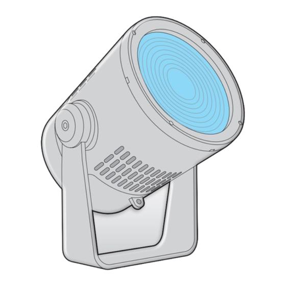
I NT ROD UC TI ON WELCOME Welcome to Unity™ from Acclaim Lighting. This rugged fixture brings new levels of flexibility, performance and refinement to exterior illumination. The Spectrum Five light engine (red, green, blue, amber and lime) offers exceptional brightness and clarity. -
Page 6: Supplied Items
S U P PL I ED IT E MS Unity Supplied with integral mounting yoke and detachable 9 foot (2.7m) combined power and control tail. Optional Outdoor Linking System feed cables are directly compatible - see page 7. O P T I ON A L EXT R AS Half snoots Gray [UNAHSG]... - Page 7 OPTIONAL EX TR AS (CO N TI N U E D) Tenon mounts For use with Schedule 40 pipe: 2.51” and 4.13” inner diameter respectively. 2” pole 4” pole Gray [TM2G] [TM4G] Black [TM2B] [TM4B] White [TM2W] [TM4W] Custom* [TM2C] [TM4C] * RAL # also required Pipe clamps...
- Page 8 OPTIONAL EXT R AS (CO N TI N U E D) Pendant mount set Includes ceiling mount and replacement fixture yoke. NPS pipe required (see below). Gray [UNAPMSG] Black [UNAPMSB] White [UNAPMSW] Custom* [UNAPMSC] * RAL # also required NPS pipe One length required to accompany a pendant mount set (1”...
-
Page 9: Outdoor Linking System Part Codes
OU T D O OR LI NKIN G SYSTE M PART CODE S T-junction [OLST] Feed cables 1’ (30cm) [OLSF1] 5’ (1.5m) [OLSF5] 10’ (3m) [OLSF10] 25’ (7.6m) [OLSF25] 50’ (15.2m) [OLSF50] Link cables 1’ (30cm) [OLSL1] 5’ (1.5m) [OLSL5] 10’... -
Page 10: I Nsta Ll Ati On
I NSTA LL ATI ON MOUNTING T H E UNIT Each Unity fixture includes a sturdy yoke mount with multiple holes in its base for various fixing options. The Unity fixture weighs 26.9 lbs (12.2 kg) - ensure that the mounting surface and the fixings used are sufficiently rated for the task (including wind shear forces). -
Page 11: Using A Tenon Mount
USING A TENON MO U NT Optional tenon mounts are available for use when Unity needs to be mounted on top of a vertical pole. Tenon mounts are available for use with 2” and 4” (Schedule 40) poles of sufficient rigidity for the weight of the fixture. IMPORTANT: Tenon mounts are Main bolt... -
Page 12: Using A Pipe Clamp
USI NG A PIPE CL AM P Optional pipe clamps are available to mount Unity fixtures on either 2” (50mm) or 4” (100mm) (Schedule 40) tubes and poles. IMPORTANT: Ensure the pipe (Schedule 40) and its mountings have sufficient load capacity for the Unity fixture(s) to be mounted. -
Page 13: Using An Extender Bar
US I N G A N EX TE NDE R BA R Optional extender bars in various lengths (see page 5 for part numbers and page 50 for dimensions) are available to allow each Unity fixture to be held a certain distance from a vertical mounting surface. -
Page 14: Fitting A Pendant Mount Set
FI T T I N G A PEN DA N T MO U NT S ET IMPORTANT: The pendant mount requires a solid, weight-bearing horizontal mounting surface. You also need to source mounting hardware appropriate to the mounting surface, rated to safely hold the weight of the total fixture plus safety factor. - Page 15 4 Attach the new pendant yoke to the Unity fixture body: • Place the new pendant yoke over the Unity fixture body and gently pull the arms of the yoke out a little so that the pivot cups can correctly mesh with the corresponding pivots of the fixture.
- Page 16 6 Attach the pendant assembly (the NPS pipe, pendant yoke and Unity fixture) to the top bracket. • With assistance from a co-worker, lift up the pendant assembly to the top bracket. • Carefully engage the screw thread of the NPS pipe with the top bracket and rotate the pendant assembly clockwise to fully engage the thread.
-
Page 17: Fitting An Aircraft Cable Mount Set
F I TTING AN AI R CR A F T C ABL E MO U NT S E T IMPORTANT: The aircraft cable mount requires a solid, weight-bearing horizontal mounting surface. You also need to source mounting hardware appropriate to the mounting surface, rated to safely hold the weight of the total fixture plus safety factor. - Page 18 4 Attach the top bracket securely to the ceiling: • Use two fixings (appropriate for the weight of the Unity fixture and the mounting surface) to securely attach the top bracket. • Note: If the power cord is to be fed up through the top bracket, first drill a hole in the mounting surface that will align with the cord hole within the top bracket.
- Page 19 6 Complete the installation: • Feed the power/control cord up through the rectangular hole in the cover plate, through the cord hole in the top bracket and into the ceiling space. • Raise up the cover plate and align it with the two small holes in the underside of the top bracket.
-
Page 20: Fitting A Snoot
Snoots help to reduce or eliminate light spill into unwanted areas. The full and half snoots available from Acclaim Lighting are attached to the Unity fixture in the same way. Tip: Adding a snoot is made easier when the fixture’ s front face is pointing vertically upwards. -
Page 21: Power Cabling
POWER C ABLI NG The supplied combined power and control cord (roughly 9 feet, 2.7m in length and with bare wire tails) attaches to the rear of the fixture via an IP66-rated composite connector. If you need to connect Unity to an Outdoor Link System configuration, use an optional OLS Link Cable (see pages 7 and 23) in place of the included bare wire feed cable. -
Page 22: Wired Dmx Control
WI RED DMX CONT R O L When connecting multiple fixtures (not using the Outdoor Linking System) connect the DMX output of the controlling device to the input wires of the first fixture and feed the output of that fixture to the next. The final fixture in the line should have a 120Ω terminating resistor connected between its DMX + (red/white) and DMX –... -
Page 23: Input Wiring Protection (Ajbox1)
The Acclaim Lighting the AJBOX1. AJBOX1 is an IP66-rated junction box which provides separated AC power and DMX control... - Page 24 A JB OX 1 F EED C ABL E P R EP The AJBOX1 is quite compact considering the number of connections required within it. For best results we recommend that you prepare all cables in the manner shown here in order to provide just enough flexibility without filling the box with excess cable.
-
Page 25: Cabling With Ols
C ABLING W IT H OLS OUTDOORLINK Unity fixtures are directly compatible with the Outdoor Link System. OLS greatly simplifies the task of S Y S T E M distributing power and control to multiple fixtures. OLS is a collection of feed and link cables (of various lengths) plus a T-junction and a terminator, all utilizing IP67-rated connectors together with robust all-weather construction. - Page 26 T YP IC A L OLS CO N FI GUR AT ION (see page 21) The total length from a A terminator must Maximum fixtures and cable T-junction to a fixture be fitted to the lengths in a single OLS run: must not exceed 10’...
-
Page 27: Wireless Dmx Control
WI RELESS D MX CONTR O L The embedded Aria™ wireless system allows you to control any number of Unity fixtures that are within range of an Aria transmitter set to use the same wireless channel: Notes: Optional Aria The wireless DMX channel is totally transmitter independent of the DMX address. -
Page 28: Con Figu R Ati On
CON FIGU R ATI ON RE MOVING THE DI SPL AY COV E R The user display and control buttons are protected behind a removable cover on the rear panel of the Unity fixture. TO REMOV E THE DISPL AY COVER •... -
Page 29: Menu Navigation
ME N U N AV I GATIO N Once you have entered the menu you can use the four control buttons to navigate around the menu and alter settings as necessary. The next page lists the main menu items. Use the arrow 7 second buttons to press to... - Page 30 MAIN MENU ITEMS Sets the DMX start address for this fixture. Depending on the channel mode, either five or seven DMX channels are required. See page 29. Determines whether 5 or 7 (default) DMX channels are required to control the fixture. See page 30. Determines how the fixture should behave when there is no external control input.
-
Page 31: Setting The Dmx Address
SETTI NG TH E DM X ADDR E SS When external control (wired or wireless) is used, the DMX start address of the fixture needs to match the start address being used by the controlling device. Unity uses either five or seven DMX channels (depending on the chosen channel mode - see page 30), beginning with the one chosen here. -
Page 32: Selecting The Channel Mode
SELEC TING TH E C H AN NE L MO DE Unity provides two different channel modes to determine how received DMX input values are mapped to the various emitter colors. Note: The channel mode can also be configured via RDM, see page 38. 7 C HANN EL Allows you to control the five emitter colors individually or alternatively to choose a particular color temperature of white. -
Page 33: Determining Solo Behavior
D ETER MININ G SOLO BE HAV IOR You can choose how the fixture should behave when it is running solo, either because an external control input is not being used at all or because a connection has been temporarily lost. -
Page 34: Color Calibration
USI NG THE AUTO MATIO N F E ATU RE S (PH OTO CELL ) The fixture includes two related features which allow you to automate standalone operation: • The built-in photocell can trigger a pre-mixed color/white output when the ambient light conditions fall below a pre-determined level. -
Page 35: Adjusting The Gamma Setting
ADJUSTING TH E GAM M A S E TTING Like most light sources, the manner in which LED emitters operate means they exhibit a non-linear response. This means that to achieve changes in output levels which look proportional and correct to the eye (particularly on camera), it is necessary to vary the rate of change at the lower and upper ends of the dimming range in... -
Page 36: Changing The Display Settings
CH ANGING T HE DI SP L AY S E TTIN GS This option contains four settings related directly to the user display: • Invert - allows you to invert the text on the user display so that it reads correctly when the fixture is mounted upside-down. -
Page 37: Running A System Test
SETTI NG A WH IT E BA L ANC E White balance is a legacy feature from Acclaim Lighting Dyna Drum fixtures which allows you to ‘bias’ particular colors so that when the R, G, B, A and L channels are all brought up, your pre-programmed bias will achieve a desired shade of white. -
Page 38: Configuring Aria Wireless Dmx
CONFIGURING A RI A WIR E L E SS DM X Each Unity fixture includes an internal Aria™ wireless DMX receiver unit to allow it to be remotely controlled by an Acclaim Lighting Aria transmitter. Fifteen radio channels are available to choose... -
Page 39: Unity Configuration Via Rdm
• Set the solo behavior - see page 41, • Test the emitter outputs - see page 42. Various third party DMX/RDM tools are available; Acclaim Lighting recommends the XMT-350. CO NFIGU RING THE DMX ADD RESS VI A RDM When external control (wired or wireless) is used, the DMX start address of the fixture needs to match the start address being used by the controlling device. - Page 40 SET TING TH E CHAN NEL MOD E VIA RDM For general information about the channel modes, see page 30. TO SET THE CHANNEL MODE USING THE XMT-350 1 Connect the XMT-350 to the DMX input line of the Unity installation. 2 On the XMT-350, press the button, then use the arrow buttons to highlight the MODE...
- Page 41 SE TTING THE W IRELE SS CHA NNE L VI A R DM For general information about using wireless control, see page 25. For details about choosing channels and locations, see page 45. Note: Although Aria wireless settings can be configured via RDM over a wired DMX link, the wireless link itself does not support RDM (which requires 2-way communication).
- Page 42 SET TING TH E AUTOMATION FEATUR ES ( P H OTOC ELL) VI A R DM The fixture includes two related features which allow you to automate standalone operation: • The built-in photocell can trigger a pre-mixed color/white output when the ambient light conditions fall below a pre-determined level.
- Page 43 SET T IN G T H E S O LO BE H AVIO R VI A R D M You can choose how the fixture should behave when it is running solo, either because an external control input is not being used at all or because a connection has been temporarily lost.
- Page 44 35) or using your RDM (Remote Device Management) tool. Various third party DMX/ RDM tools are available; Acclaim Lighting recommends the XMT-350 for this task. TO TEST EMI TT ER O U T PU T USIN G T H E X MT-35 0 1 Connect the XMT-350 to the DMX input line of the Unity installation.
-
Page 45: F Ur Th Er Infor Mat Ion
F UR TH ER INFOR MAT ION TROUBLESH OOTI N G NO LIGHT OUTPUT IS VISIBLE WHE N EXP EC T E D • Check that there is no damage to the power input cord and that power is correctly applied to the fixture. -
Page 46: Correlated Color Temperature Selection
CO R RE L AT ED COLO R TE M PE R ATURE S EL EC TI ON This chart lists the DMX values which must be presented to channel 6 in order to achieve an output with a particular correlated color temperature (CCT) of white. DMX input value Color temperature DMX input value... -
Page 47: Optimizing Signal Strength Via Channel Selection
OPTIMIZING S IGN AL STR E NGTH VIA C HA NN EL S EL EC T I O N Aria™ wireless transceivers use radio frequencies contained within the Industrial Scientific and Medical (ISM) band, which runs between 2.4GHz and 2.5GHz. As one of the few license- free radio bands agreed upon in most countries, many other devices also use this band, most notably WiFi. -
Page 48: Choosing The Right Location
CH OOSING T HE R IGH T LO C ATIO N Your choice of installation locations for your Aria transmitter(s) and Unity fixture(s) can have a significant effect on their range and speed of communication. • Avoid installing either the Aria transmitter or the Unity fixtures(s) near to metallic objects. •... -
Page 49: Specifications
S P EC I FI C ATIO NS Colors Spectrum Five technology: Red, Green, Blue, Amber and Lime Color temperatures of white selectable from 2500K to 8000K Beam angle options 10º native. 30º, 50º, 70º, 100º, 10º x 60º, 30º x 60º via optional spread lenses Lumen maintenance 100,000 hours (@ 25... -
Page 50: Dimensions
DI MENSIONS... - Page 51 D IMENSIONS (CON TIN U E D) AIR CR AFT C ABLE P ENDA NT MOUNT SET MO UNT S ET TO P BR AC KET (BOTH MOUN T TYP ES )
- Page 52 DI MENSIONS (CONTI NU E D) E X T EN DER AR MS SNOOTS Half snoot Full snoot...
-
Page 53: Fcc Approval
FCC AP PROVAL This device complies with Part 18 of the FCC Rules. Acclaim Lighting LLC 6122 S. Eastern Ave. Los Angeles, CA 90040 This equipment has been tested Model Number: SNS2019 and found to comply with the limits for a Consumer ISM equipment, pursuant to Part 18 of the FCC Rules. -
Page 54: Limited Product Warranty
If the requested repairs or service (including parts replacement) are within the terms of this warranty, Acclaim Lighting will pay return shipping charges only to a designated point within the United States. If the entire instrument is sent, it must be shipped in its original package. - Page 56 www.acclaimlighting.com...
Need help?
Do you have a question about the Unity SNS2019 and is the answer not in the manual?
Questions and answers