Table of Contents
Advertisement
Quick Links
Advertisement
Table of Contents

Related Manuals for Universal Laser Systems VLS2.30


Summary of Contents for Universal Laser Systems VLS2.30
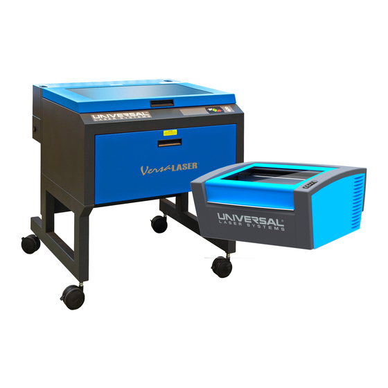
- Page 1 Installation & Set-up Guide VLS2.30, VLS3.50 www.ulsinc.com...
-
Page 3: Table Of Contents
Table of Contents Proper Operating Environment Environment…………………………………………………………………………………………………………………5 Electrical Power Source………………………………………………………………………………………………………6 Software Installation and Requirements Computer and Operating System Requirements……………………………………………………………………………9 Universal Control Panel (UCP) Installation CD-ROM………………………………………………………………………11 Assembling Your System System Assembly. ……………………………………………………………………………………………………………13 Checking Beam Alignment…………………………………………………………………………………………………17 Running Your First Job Step 1 - Loading and Positioning the Material.……………………………………………………………………………19 Step 2 - Creating the Graphic………………………………………………………………………………………………19 Step 3 - Printing to Your System……………………………………………………………………………………………20 Step 4 - Starting the Process………………………………………………………………………………………………21... - Page 4 Installation & Set-up Guide Thank you for choosing Universal Laser Systems®. We appreciate innovative customers like you who have made Universal Laser Systems an integral part of their business. Universal Laser Systems is committed to providing the highest level of customer satisfaction and support.
-
Page 5: Proper Operating Environment
Damage to the laser system due to inadequate or improper installation or operation is not covered under the Universal Laser Systems (ULS) Warranty. See the ULS Warranty for additional information. A ULS Warranty document is supplied with your laser system. Should you require a copy of the Warranty, please contact the ULS Customer Service Team at 480-609-0297 (USA), +43 1 402 22 50 (Austria), +81 (45) 224-2270 (Japan) or e-mail us at support@ulsinc.com. -
Page 6: Electrical Power Source
Installation & Set-up Guide Electrical Power Source (User Supplied) 1. For your system’s electrical requirements, please refer to the “INPUT POWER” label near the power inlet. CAUTION: Never remove the ground lead to the electrical cord and plug the laser system into a non-grounded outlet. - Page 7 The exhaust system must be capable of supplying a minimum of: a. VLS2.30 - 150 CFM (cubic feet per minute) of airflow while under a load of 6 inches of static pressure (254m3/hr at 1.5kPa) b. VLS3.50 - 250 CFM (cubic feet per minute) of airflow while under a load of 6 inches of static pressure (425m3/hr at 1.5kPa)
- Page 8 Installation & Set-up Guide VLS2.30 and VLS3.50 Exhaust blower mounted outside* (User Supplied) Weatherproof shield (User Supplied) Rigid ducting matching the diameter of the blower inlet (User Supplied) Shut-off or air-flow gate (User Supplied) Adapter to the hose reduces from 4” to 3” (User Supplied)
-
Page 9: Software Installation And Requirements
Software Installation and Requirements Step 2: Computer Requirements and Software Installation Your computer is a critical component in the operation of your laser system. In fact, you cannot operate the laser system if your computer is not connected, powered on, running Windows and running the Universal Control Panel (UCP) software. - Page 10 Installation & Set-up Guide Computer Power Management Power management settings on your computer can interfere with proper operation of the laser system by putting the PC in standby or sleep mode while the laser system is processing material. The settings can be controlled through the power options in the Windows control panel on your PC.
-
Page 11: Universal Control Panel (Ucp) Installation Cd-Rom
Software Installation and Requirements Software Installation At this point you need to install the Universal Control Panel (UCP) and printer driver. In order to install the software, you need to have administrative privileges on the computer before starting installation. Use the Software Installation CD-ROM included with your laser system. 1. - Page 12 Installation & Set-up Guide When the installation process is finished, the “Completing the ULS Software Setup Wizard” window will prompt you to reboot the PC to complete the installation. If you have any other applications running in windows make sure you save your work prior to rebooting. After the PC finishes rebooting, the software installation is complete and you are ready to connect your laser system to the PC.
-
Page 13: Assembling Your System
Assembling Your System Step 3: Assembling and Connecting Your Laser System Familiarize yourself with the instructions before getting started. The final step in installation is to assemble your laser system, install the laser cartridge, make final connections and perform a beam alignment check. Do not power up your laser system until the final step, “Checking Beam Alignment. -
Page 14: System Assembly
Installation & Set-up Guide Bend and connect the short exhaust hose (1) provided with the air filtration unit to the exhaust port on the back of the laser system and secure it with the provided hose clamps. Once the hose is attached, install the provided sheet metal cover over the exhaust hose. Attach a power cord to the air filtration unit’s power inlet (5), but do not plug into power outlet at this point. - Page 15 Assembling Your System 3. Using a flat blade screw driver, gently open the Thermal Sensor battery holder drawer on the back of the laser system as indicated and install the provided 9-volt battery into the battery holder. Note: A properly installed 9-volt battery is necessary to operate the laser system. The laser system will not function without a charged battery installed.
- Page 16 Installation & Set-up Guide Locate the “V” groove along the upper (3) and lower (2) part of the laser cartridge base plate and the alignment plate (1) at the end of the base plate. Pick up the laser cartridge by the ends and mount the cartridge onto the mounting blocks shown in step b by placing the upper “V”...
-
Page 17: Checking Beam Alignment
Assembling Your System 7. After connecting the USB cord, the “Found New Hardware Wizard” will open to install the drivers for the USB connection. If the wizard offers to connect to “Windows Update” to search for software, select “No, not at this time. ” Then select “Next” to continue. a. - Page 18 Installation & Set-up Guide With the top door open, a red target pointer will appear on the masking tape (3). The red target pointer should appear centered, within 1/8 inch (3 mm). If not, turn off the laser system, remove and re-install the laser cartridge and try again.
-
Page 19: Running Your First Job
0.0195 inch (0.49 mm) thick anodized aluminum test card supplied with your laser system. For additional test cards, please contact Universal Laser Systems’ Customer Service Team at 480-609-0297 (USA), +43 1 402 22 50 (Austria), +81 (45) 224-2270 (Japan) or e-mail us at support@ulsinc.com. -
Page 20: Step 3 - Printing To Your System
Installation & Set-up Guide Step 3 – Printing to the Laser System (Using the Materials Database Tab) 1. Verify that the Universal Control Panel (UCP) is running in the taskbar by looking for the square red icon. 2. When you are ready to print the job, select PRINT from the CorelDRAW FILE menu. -
Page 21: Step 4 - Starting The Process
Running Your First Job Step 4 – Starting the Process 1. Turn on the exhaust and laser system if not already on. Note: Laser system cooling fans are variable speed and may speed up and slow down during operation as needed to cool the lasers. 2. - Page 22 Notes...
- Page 23 ©2012 Universal Systems, Inc. All Rights Reserved. The Universal Laser Systems logo and name are registered trademarks of Universal Laser Systems, Inc. All other company and product names are trademarks or registered trademarks of their respective companies. Universal’s laser systems are protected under one or more of U.S. Patents: 5,661,746; 5,754,575; 5,867,517; 5,881,087; 5,894,493;...
- Page 24 www.ulsinc.com CPT CO058-123112 REV2012.10...
Need help?
Do you have a question about the VLS2.30 and is the answer not in the manual?
Questions and answers