Advertisement
Quick Links
Advertisement

Related Manuals for Universal Laser Systems ULTRA X6000


Summary of Contents for Universal Laser Systems ULTRA X6000
- Page 1 ULTRA X6000 Laser System User Guide www.ulsinc.com Version 2020.06.0102...
- Page 2 Universal Laser Systems, Inc.™ name and logo are registered trademarks. Digital Laser Material Processing (DLMP™) technology, Rapid Reconfiguration™ technology, 1-Touch Laser Photo™, MultiWave Hybrid™ technology and SuperSpeed™ are trademarks of Universal Laser Systems. All other company and product names mentioned herein are trademarks or registered trademarks of their respective companies.
-
Page 3: Table Of Contents
Table of Contents 1. ULTRA X6000 Platform Overview ................5 2. Safety ........................13 3. Meet the ULTRA X6000 Platform ................27 4. Laser System Manager (LSM) Overview ............... 33 5. The ULTRA X6000 Workflow ................77 6. Maintaining the Laser System ................81... - Page 4 This page left intentionally blank.
-
Page 5: Ultra X6000 Platform Overview
The ULTRA X6000 Platform has a materials processing envelope of 36 x 24 in. (914 x 610 mm), with support for materials with a thickness up to 12 in. (305 mm) and may be configured with up to three laser sources. - Page 6 Specifications, Features, and Options FEATURE DESCRIPTION 36 x 24 in. (914 x 610 mm) Processing Area Supports up to three laser sources of different wavelengths. Compatible Laser Sources: 10.6 µm | 10, 30, 50, 60, 75, and 150W power single sources •...
- Page 7 Equivalent to more than 300 in. /sec (equivalent to more than 7620 Maximum Effective Raster mm/sec) − Requires the SuperSpeed module. Material Processing Speed Maximum Functional Vector 75 in./sec (1905 mm/sec) Processing Speed Repeatability of ± .0025 in. (63.5 micron) using motorized focus assembly Precision Material- and high-resolution touch sensor.
- Page 8 E-STOP mechanisms is immediately shut off, while aborting all system operations. In the event an obstruction from any direction or axis interferes with the motion system, the ULTRA X6000 laser system immediately stops and Collision Detection disables its servo motors.
- Page 9 Note: *Denotes Optional Feature Disclaimers Universal Laser Systems® reserves the right to change these specifications at any time, and without notification. Material processing results are affected by ambient temperature, material temperature, processing environment temperature, humidity, laser processing settings, and material characteristics.
- Page 10 Laser System Manager Control Software FEATURE DESCRIPTION The Intelligent Materials Database generates laser processing parameters for a wide variety of material and laser system configurations. Intelligent Materials If the system configuration changes, the database automatically Database recalculates the parameter values. User controls to reposition or duplicate design files anywhere within the Design File Relocation and Duplication Controls...
- Page 11 ULTRA X6000 Platform Dimensional Drawings ULTRA X6000 Platform (Front View ). All dim ensions are indicated in inches and m illim eters.
- Page 12 ULTRA X6000 Platform (Side View ). All dim ensions are indicated in inches and m illim eters.
-
Page 13: Safety
Administration (FDA) or other similar governmental entities. General Safety Use of the ULTRA X6000 Platform in a manner other than described in this manual or failure to follow the operational instructions and safety guidelines listed in this manual can result in personal injury and may cause damage to the operator, the equipment, and the surrounding property. - Page 14 It is also designed for connection to IT power systems. To satisfy European Standard EN 610000-3-11 for Voltage Fluctuation and Flicker, the ULTRA X6000 laser system must be connected to an AC supply with a low impedance (Zmax=0.049 OHMs) or less. End users may consult with a power supply authority to ensure their AC supply line impedance meets the requirements of EN 61000-3-11:2000 Annex B for low impedance connections.
- Page 15 Laser Safety The ULTRA X6000 Platform is designed to support both sealed carbon dioxide (CO ) laser sources, which produce intense invisible infrared laser radiation at 10.6 µm and 9.3 µm wavelengths, and fiber laser sources that produce intense invisible infrared laser radiation at 1.06 µm wavelength. For optimal...
- Page 16 Laser Safety When Using Class 4 Pass-Through The ULTRA X6000 laser system is equipped with interlocked access panels on either side of the unit. An Optional Class 4 Pass-Through Module is available to enable the user to operate the laser system with the side access panels open by bypassing their safety interlocks.
- Page 17 Class 4 laser system. Certain safety measures are provided by the manufacturer and incorporated into the optional Class 4 Pass-Through module while other operational safety measures are the responsibility of the ULTRA X6000 laser system Owner. MANUFACTURER PROVIDED CLASS 4 SAFETY MEASURES Remote Interlock Connection –...
- Page 18 servicing a Class 4 laser system. The LSO will ensure that no juveniles operate the laser. • The LSO will regularly audit all safety measures including: regular retraining of authorized • personnel, serialization and regular inspection and replacement of all special eyewear and clothing, and monitoring of all safety measures surrounding the controlled area in which a Class 4 laser system is operated.
- Page 19 ULS CO Laser Source Safety Labels...
- Page 20 ULS Fiber Laser Source Safety Label...
- Page 21 ULTRA X6000 Platform Safety Labels (I som etric Side View )
- Page 22 ULTRA X6000 Platform Safety Labels (Rear View )
- Page 23 ULTRA X6000 Platform Safety Labels (Left View )
- Page 24 Class 4 Pass-Through Safety Labels...
- Page 25 EU Declaration of Conformity Product Identification: ULTRA X6000 Laser System Manufacturer: European Office: Universal Laser Systems, Inc. Universal Laser Systems GmbH 16008 N. 81 Lerchenfelder Guertel 43 Scottsdale, AZ 85260 A-1160 Vienna/Austria The manufacturer hereby declares that the equipment specified is in conformity with the...
- Page 26 Therefore, we urge consumers to recycle this product and its accessories. Universal Laser Systems is equipped to recycle any of its electronic products and accessories and will assist our customers with their recycling options.
-
Page 27: Meet The Ultra X6000 Platform
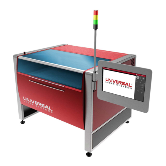
Meet the ULTRA X6000 Platform... - Page 28 THE ULTRA X6000 PLATFORM (FRONT VIEW) FEATURE DESCRIPTION Top Door Enables safe viewing of the laser process and materials loading. Front Door Provides access to easily load large materials and fixtures. Touch Screen Provides operational controls. Control Pane Instantly de-energizes the system when depressed.
- Page 29 Beam Delivery Positions the carriage in the laser processing field. System Carriage Contains the final focusing optic, autofocus sensor, and the camera. Holds the material in place during laser material processing, supports Multifunction the elevating pins, aluminum and carbon tiles and provides through- Material Support table vacuum hold-down.
- Page 30 THE ULTRA X6000 PLATFORM (REAR VIEW) FEATURE DESCRIPTION Provides 10.6 µm and/or 9.3 µm wavelengths of CO laser radiation Laser Sources for material processing. Provides 1.0 6µm wavelength of laser radiation for material Fiber Laser Source processing. Covers the top portion of the CO Laser Sources.
- Page 31 ULTRA X6000 PLATFORM CONNECTIONS (UNDER TOP REAR LASER COVER) FEATURE DESCRIPTION ¼ in. quick connect coupler that supplies compressed air during Air Assist Connection material processing. ¼ in. quick connect coupler that supplies compressed gas during Gas Assist Connection material processing.
- Page 32 This page left blank intentionally.
-
Page 33: Laser System Manager (Lsm) Overview
Laser System Manager Overview The LSM (Laser System Manager) is the software interface used to control the ULTRA X6000 Laser System, manage control files, setup processes, etc. The following Quick Reference Guide provides a brief overview of the functionality of the LSM. - Page 34 FEATURE DESCRIPTION Opens the System Operation Page to control the laser system setup Systems Operation control files, adjust settings, etc. This page is the default page for Page the LSM. Opens the Control File Page to manage the queue of control files Control File Page stored in the LSM and to import new files.
- Page 35 System Operation Page The primary location for laser system controls is the System Operation Page. The system may be positioned, set up, and run from this page. This default page is the most used in the LSM. The system controls screen as seen on the control panel. M otorized Z Axis version show n above. FEATURE DESCRIPTION Opens the Main Menu on the left-hand side of the LSM.
- Page 36 Opens the Camera View as the current menu on the right-hand Camera View side of the LSM. For further details, refer to the Camera View Section of this manual. Enters the Settings View as the current menu on the right-hand Settings View side of the LSM.
- Page 37 FOCUS VIEW CONTROLS These controls are primarily used to position and locate the motion system across each axis, and for positioning the material to be laser processed. Several of these controls are duplicated in other views. System controls for system s w ith a fixed Z-Axis (left) and a m otorized Z-Axis (right). FEATURE DESCRIPTION Initiates laser material processing, during which time, the button will...
- Page 38 Moves the system along the X and Y Axes simultaneously. Touch and drag the central button to manually adjust the system position. Tapping on any of the four arrows will generate incremental XY Axis Joystick movements in the associated direction (Up, Down, Left, and Right). The size of these movements is determined by the Tap Sensitivity Adjustment Button (H).
- Page 39 Z Axis Location Provides the exact location of the material support structure (Z Indicator Axis). Units are adjustable in the Systems Configuration Page. Performs the homing routine on the Z Axis. This will cause the material support structure (Z Axis) to move downwards and Home Z Axis Button reestablish the home position.
- Page 40 RELOCATION VIEW CONTROLS This set of controls manages the location of the design file within the Design Preview Area. Design files may be located manually, relatively, or in coordination with the systems X and Y Axes. FEATURE DESCRIPTION Acts as both indicators and buttons for the nine anchor points on the design file.
- Page 41 DUPLICATION VIEW CONTROLS These controls relate to duplication of a design file within the Design Preview Area. They provide a convenient method to create multiple impressions of a single design file within the LSM. FEATURE DESCRIPTION Provides fields to Indicate the number of Columns and Rows desired for duplication of the current design file.
- Page 42 Provides fields for adjustment of the design file duplication gap in both the X and Y directions. The gap is the space between the outermost Duplication Gap extents of the design file. Dialog Changing either the pitch or gap will override any previous pitch or gap settings.
- Page 43 CAMERA VIEW CONTROLS The camera onboard the ULTRA X6000, seen in this view, is used for camera registration and calibration. FEATURE DESCRIPTION Camera View Area Shows the current view of the camera onboard the carriage. Indicates the centerlines of the camera. This is primarily used for Camera Crosshair camera registration purposes.
- Page 44 The Process Settings Tab is the primary location used for setup, ordering, and configuration of the various processes that are possible on the ULTRA X6000 laser system. Individual processes are assigned a set of colors that correspond to graphical elements within the design file.
- Page 45 Rotary Axis Enables or disables the optional Rotary Axis Module. When enabled, a Module Required yellow line will be marked horizontally through the design preview area Switch and the Y Axis controls will be replaced with the associated R Axis controls. Lists all processes with their assigned colors.
- Page 46 Raster Settings Tab Contains settings common to all raster elements of a design file. FEATURE DESCRIPTION Determines the direction the raster motion will progress throughout the Processing control file. Down will start at the top of the control file and make its way Direction downward.
- Page 47 Indicates the type of margin to be used for the raster process. Tight will reduce the overall processing time by moving only the required amount in the X Margin direction for each raster stroke. Frame will make each raster stroke the same length over the entire process –...
- Page 48 Vector Settings Tab Contains settings common to all Vector Processes set up in the Processes Tab (Database and Custom). FEATURE DESCRIPTION Processing Order Determines the processing order of the vector graphical elements Settings Inner-Outer will produce. This value corresponds to the amount of acceleration the system will undergo during processing.
- Page 49 DATABASE VECTOR MARK SETTINGS Uses the Intelligent Materials Database to generate laser processing settings for a Vector Marking process. FEATURE DESCRIPTION Indicates the process type. The interface above shows the Database Process Type Vector Selector Mark settings. If changed, the available settings will change to reflect the new process type.
- Page 50 If the system has multiple laser sources available for the selected Laser Type material, this drop-down menu may be used to select the laser type to be used for the selected process. The Intelligent Materials Database determines the appropriate laser Power power based on the material type, thickness, and selected laser type.
- Page 51 DATABASE VECTOR CUT SETTINGS Uses the Intelligent Materials Database to generate laser processing settings for a Vector Cutting process. FEATURE DESCRIPTION Indicates the process type. The interface above shows the Database Vector Process Type Cut settings. If changed, available settings will change to reflect the new Selector process type.
- Page 52 The Intelligent Materials Database determines the appropriate laser power based on the material type, thickness, and selected laser type. Power Power Adjustment adjustment enables users to fine-tune this value to accommodate deviations in material thickness or chemical formulations. Laser Enable Enables or disables each laser individually if more than one laser source is Disable Toggle available for the selected laser type.
- Page 53 DATABASE RASTER SETTINGS Uses the Intelligent Materials Database to generate laser processing settings for a Raster Marking Process. FEATURE DESCRIPTION Indicates the process type. The interface above shows the Process Type Selector Database Vector Cut settings. If changed, the available settings will change to reflect the new process type.
- Page 54 If the system has multiple laser sources available for the selected Laser Type material, this drop-down menu may be used to select the laser type to be used for the selected process. The Intelligent Materials Database determines the appropriate laser power based on the material type, thickness, and selected Power Adjustment laser type.
- Page 55 CUSTOM VECTOR SETTINGS This screen contains the controls needed to configure a Custom Vector Process. This process could be used to cut a material that is not found in the Intelligent Materials Database. FEATURE DESCRIPTION Indicates the process type. The interface above shows Custom Vector Process Type settings.
- Page 56 Displays the power percentage to be used for each laser. A power setting Power Setting may be set for each installed laser source. Displays the percentage of process speed applied to all colors in the Speed Setting process. Enables selection of the type of Gas Assist to be applied. Options include Gas, Air, and None.
- Page 57 CUSTOM RASTER SETTINGS This screen contains the controls needed to configure a Custom Raster Process. This process could be used to mark or engrave materials that are not found in the Intelligent Materials Database. FEATURE DESCRIPTION Indicates the process type. The interface above shows the Custom Raster Process Type settings.
- Page 58 Displays the process speed setting percentage to be applied to all colors in Speed Setting the process. Enables selection for the type of Gas Assist to be applied. Options include: Gas, Air, and None. If using Coaxial Gas Assist or the optional Lateral Gas Assist, either the Gas or Air option must be selected.
- Page 59 REGISTRATION SETTINGS This screen contains the controls needed to configure a Camera Registration Process. FEATURE DESCRIPTION Indicates the process type. The interface above shows the Registration Process Type settings. If changed, the available settings will change to reflect the new Selector process type.
- Page 60 DRILL SETTINGS This screen contains the controls needed to configure a Laser Drilling Process. FEATURE DESCRIPTION Process Type Indicates the process type. The interface above shows the Drill settings. If Selector changed, the available settings will change to reflect the new process type. Provides a field to enter a description of the process.
- Page 61 Enables selection of the type of Gas Assist to be applied. Options include Gas, Air, and None. If using Coaxial Gas Assist or the optional Lateral Gas Assist, either the Gas or Air option must be selected. Gas Assist Type If Gas or Air is selected for any process, all processes must have one or the other selected.
- Page 62 Starts the New Control File Wizard that enables the user to import design Import Control File files into the system from either the local drive or a USB flash drive. For Button remote use, the local drive will be used to access the ULTRA X6000.
- Page 63 Recipes Page Recipes are collections of settings generated by the user. They provide a convenient method to store and apply settings for commonly used setups and materials. FEATURE DESCRIPTION Displays a unique identifier for each recipe that is automatically Recipe ID assigned when the recipe is created.
- Page 64 System Configuration Page This page provides access to system-wide configuration options. FEATURE DESCRIPTION Enables users to select the measurement units to be used Units Selection Radio throughout the LSM by selecting one of two radio buttons: inches Buttons and millimeters. Enforce Fire Forces the system to check for the presence of a fully pressurized Suppression Checkbox...
- Page 65 Home XY Before Instructs the system to perform a homing routine prior to laser Processing Checkbox processing. Informs the system that a traveling exhaust module is installed. This Traveling Exhaust control adjusts motion system performance to accommodate the Enabled Checkbox extra weight of the traveling exhaust.
- Page 66 Calibration Page The ULTRA X6000 laser system provides a series of Wizards and Dialogs to aid in system calibration. All system calibration is performed first at the factory, then again during system installation. It is atypical to require use of these options frequently.
- Page 67 Automation Page This page is used to configure the Automation Interface to communicate with other equipment. FEATURE DESCRIPTION Displays the port number corresponding to the hardware port of the Port Number device with which the LSM will communicate. Connections may be accessed under the top laser cover on the back of the laser system.
- Page 68 User Details Page A currently logged in user can access a summary, log out, or change their password in the User Details Page. FEATURE DESCRIPTION User Name Indicates the currently logged in user. Logout Button Logs the current user out of the system. Change Password Enables the current user to change the password associated with their Button...
- Page 69 User Login Page When the laser system is configured to require login on startup or to access the ULTRA X6000 laser system from a remote location, this screen will appear. A valid Username and Password will be required to operate the laser system.
- Page 70 User Management Page Select this page to manage the users who have access to the laser system, and to indicate various permissions and capabilities specific to each one. FEATURE DESCRIPTION Overrides the default behavior of allowing anonymous laser system Require Login on operation.
- Page 71 Network Management Pages Enables the configuration of the ULTRA X6000 laser system to access either a wired or wireless network. Connection to a network is optional but enables several features such as Remote Diagnostics and Remote Operation. FEATURE DESCRIPTION Network Name of Gives the system a name for easy identification on attached networks.
- Page 72 When enabled, the system will automatically update the date and time. Automatic Date & When disabled, time and dates can be manually entered and updated as Time Toggle Button needed. IPv6 Wireless The network address of the system on the Wireless Network. Address IPv6 Wired Address The network address of the system on the Wired Network.
- Page 73 Feedback Page Feedback entered into this page is placed into the system log for future or diagnostic purposes. FEATURE DESCRIPTION Feedback Message Provides a field for the user to enter a message to be left in the log file. Field Record Feedback Saves a message typed into the Feedback Message Field to the local log Button...
- Page 74 Help & Diagnostics Page This page provides information useful for addressing system problems should they arise. FEATURE DESCRIPTION Generates a diagnostics.zip file that may be used to troubleshoot system Create Diagnostics issues should they arise. May be stored locally or moved to a USB flash drive.
- Page 75 Remote Diagnostics Remote Diagnostics enables a user to initiate a remote session with ULS Support to aid in system troubleshooting. During a remote session, the system must maintain a robust connection to the internet. FEATURE DESCRIPTION Remote Access Enables a user to initiate a session that gives a ULS Service Technician remote access to the laser system for troubleshooting purposes.
- Page 76 Software Update Software updates are routinely released to continuously improve the Laser System Manager (LSM) and laser system operation as well as add new features and laser material processing parameters to the Intelligent Materials Database. TITLE DESCRIPTION Currently Installed Displays the current software version installed on the system. Software Version Displays a list of the currently available software versions.
-
Page 77: The Ultra X6000 Workflow
ULTRA X6000 Laser M aterial Processing W orkflow Design File Creation ULTRA X6000 LASER SYSTEM MANAGER The software that runs the ULTRA X6000 Laser System is the Laser System Manager (LSM). It handles all aspects of importing, planning, arranging, organizing, and running design files to completion. - Page 78 To print a design file, a printer driver must be installed on the computer on which the design file is generated. Once a printer driver is loaded on a PC, the ULTRA X6000 Laser System acts as a network printer and can receive design files by simply using the design software’s print dialog. Once printed, the design file will be sent to the LSM and a control file is generated from the design file.
- Page 79 Control File Creation CONTROL FILES To begin modifying materials with an ULTRA X6000 laser system, a control file must first be created in the LSM. A control file contains the collection of raster image and vector path data in addition to the laser material processing parameters needed for a particular laser material processing application.
- Page 80 FOCUSING The laser system must be properly focused to the material for optimal results. The ULTRA X6000 laser system automatically focuses the system using a high accuracy touch probe that is configurable on a per-process basis.
-
Page 81: Maintaining The Laser System
Maintaining the Laser System It is essential to keep your laser system as clean as possible to ensure safe and trouble-free operation and to achieve the best results when laser processing. Accumulation of dirt and debris on the motion system components and failure to routinely perform maintenance on your laser system can impact performance or cause damage to the laser system. - Page 82 Clean the Z-Axis lead screws with white lithium grease as necessary Remove and clean the inside of the exhaust plenum Regularly inspect and clean your exhaust ducting to the laser system (consult with HVAC professional) Every 12 months: Remove upper left external side cover and upper X arm cover to clean and re-grease linear bearings...
Need help?
Do you have a question about the ULTRA X6000 and is the answer not in the manual?
Questions and answers