Table of Contents
Advertisement
Quick Links
Advertisement
Table of Contents

Related Manuals for Universal Laser Systems Laser Platform M-300


Summary of Contents for Universal Laser Systems Laser Platform M-300
- Page 1 M-300 Laser Platform Installation and Operations Manual Ihr ULS Vertragshändler : MarkIDent GmbH Winterspürerstr. 19 78333 Stockach www.markident.de Universal Laser Systems, Inc. 16008 North 81st Street Scottsdale, AZ 85260 Phone: 480-483-1214 Fax: 480-483-5620 May 2000...
- Page 2 This publication and its contents are proprietary to Universal Laser Systems, Inc. (ULS), and are intended solely for the contractual use of ULS, Inc. customers. While reasonable efforts have been made to assure the accuracy of this manual, ULS shall not be liable for errors contained herein o r for incidental or consequential damage in connection with the furnishing, performance, or use of this material.
-
Page 3: How To Get Help
We would like to thank you for purchasing the M-300 Laser Platform. Years of testing and refinements have made this unit the ultimate laser engraving and cutting system. With it’s small footprint design and industry standard 24” x 12” work area, the M-300 Laser Platform is now equipped with our unique “Rapid Reconfiguration Capability ”. -
Page 4: Table Of Contents
Table of Contents SECTION 1 - Safety Description of Appropriate Use ... 1-1 General Safety ... 1-1 Laser Safety... 1-2 Safety Labels ... 1-3 FCC Compliance... 1-6 EU Compliance (CE) ... 1-7 SECTION 2 - Installation Operating Environment ... 2-1 Electrical Requirements ... - Page 5 Setting the Drivers Properties ... 4-3 Downloading the File ... 4-3 Starting the Engraving Process... 4-4 Material Removing and Reloading ... 4-5 SECTION 5 - Options & Accessories 3D Effects ... 5-1 Rotary Fixture... 5-5 Cutting Table ... 5-6 Air Assist System... 5-7 Air Assist Compressor...
- Page 6 SECTION 7 - Maintenance Suggested Cleaning and Maintenance Supplies ... 7-1 System Cleaning ... 7-3 Optics Cleaning ... 7-3 AUTOFOCUS Sensor and Reflector ... 7-6 Adjustments and Lubrication... 7-7 Electronic Upgrading... 7-7 Fuse Replacement ... 7-7 Battery Replacement ... 7-7 Cooling Fan Filter(s) ...
-
Page 7: Section 1 - Safety
SECTION 1 Safety This section describes hazards that may occur if the laser system is installed or used improperly. Failure to follow these guidelines can result in injury to yourself, others, or may cause severe damage to the equipment. Use, misuse, or abuse of the equipment in a manner other than what is described in this manual may increase this risk. -
Page 8: Laser Safety
1-2 Safety Care should be taken when moving or lifting this device. Obtain assistance from 1 or 2 additional people when lifting or carrying. Severe bodily injury may occur if improper lifting techniques are applied. Be careful not to drop the unit. Not only can it cause bodily harm, but it can also severely damage the equipment and render it inoperable. -
Page 9: Safety Labels
Do not modify or disable any safety feature of this system. Do not operate any system that has had its safety features modified, disabled, or removed. Improper use of controls and adjustments, or performance of procedures other than those specified in this manual, may invalidate the safety of this system. - Page 10 Safety Rear View (cover closed) CAUTION LASER RADIATION DO NOT STARE INTO BEAM OR VIEW DIRECTLY WITH OPTICAL INSTRUMENTS CLASS 3A LASER PRODUCT LASER DIODE WAVELENGTH: 630-680 nm MAX. OUTPUT: 5 mW CDRH – United States CE - European...
- Page 11 Safety Upper left corner of the engraving area next to the Beam Window SERIAL #: 02500A DATE : MAY 2000 D A N G E R CAUTION LASER RADIATION LASER RADIATION - AVOID EYE AVOID EYE OR SKIN EXPOSURE OR SKIN EXPOSURE TO DIRECT OR SCATTERED RADIATION TO DIRECT OR SCATTERED RADIATION CLASS 4 LASER...
-
Page 12: Fcc Compliance
Safety FCC Compliance This ULS laser system has been tested and found to comply with Federal Communication Commission (FCC) directives regarding Electromagnetic Compatibility (EMC). In accordance with these directives ULS is required to provide the following information to its customers. FCC Compliance Statement and Warnings This device Complied with FCC Rules Part 15. -
Page 13: Eu Compliance (Ce)
EU Compliance (CE) L A S E R S Y S T E M S Product Identification: Manufacturer: Universal Laser Systems, Inc. hereby declares that the equipment specified below is in conformity with the following directives: 89/336/EEC 73/23/EEC 89/392/EEC based on the standards listed. Standards Used: Safety: EN 60950: 1995... -
Page 14: Section 2 - Installation
SECTION 2 Installation Proper operating conditions are vital to a safe and productive environment. describes the ideal environment and setup of the laser system. Operating Environment Follow these guidelines to ensure a proper operating environment for the laser system. Operating the laser system outside of these guidelines can seriously damage the laser system and damages from this type of abuse WILL NOT be covered under warranty. -
Page 15: Electrical Requirements
Installation If planning to connect the laser engraving system to a computer through the parallel port, choose a location where the computer will be placed within 6 feet of the machine since this is the maximum recommended parallel cable length. Included with your system is a high quality, IEEE1284 compliant, 6 -foot parallel printer cable. -
Page 16: Exhaust Requirements
If electrical power fluctuations, brown outs, or constant power outages are a problem in your area, an electrical line stabilizer, UPS (Uninterruptible Power Supply), or backup generator might be required. If installing any of these devices, make sure that they meet the electrical requirements of the laser system. - Page 17 Installation DO NOT install forward incline, backward incline, in-line, or ventilator fans because these types of air handlers are inadequate and inappropriate for this type of installation. If your contractor has any questions concerning blower specifications or exhaust system requirements, please contact our Service Department directly before installation.
-
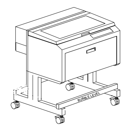
Page 18: Cart Assembly
Installation Cart Assembly Since packaging of this unit may vary from time to time, make sure that you locate the following items from within the crate or inside of the front door of the system: (A) Back Panel (B) Legs (both are identical) (C) 10-32 x 3/8 socket head screws with lock washers and flat washers (2) (D) Guide pins (factory installed) (E) Nuts (4) - Page 19 Installation 9. Note the lifting points as shown. With the assistance of one or two other people, carefully lift the laser system and place it onto the cart assembly being careful not to drop it or pinch your fingers. 10. Thread the remaining two screws and lockwashers (C) through the tabs on the back panel (A) and into the backside of the laser system.
-
Page 20: Laser Cartridge Installation
Installation Laser Cartridge Installation Before connecting and powering on your system, you must install the Laser Cartridge. Make sure that your power cord IS NOT plugged in at this time. With your fingers, press on the backside of the two hinges to release the latch. Gently fold back the rear cover. - Page 21 Installation Pick up the Laser Cartridge by the sides. Tilt the Laser Cartridge downward on a 30-degree angle. Mount the cartridge onto the Mounting Blocks by placing the upper “V” groove of the cartridge on top of the Mounting Blocks. Slide the cartridge to the right until the Alignment Plate of the Laser Cartridge makes contact with the inside of the large plate of the Alignment Fork and is centered in the gap in the Alignment Fork between the small and large plates of the Alignment Fork.
-
Page 22: Laser Cooling Requirements
Laser Cooling Requirements This type of laser system uses fans to keep the laser cartridge and electronics cooled during operation. Maintain the room temperature at the recommended ambient temperature range outlined previously in the Operating Environment section. Do not confine the back of the machine by surrounding it with furniture, shelving, backing it into a corner, etc. -
Page 23: Font Requirements
2-10 Installation Bitmap / Scanning Software Adobe Photoshop Adobe Streamline - for raster to vector conversion CAD Software AutoCAD for Windows AutoCAD LT for Windows Autosketch for Windows DesignCAD for Windows CAD users do not necessarily need Windows or Windows compatible programs. The laser system is compatible with any program that can output standard HPGL commands whether it is Windows based or not. -
Page 24: Making The Connections
Making the Connections Please use the parallel cable supplied with the system. It is a 6-foot, high quality, shielded, IEEE1284 compliant cable. If you use a printer cable other than the one provided, it will violate the laser systems FCC and CE rating and may also cause harmful interference when downloading files to the laser system. -
Page 25: Problem Prevention
2-12 Installation Problem Prevention The following are things that you MUST NEVER do: 1) Never connect or disconnect the printer cable while either the computer or the laser system is powered ON. the wall outlet when connecting or disconnecting the printer cable. 2) Never connect the laser system through a manual switch type A/B switch box. -
Page 26: Section 3 - System Operation
SECTION 3 System Operation In this section you will learn how the laser system actually works and will familiarize you with laser system terminology. We will then start working with the control panel and learn how to get around in the menu system. Since there are many features in this laser system, the menu system may seem complicated at first, but once you start using it, you will find out that it is a very simple system to operate. - Page 27 System Operation Laser Cartridge The laser cartridge is a very sophisticated device. It is composed of a plasma tube filled with a special mixture of CO2 and other gases, and RF (radio frequency) electronics. The function of the entire assembly is to turn electrical energy into concentrated light energy. The word LASER is an acronym for Light Amplified Stimulated Emission of Radiation.
-
Page 28: The Control Panel
System Operation “Wattage” signifies the amount of heat energy that the laser light is producing over a period of time. Laser energy is measured with a laser power meter. Do not confuse the electrical wattage rating of a light bulb or a hair dryer with the wattage rating of the laser system. They are two different types of measurements. - Page 29 System Operation The Liquid Crystal Display (LCD) The LCD is a four line display that displays the menus that control the laser system. It is a backlit type of display that enhances visibility even under low light environments. When the laser system is powered on, the laser system will perform a series of routines. “INITIALIZING”...
- Page 30 CONDITION The laser system is powered up, the top door is closed and the system is ready to receive a file The laser system has finished processing a file and has returned to the home position The laser system has been paused while running a file The top or front door is open The laser system is firing the beam in the Alignment Mode FLASHING...
- Page 31 System Operation The “NEXT FILE” button displays the next file in the systems memory and makes it the current file and will stop at the last file in memory. The “PREV FILE” button displays the previous file in the systems memory and makes it the current file and will stop at the first file in memory. These buttons are inoperative if a file is currently running.
-
Page 32: The Menu System
System Operation The Menu System The LCD displays the menus of the laser system. Since this laser system has many features, we have included a “Menu System Flow Chart” on the next three pages. It diagrams and displays the menu items in the entire system and the button selections needed to access them. A description of each menu item follows the flow chart. - Page 33 System Operation...
-
Page 34: Menu Descriptions
System Operation MODEL NAME VERSION XX-XX-XX-XX Menu Descriptions The remainder of this section will describe each one of the menus and their significance. READY Menu When the system is first powered on “INITIALIZING” will appear for approximately 30 seconds until the laser system finishes performing its routine. When the system has finished initializing, “READY”... - Page 35 3-10 System Operation FILE DISPLAY Menu Appears automatically after the first file is downloaded completely into the laser systems memory. This is the menu that you will remain in most of the time when operating the laser system. It has been designed to show all pertinent operating information at a glance so that constantly jumping from menu to menu is not needed.
- Page 36 System Operation 3-11 There are two ways that a d ownloaded file will have a missing EOF. The first is if printing through the printer driver and printing is canceled, interrupted, or file size exceeds the remaining free memory space. If this occurs, chances are that the EOF never made it to the memory buffer and the memory buffer will show that it is empty or that the file does not exist.
- Page 37 3-12 System Operation The Printer Driver compresses the file while it downloads to the laser system and the laser system decompresses the file while it runs. The amount of compression can be as little as 4 to 1 or as great as 48 to 1. This means that with 4 MB of RAM in the laser system, the buffer could hold the equivalent of 192MB worth of files provided they can be compressed 48 to 1.
- Page 38 System Operation 3-13 DOS POWER SETTINGS Menu The laser system allows eight different power settings to be saved, in non-volatile (permanent) memory, and used when processing a DOS based file. Since DOS based printer/plotter drivers do not have the ability to set the “POWER”, “SPEED”, and “PPI” settings, the settings must be set manually on the laser system.
- Page 39 3-14 System Operation OPTIONS Menu Selecting this menu will allow the access to turn on certain options that the laser system might have. ONE FILE MEMORY Menu Pressing “SELECT” key while cursor is on this line will toggle the setting on and off. When off, it enables the multiple file memory buffer system (default).
- Page 40 System Operation 3-15 AIR ASSIST Menu This class of laser system does have Air Assist as an option, but it is not computer controlled. Since we use the same menu system on other models, this menu selection for your model does absolutely nothing.
- Page 41 3-16 System Operation To restore the focus position back to the original factory setting, go back into this menu and press the up and down arrow keys simultaneously. You will see the motion system move to the 1 inch horizontal and the 1 inch vertical position (factory default).
- Page 42 System Operation 3-17 If you would like to get the Rotary axis back to the original factory default setting, go back into the “SET ROTARY AXIS” menu. While in this menu, press the up arrow and down arrow keys simultaneously. The arm move will move back to its original factory default setting. Select “YES SAVE Y-AXIS”, and then press the “ESCAPE”...
- Page 43 3-18 System Operation In order to use the “SERIAL” port, the communication settings MUST match those of the computer. Refer to the computer’s hardware and software manuals for details on setting up the computer’s serial port. If using the “SERIAL” port, select the fastest possible “BAUD” rate for communication since this effects how quickly the computer can send files to the laser system.
- Page 44 System Operation 3-19 DIAGNOSTICS Menu This menu leads to other menus that enable you to help diagnose problems, if they occur, with the laser system. It also will help our technicians solve problems that you may be experiencing. ALIGNMENT MODE Menu This menu allows access to firing the laser beam manually to determine if the laser systems optical alignment is correct.
- Page 45 3-20 System Operation MODEL NAME VERSION XX-XX-XX-XX ABOUT Menu Use the up and down arrow buttons to position the cursor on this menu item. Press the “SELECT” button and our copyright notice along with the current versions of firmware will be displayed.
-
Page 46: Focusing The Laser Beam
System Operation 3-21 Setting a new origin other than the default (0,0) position will shrink your field size. If you already have files already loaded into memory that utilize the entire engraving area, and you set a new origin, part of that graphic might fall out of the effective printing area. If you run this file, unexpected results can occur that might destroy your material in the engraving area. - Page 47 3-22 System Operation The cursor in the display will be flashing on top of the tenths digit. You can now move the table up or down by pressing either the up or down arrow button. If you push the button once and let go quickly, the table will move in .1 inch increments.
- Page 48 System Operation 3-23 If you find that you need to place your materials in a position other than the upper left hand corner, you can change the default focus position to anywhere in the field that you like. Please refer to that menu item selection earlier in this section. The Material Thickness (Z POSITION) Method The second method is to enter in the thickness of the material into the “Z POSITION”...
- Page 49 3-24 System Operation The AUTOFOCUS Method In order to use this method, you must first turn it ON. We described how to turn it ON earlier in this section. After you turn it ON, please follow the step by step instructions below. To Use AUTOFOCUS: The AUTOFOCUS sensor sends out an invisible beam across the table between the 1 inch and the 3 inch mark in the Y axis ruler for the M-300 Platform and the 2 and 4 inch mark for...
- Page 50 To Adjust AUTOFOCUS: From time to time, you may need to re-adjust your AUTOFOCUS. The only time that you should need to re-adjust the AUTOFOCUS is when you have received a new or different length Focus Lens, have recently Flash upgraded the operating system of the laser, or had a dirty sensor or reflector and are adjusting it after you have cleaned those parts.
-
Page 51: Section 4 - Running The System Step By Step
SECTION 4 Running the System Step by Step In this section we will cover how to completely use the laser system to create a product from start to finish. From powering on everything to removing the finished product from the system, we will cover the entire process step by step. -
Page 52: Focusing
Running the System Step by Step Focusing Before attempting to adjust the focal height, visually check to make sure that the table is down low enough to prevent the focus carriage from hitting into the piece of wood. With the top door still open, press the “Z” button on the control panel of the laser system. You will see the focus carriage move to the (1,1) position directly over the piece of wood. -
Page 53: Creating The Graphic
Running the System Step by Step It does not matter whether you bring the table up to go out of focus, or down, the effect is the same. You should experiment on some scrap material at another time and note the difference. In this example, we will engrave in precise focus. -
Page 54: Starting The Engraving Process
Running the System Step by Step Find the “PRINT” command within your graphics program and click on it. Depending on which graphics program you are using, the menu command “PRINT” may be in various locations within your program. Usually after clicking on “PRINT”, you will then need to click on “OK”. A status screen may now appear showing a percentage of completion. -
Page 55: Material Removing And Reloading
Running the System Step by Step We will also remind you again to please comply with the warning label below. Material Removing and Reloading Once the laser system has completed processing you material, the laser beam will turn off, the motion system will move to its home position in the upper right hand corner, the system will beep twice, and the green light on the control panel will glow continuously. -
Page 56: Options And Accessories
SECTION 5 Options & Accessories There are several options and accessories available for this laser system. The new 3D Effects option is now available as a standard feature. The Rotary Fixture, Cutting Table, Air Assist System, Air Assist Compressor, various Focus Lens Kits, and the Dual Head option are available at additional cost. - Page 57 Options & Accessories PREVIOUSLY COMPLETED STAMPS COMPUTER GRAPHICS SCREEN COMPUTER GRAPHICS SCREEN Place the stamp (on screen) where you want it to engrave in laser system. Avoid the spots where you have already engraved and cut out other stamps. PREVIOUSLY COMPLETED STAMPS LASER ENGRAVING TABLE...
- Page 58 Options & Accessories 5-3 Settings for a 30 Watt System There is a considerable difference between rubber blends, thickness, and hardness between different manufacturers. Use these setting as a starting point for a 30 Watt system. You might need to experiment with different settings to obtain the desired results. As you can see, we set the page size in the driver equal to the graphics programs page size.
- Page 59 Options & Accessories Full Sheet Method The second method is to create a full sheet of rubber stamps and engrave them all at the same time. First create a stamp as a positive image as shown below. Create more stamps to fill the entire page. They can be the same stamp or different ones. If desired, output the page to a paper printer for proofreading.
-
Page 60: Rotary Fixture
Options & Accessories 5-5 In the laser systems printer driver, use the same settings as the previous example but with only minor modifications. In the “3D Effects” tab, select all three “Special” options; “Add Shoulder”, “Print as Negative Image” and “Print as Mirror Image” as the diagram below illustrates. Print to the laser system. -
Page 61: Cutting Table
Options & Accessories The Rotary Fixture is placed on the engraving table as the following diagram illustrates. Please refer to the instructions supplied with the Rotary Fixture on how to properly install and use this option. Cutting Table The purpose of the Cutting Table is to support the material that you are cutting off of the engraving table’s surface to minimize surface contact area. -
Page 62: Air Assist System
Options & Accessories 5-7 Air Assist System The Air Assist System consists of a nozzle that attaches to the focus carriage, Optics protection adapters, tubing, mounting brackets, needle valve, and pressure gauge. The purpose of this system is to force air or other types of gases directly onto the surface of your material to reduce the burning effects of the laser beam and helps disperse the smoke and gases created when cutting or engraving materials. -
Page 63: Focus Lens Kits
Options & Accessories Focus Lens Kits There are three optional Focus Lens Kits available other than the standard 2.0”, they are the 1.5”, 2.5”, and the 4.0” kits. Included in these kits are the focus lens, #3 mirror, front plate, thumbscrews, and a focus tool. - Page 64 Refer to the following chart for spot sizes and focal ranges of the lenses available. FOCAL LENGTH 1.5 “ 2.0 “ 2.5 “ 4.0 “ If you would like to order any of the accessories described in this section, please speak with your salesperson or call us directly to place an order or to get current pricing.
-
Page 65: Section 6 - Sample Materials
SECTION 6 Sample Materials This section provides sample driver settings and helpful hints to get started engraving and/or cutting the materials listed. Safety NEVER LEAVE THE LASER SYSTEM RUNNING UNATTENDED FOR ANY REASON. Exposure to the laser beam can cause ignition of combustible materials. All laser cutting and engraving should be constantly supervised. -
Page 66: Materials
Sample Materials Laser engraving or cutting materials other than those described in this manual can be a safety hazard and can damage the laser system. The laser system operator is liable for any damages caused, in whole or in part, for any economic loss, physical injury, lost revenue, lost profits, lost savings or other indirect, incidental, special or consequential damages incurred. -
Page 67: Acrylic - Cast And Extruded
Sample Materials NOTE When engraving very small objects, top speed cannot be achieved because acceleration and deceleration of the motion system requires time and distance. The laser system will automatically adjust itself to a maximum engraving speed that it can achieve due to the size and position of the graphic. - Page 68 Sample Materials LIGHT RASTER ENGRAVING LASER WATTAGE DEEP RASTER ENGRAVING LASER WATTAGE VECTOR ENGRAVING LASER WATTAGE VECTOR CUTTING LASER WATTAGE ACRYLIC - CAST AND EXTRUDED POWER SPEED POWER SPEED POWER SPEED POWER SPEED PASS DEPTH .001” .001” .001” .001” .001” .001”...
- Page 69 Sample Materials COMMENTS There are two types of acrylic available, cast and extruded. Cast turns white or frosted and extruded remains clear when engraved. Use extruded acrylic for paint filled engraving and cast for regular engraving. Cast engraves better without masking. Lightly engrave the surface to frost it with a low power setting such as the first setting listed above.
-
Page 70: Acrylic - Mirrored
Sample Materials LIGHT RASTER ENGRAVING LASER WATTAGE DEEP RASTER ENGRAVING LASER WATTAGE VECTOR ENGRAVING LASER WATTAGE VECTOR CUTTING LASER WATTAGE ACRYLIC - MIRRORED POWER SPEED POWER SPEED POWER SPEED 1000 1000 1000 1000 1000 1000 1000 1000 POWER SPEED 1000 1000 1000 1000... - Page 71 Sample Materials COMMENTS Engraving mirrored acrylic is similar to engraving regular acrylic. The idea is to engrave through the mirrored backing enough to begin to penetrate into the acrylic. Engraving deeply will cause a crusty residue to form just like with non-mirrored acrylic. A double image will appear if engraving on the front side of the mirror.
-
Page 72: Anodized Aluminum
Sample Materials RASTER ENGRAVING LASER WATTAGE VECTOR ENGRAVING LASER WATTAGE There is a process called Laser Color Marking which enables the color filling of anodized aluminum. First, coat or spray the aluminum with a clear acrylic finish. After the finish has thoroughly dried, laser engrave the graphic onto the aluminum. -
Page 73: Brass - Painted
RASTER ENGRAVING LASER WATTAGE VECTOR ENGRAVING LASER WATTAGE The manufacturing processes for coated brass varies from one vendor to another. Some manufacturers do not polish the brass before coating it. Since CO not engrave into metals when the coating is removed, the tarnished brass underneath will have a dull appearance that will need to be polished with a brass polishing compound. -
Page 74: Corian / Avonite / Fountainhead
6-10 Sample Materials CORIAN / AVONITE / FOUNTAINHEAD RASTER ENGRAVING LASER WATTAGE DEEP RASTER ENGRAVING LASER WATTAGE VECTOR ENGRAVING LASER WATTAGE If paint filling, mask the material first, then engrave through the masking. In this way, when ready to paint fill, the material is already masked. Spray painting seems to be the easiest. Use the paint sparingly. -
Page 75: Cork
RASTER ENGRAVING LASER WATTAGE VECTOR ENGRAVING LASER WATTAGE VECTOR CUTTING LASER WATTAGE Cork is not very popular for engraving but it does engrave and cut nicely. Cork is mainly used for making gaskets by vector cutting the gasket patterns. LASER CUTTING THIS MATERIAL CAN CAUSE FLAMING AND SPARKING. -
Page 76: Delrin (Seal Press)
6-12 Sample Materials RASTER ENGRAVING LASER WATTAGE VECTOR CUTTING LASER WATTAGE MALE seal presses into the female side. Once the seal is made and fastened to the press, make several impressions onto 400 grit sandpaper to smoothen out the edges of the plastic. Make sure you turn the sandpaper over to get both sides of the seal. -
Page 77: Glass / Crystal
RASTER ENGRAVING LASER WATTAGE COMMENTS: Engrave at 333 DPI VECTOR ENGRAVING LASER WATTAGE Glass engraving is different from other types of engraving. A CO glass nor can it cut glass. Instead, laser interaction with glass causes the surface of the glass to appear frosted. -
Page 78: Leather
6-14 Sample Materials RASTER ENGRAVING LASER WATTAGE VECTOR ENGRAVING LASER WATTAGE VECTOR CUTTING LASER WATTAGE Leather is a very simple material to engrave and most types of leather engrave very well with the laser system. Simulated leather engraves well also, but the results are not as nice as with the real thing. -
Page 79: Marble
RASTER ENGRAVING LASER WATTAGE VECTOR ENGRAVING LASER WATTAGE Most marble and polished stones will turn white when engraved. Masking is not necessary and light engraving works out better than heavy and deep engraving. Engraving deeply will cause a highly detailed image to appear washed out. The objective is to engrave deep enough to turn the marble white and provide a good contrast. -
Page 80: Mat Board
6-16 Sample Materials RASTER ENGRAVING LASER WATTAGE VECTOR ENGRAVING LASER WATTAGE VECTOR CUTTING LASER WATTAGE Mat board (thick cardboard) is a n excellent material to use for architectural modeling and for picture framing. It cuts and engraves very neatly and cleanly. It comes in a variety of shades and colors. -
Page 81: Melamine
MELAMINE - STANDARD ENGRAVING LIGHT RASTER ENGRAVING LASER WATTAGE DEEP RASTER ENGRAVING LASER WATTAGE VECTOR ENGRAVING LASER WATTAGE Engraving melamine is very similar to engraving regular wood with the added benefit of a consistent surface finish and uniform base material composition. Unlike regular wood that has grain patterns and density variations, melamine, when laser engraved, produces a flat and even engraved area. -
Page 82: Melamine - Photo/Clipart Engraving
6-18 Sample Materials MELAMINE - PHOTO/CLIPART ENGRAVING RASTER ENGRAVING LASER WATTAGE COMMENTS: Engrave unmasked. Use a resolution of 500 DPI. RASTER ENGRAVING LASER WATTAGE COMMENTS: Engrave unmasked. Use a resolution of 250 DPI. Engraving photographs can be challenging at first but becomes easier once there is an understanding of what to look for and how to achieve the desired results. -
Page 83: Plastic - Engravers Microsurfaced
PLASTIC - ENGRAVERS MICROSURFACED RASTER ENGRAVING LASER WATTAGE VECTOR CUTTING LASER WATTAGE Laser engraveable plastic comes in many different colors, thickness, coatings, and surface textures. Most engravers plastic will engrave and cut well with the laser system as long as it is microsurfaced and formulated for laser engraving. -
Page 84: Rubber Stamps
6-20 Sample Materials RASTER ENGRAVING LASER WATTAGE 15 (Not recommended) 20 (Not recommended) PERFORATED VECTOR CUTTING LASER WATTAGE 15 (Not recommended) 20 (Not recommended) To create a rubber stamp, use the “3D Effects” tab in the driver (Section 3). In the above example, only one pass is necessary to achieve a deeply engraved rubber stamp. -
Page 85: Sign Vinyl
RASTER ENGRAVING LASER WATTAGE VECTOR CUTTING (KISS CUT) LASER WATTAGE Sign vinyl comes in a wide variety of colors, patterns, thickness, finishes, and reflectivity. There are a few methods for using sign vinyl with the laser system. One method is to vector cut (unmasked) through the vinyl but not through the backing. - Page 86 6-22 Sample Materials RASTER ENGRAVING LASER WATTAGE VECTOR ENGRAVING LASER WATTAGE VECTOR CUTTING LASER WATTAGE When engraving wood with a laser, a brown, maple syrup like residue will deposit on the surface of the wood. This is normal and impossible to eliminate by POWER, SPEED, or PPI changes. More residue will be present when engraving deeper and/or slower.
- Page 87 be easier to flood the masking, after engraving, with water. This will loosen the tape and it can be easily removed by rubbing it off by hand. In the vector cutting example, the wood was elevated from the table to let smoke and heat escape from underneath. If elevating the wood, mask and/or dampen the bottom side of the wood very lightly and the water acts as a heat sink to prevent the underside from flaming and charring.
-
Page 88: Section 7 - Maintenance
SECTION 7 Maintenance Keeping the laser system clean will ensure the highest quality engraving. The frequency of cleaning will depend entirely on the type of material being engraved, the performance of your exhaust blower, the operating environment, and the amount of laser system usage over a given period of time. - Page 89 Maintenance...
-
Page 90: System Cleaning
System Cleaning Turn off and unplug the laser system. Open the Top Door and thoroughly remove all loose dirt and debris from inside the machine with a vacuum cleaner. Clean the Engraving Table surface with either a soap solution, alcohol, or acetone, and paper towels. - Page 91 Maintenance #2 Mirror To gain access to the #2 Mirror, the mirror cover must be removed. Remove the thumbscrew, slide the cover to the right slightly and lift straight up. Inspect the #2 Mirror and clean it only if there is debris present. There are two ways to clean the mirror, with a moistened cotton swab or a moistened lens tissue.
- Page 92 Maintenance 7-5 #3 Mirror and Focus Lens You must remove the front cover to the Focus Carriage to gain access to the #3 Mirror and the Focus Lens. To do this, hold the front cover with one hand and with the other hand, remove the three(3) thumbscrews that attach the front cover to the Focus Carriage, and pull the front cover straight out.
-
Page 93: Autofocus Sensor And Reflector
Maintenance Beam Window The Beam Window is where the laser beam enters into the engraving area. It is located in the upper left hand corner of the engraving area against the back wall and is yellow in color. It is not necessary to remove the Beam Window for cleaning since it can only get dirty on the front side. -
Page 94: Adjustments And Lubrication
Adjustments and Lubrication There are no periodic adjustments required. The bearings in the motion system will self adjust to take up any clearances as they begin to wear. The belts are fiber reinforced and will not stretch under normal use so that periodic tension adjustment is not necessary. Optical alignment is not necessary because the laser and the #2 Mirror are fixed. -
Page 95: Cooling Fan Filters
Maintenance Cooling Fan Filters This air-cooled laser system will require periodic cleaning of the cooling fan filters. Since ambient air is used to cool the laser tube, the air must be filtered before it enters the inside of the laser system otherwise dirt and dust can build up inside of the laser system and damage it. -
Page 96: Section 8 - Troubleshooting
SECTION 8 Troubleshooting Engraving Quality Problem “Fuzzy” looking raster engraving or small text appears like a “double image” Fine detail is missing such as the serif’s of characters or thin lines of script fonts when raster engraving Vertical or diagonal background pattern present when raster engraving large areas and/or large amounts of material... - Page 97 Engraving disappears, becomes “lighter”, or appears “choppy” when raster engraving within ½ inch of Y-axis ruler Laser tube is faulty Normal condition. The laser system needs to accelerate and decelerate within this area Ihr ULS Vertragshändler : MarkIDent GmbH Winterspürerstr. 19 78333 Stockach www.markident.de Replace laser tube...
- Page 98 Troubleshooting Raster engraving appears sharp on both ends of the engraving but fuzzy in the middle Engraving does not appear as deep as it normally does Engraving is sharp, clear and at a good depth on one side of the table and fuzzy and shallow on the opposite side of the table Dirty laser system...
- Page 99 versions only) Faulty laser tube Ihr ULS Vertragshändler : MarkIDent GmbH Winterspürerstr. 19 78333 Stockach www.markident.de beam is in center Replace laser tube...
- Page 100 Engraving appears “halftoned” and not solidly filled when using colors other than black Wavy lines when vector engraving or cutting Angled cuts when cutting through thick materials such as ¼” acrylic The start and stop points of circles, when cutting, do not meet up Graphic, graphic software, graphic software setup, color palette, monitor...
- Page 101 Flat edges on curves when vector cutting DPI setting too low PPI setting too low Software limitation Ihr ULS Vertragshändler : MarkIDent GmbH Winterspürerstr. 19 78333 Stockach www.markident.de 1000 DPI produces the smoothest edges when cutting Higher PPI settings produce smoother edges but may cause excessive burning or melting The graphic software you are using has...
-
Page 102: Operational
Troubleshooting Operational Focus carriage looses X-axis position and slams into the left or right side of the rail during high speed raster engraving When homing, the arm slams repeatedly for a few seconds When focusing, the Z-axis table only moves in one direction When using Autofocus, the table moves all the way down to the bottom and gets stuck... - Page 103 When running the laser system, the laser system will “freeze”, the clock will keep advancing, but the operator will have no control over the system. The only way to restore the system is to power the laser off and then back on. This is a symptom of file corruption.
- Page 104 APPENDIX...
-
Page 105: Appendix A - Limited Warranty
Appendix A - Limited Warranty Please refer to the Warranty Registration Form included with your shipment. Ihr ULS Vertragshändler : MarkIDent GmbH Winterspürerstr. 19 78333 Stockach www.markident.de... -
Page 106: Appendix B - Specifications
Model Number M-300 Resolution 1000 x 1000 DPI, 500 x 500 DPI, 333 x 333 DPI, 250 x 250 DPI 200 x 200 DPI, Draft Computer Interface Windows 95, 98, and HPGL Table Size 29” x 17” (736.6 mm x 431.8mm) Work Area 24”... -
Page 107: Appendix C - Using Dos Based Programs
Appendix C - Using DOS Based Programs DOS software is not standardized and each application will work differently. When using DOS applications, it is not possible to print through the Windows Printer Driver and for this situation, the system has been designed to automatically emulate a Hewlett Packard plotter. Plotters use a special language called HPGL that the laser system has been designed to accept. -
Page 108: Appendix D - Using Macintosh Computers
Appendix D - Using Macintosh Computers The laser system has primarily been designed to run under the Windows 95 or Windows 98 operating system. There is no Macintosh Driver available for this Platform at this time, however, there may be one in the future. -
Page 109: Appendix E - Serial Port Cable Requirements
Appendix E - Serial Port Cable Requirements... -
Page 110: How To Get Help
Step 1: Determine exactly what the problem is. Refer to “Section 8 – Troubleshooting” for a possible solution. Step 2: Try to recreate the problem and write down the circumstances in which the problem occurred. Be prepared to describe all pertinent information about the computer being used with the laser cutting and engraving system such as software, operating system and computer type.
Need help?
Do you have a question about the Laser Platform M-300 and is the answer not in the manual?
Questions and answers