Advertisement
Quick Links
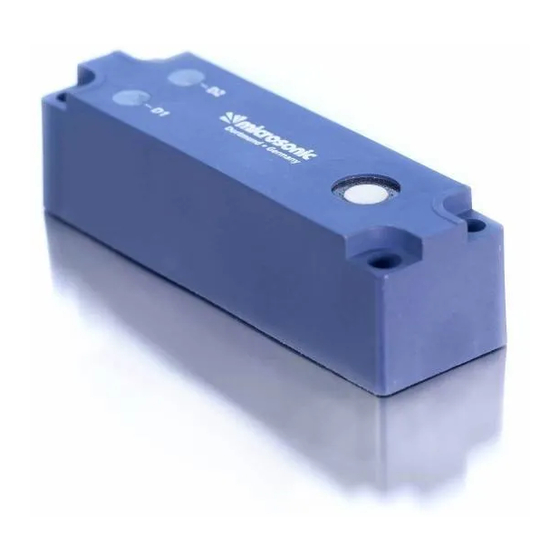
Product description
The lcs-sensor with two switched out-
puts measures the distance to an object
within the detection zone contactless.
Depending on the adjusted detect dis-
tance the switched outputs are set.
The output functions are changeable
from NOC to NCC.
Light
LEDs) indicate the switching status.
The sensors can be trained using Teach-
in processes.
Using the LinkControl adapter (optional
accessory) all sensor parameter settings
may be made by a Windows-Software.
Important instructions for as-
Operating instructions
sembly and application
lcs-Ultrasonic Sensors with
All
employee
two switched outputs
measures must be taken prior to assembly,
start-up, or maintenance work (see operation
manual for the entire plant and the operator
lcs-25/DD/QP
instruction of the plant).
The sensors are not considered as safety
lcs-35/DD/QP
equipment and may not be used to ensure
human or machine safety!
lcs-130/DD/QP
The lcs-sensors indicate a blind zone, in
which the distance cannot be measured. The
operating range indicates the distance of the
Sensor adjustment with Teach-in procedure
1
2
1
Adjust detect point D1
Adjust window mode D1
Place object at position
Place object at position
Connect Com to +U
until both
Connect Com to +U
until both
B
B
LEDs flash simultaneously
LEDs flash simultaneously
(ca. 3 s)
(ca. 3 s)
Both LEDs:
flash
Both LEDs:
flash
mutually
mutually
Place object at position
Beide LEDs:
blinken
wechselseitig
Connect Com to +U
Connect Com to +U
B
B
for about 1 s
for about 1 s
Normal mode operation
Set switched output D1
sensor that can be applied with normal re-
flectors with sufficient function reserve.
When using good reflectors, such as a calm
water surface, the sensor can also be used up
to its maximum range. Objects that strongly
absorb (e.g. plastic foam) or diffusely reflect
sound (e.g. pebble stones) can also reduce
the defined operating range.
emitting
diodes
(three-colour
Assembly instructions
Assemble the sensor at the installation
location.
Plug in the connector cable to the M 12
connector.
and
plant
safety-relevant
1
85 %
Adjust two-way reflectiv
Set NOC/NCC D1
barrier D1
Place reflector at position
Connect Com to +U
until both
Connect Com to +U
until both
B
B
LEDs flash simultaneously
LEDs flash mutually
(ca. 3 s)
(ca. 13 s)
Both LEDs:
flash
LED D1:
on: NOC
mutually
off: NCC
LED D2:
flashes
To change output characteristic
Connect Com to +U
B
connect Com to +U
B
for about 10 s
for about 1 s
Wait for 10 s
2
1
3
5
4
colour
+U
1
brown
B
3
-U
blue
B
4
D2
black
2
D1
white
5
Com.
grey
Fig. 1: Pin assignment with view onto sensor
plug and colour coding of the
microsonic connection cable
Assembly distances
The assembly distances shown in Fig.2 for
two or more sensors should not be fallen
below in order to avoid mutual interference.
>10 cm
>1.0 m
>30 cm
>1.7 m
>60 cm
>5.4 m
Fig. 2: Assembly distances
1
2
1
Adjust detect point D2
Adjust window mode D2
Place object at position
Place object at position
Connect Com to -U
until both
Connect Com to -U
until both
B
B
LEDs flash simultaneously
LEDs flash simultaneously
(ca. 3 s)
(ca. 3 s)
Both LEDs:
flash
Both LEDs:
flash
mutually
mutually
Place object at position
Beide LEDs:
blinken
wechselseitig
Connect Com to -U
Connect Com to -U
B
B
for about 1 s
for about 1 s
Normal mode operation
Set switched output D2
Start-up
lcs sensors are delivered factory made with
the following settings:
Switched outputs on NOC
Detecting distances at operating range
and half operating range
Measurement range set to maximum
range
Set the parameters of the sensor using the
Teach-in procedure.
Operation
lcs- sensors work maintenance free. Small
amounts of dirt on the surface do not influ-
ence function. Thick layers of dirt and caked-
on dirt affect sensor function and therefore
must be removed.
1
85 %
Adjust two-way reflectiv
Set NOC/NCC D2
barrier D2
Place reflector at position
Connect Com to -U
until both
Connect Com to -U
until both
B
B
LEDs flash simultaneously
LEDs flash mutually
(ca. 3 s)
(ca. 13 s)
Both LEDs:
flash
LED D2:
on: NOC
mutually
off: NCC
LED D1:
flashes
To change output characteristic
Connect Com to -U
B
connect Com to -U
B
for about 10 s
for about 1 s
Wait for 10 s
Note
mic+sensors have internal temperature
compensation. Because the sensors heat
up on their own, the temperature com-
pensation reaches its optimum working
point after approx. 30 minutes of opera-
tion.
During normal mode operation, a yel-
low LED signals that the corresponding
switched output has connected.
During Teach-in mode, the hysteresis
loops are set back to factory settings.
If no signal is transmitted to the Com
input for 20 s during parameter setting
mode the made changes are stored and
the sensor returns to normal mode ope-
ration.
You can reset the factory settings at any
time, see »Lock Teach-in & factory set-
.
ting«
lcs-sensors optional can be programmed
using the LinkControl adapter LCA-2,
see «Optional setting of parameters
using the LinkControl Adapter LCA-2».
2014/30/EU
*B7300*
MV-DO-074380-523829
Lock Teach-in & factory setting
Activate/deactivate
Reset to factory
Teach-in
setting
Turn supply voltage OFF
Turn supply voltage OFF
While Com is connected
While Com is connected
to -U
turn on
to -U
turn on
B
B
power suply
power suply
Keep Com connected to
Keep Com connected to
-U
until both LEDs flash
-U
until both LEDs
B
B
simultaneously
stop flashing
(ca. 3 s)
(ca. 13 s)
LED D1:
on: Teach-in
activated
off: Teach-in
deactivated
LED D2:
flashes
To activate or
deactivate Teach-in
connect Com to -U
for
B
about 1 s
Wait for 10 s
Normal mode operation
Advertisement

Subscribe to Our Youtube Channel
Related Manuals for Microsonic lcs-25/DD/QP


Summary of Contents for Microsonic lcs-25/DD/QP
- Page 1 If no signal is transmitted to the Com accessory) all sensor parameter settings Plug in the connector cable to the M 12 microsonic connection cable Teach-in procedure. input for 20 s during parameter setting may be made by a Windows-Software.
- Page 2 50 ms 70 ms 110 ms Response time Time delay before availability < 300 ms < 300 ms < 300 ms Order no. lcs-25/DD/QP lcs-35/DD/QP lcs-130/DD/QP Switched output pnp, U -2 V, I = 200 mA pnp, U -2 V, I...
- Page 3 GmbH / Phoenixseestraße 7 / 44263 Dortmund / Germany / T +49 231 975151-0 / F +49 231 975151-51 / E info@microsonic.de / W microsonic.de The content of this document is subject to technical changes. Specifications in this document are presented in a descriptive way only. They do not warrant any product features.
Need help?
Do you have a question about the lcs-25/DD/QP and is the answer not in the manual?
Questions and answers