Advertisement
Quick Links
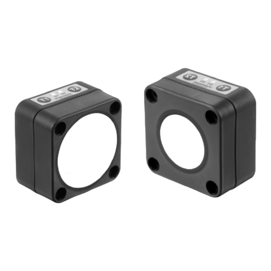
Product description
The lcs+ sensor offers a non-contact
measurement of the distance to an
object which must be positioned
within the sensor's detection zone.
The switched output is set condi-
tional upon the adjusted detect dis-
tance.
Via the Teach-in procedure, the de-
tect distance and operating mode
can be adjusted. One LED indicates
operation and the state of the swit-
Operating manual
ched output.
The lcs+ sensors are IO-Link-capable
Ultrasonic proximity switch with
in accordance with IO-Link specifica-
one switched output and IO-Link
tion V1.0.
interface
Safety instructions
Read the operating instructions
lcs+340/F
lcs+600/F
prior to start-up.
Connection, installation and ad-
Sensor adjustment with Teach-in procedure
Set detect point
Set detect point +8 %
– method A
– method B
Place object at position 1.
Place object at position 1.
Press T2 for about
Press T2 for about
3 s, until both LEDs flash
3 s, until both LEDs flash
simultaneously.
simultaneously.
Both LEDs:
flash alternately
Both LEDs:
flash alternately
Press T2 for about
Press T2 for about 1 s.
3 s, until both LEDs flash
mutually again.
justments may only be carried out
by qualified staff.
No
safety
component
accordance with the EU Machine
Directive.
Use for intended purpose only
lcs+ ultrasonic sensors are used for
non-contact detection of objects.
Installation
Mount the sensor at the place of
fitting.
Connect a connection cable to the
M12 device plug.
Start-up
Connect the power supply.
Carry out sensor adjustment in
accordance with the diagram.
Set two way reflective
Set window mode
barrier
Place reflector at
Place object at position 1.
position 1.
Press T2 for about
Press T2 for about
3 s, until both LEDs flash
3 s, until both LEDs flash
simultaneously.
simultaneously.
Both LEDs:
flash alternately
Both LEDs:
flash alternately
Place object at position 2.
Both LEDs:
flash mutually
Press T2 for about 1 s.
Press T2 for about 10 s.
Normal mode operating
Set switched output
2
1
in
3
5
4
colour
1
+U
brown
B
3
-U
blue
B
4
F
black
2
-
white
5
Sync
grey
Fig. 1: Pin assignment with view onto sensor
plug and colour coding of the
microsonic connection cables
Factory setting
Switched output on NOC.
Detect distance at operating range.
Operating modes
Three operating modes are available
for the switched output:
Activate/deactivate
Set NOC/NCC
Teach-in
Switch off operating
voltage.
While pressing T1 turn on
operating voltage.
Press T2 for about 13 s,
Keep T1 pressed for about
until both LEDs flash
3 s, until both LEDs flash
mutually.
simultaneously.
LED D1:
flashes
LED D2:
flash
LED D2:
on: NOC
LED D1:
on: Teach-in
off: NCC
activated
off: Teach-in
deactivated
To change output
To activate/deactivate
characteristic press T2 for
Teach-in press T1 for
about 1 s.
about 1 s.
Wait for 10 s.
Wait for 10 s
Operation with one detect point
Synchronisation
The switched output is set when the
If under multiple sensor operation
object falls below the set detect
the assembly distance falls below the
point.
values shown in Fig. 2, the internal
Window mode
synchronisation should be used. For
The switched output is set when the
this purpose interconnect each pin 5
object is within the set window.
of max. 10 sensors.
Two-way reflective barrier
The switched output is set when the
Maintenance
object is between sensor and fixed
microsonic sensors are maintenance-
reflector.
free. In case of excess caked-on dirt
we recommend cleaning the white
sensor surface.
Notes
≥ 2,00 m ≥ 18,00 m
≥ 4,00 m ≥ 30,00 m
Fig. 2: Assembly distances
Reset to factory setting
Switch off operating
voltage.
While pressing T1 turn on
operating voltage.
Keep T1 pressed for about
13 s, until both LEDs
flash mutually.
Normal mode operating
Further Settings
The sensors of the lcs+ family have
a blind zone, within which a dis-
tance measurement is not possi-
ble.
The lcs+ sensors are equipped
with an internal temperature com-
pensation. Due to the sensors self
heating, the temperature compen-
sation reaches its optimum work-
ing-point after approx. 30 minutes
of operation.
In the normal operating mode, an il-
luminated yellow LED signals that the
switched
output
is
switched
through.
The lcs+ sensors have a push-pull
switched output.
In the »Two-way reflective barrier«
operating mode, the object has to
be within the range of 0-85 % of
the set distance.
In the »Set detect point – method
A« Teach-in procedure the actual
distance to the object is taught to
the sensor as the detect point. If
the object moves towards the
sensor (e.g. with level control) then
the taught distance is the level at
which the sensor has to switch the
output.
If the object to be scanned moves
into the detection area from the
side, the »Set detect point +8 % –
method B« Teach-in procedure
should be used. In this way the
switching distance is set 8 % fur-
ther than the actual measured dis-
tance to the object. This ensures a
reliable switching distance even if
the height of the objects varies
slightly.
Advertisement

Related Manuals for Microsonic lcs+340/F


Summary of Contents for Microsonic lcs+340/F
- Page 1 The switched output is set when the Maintenance tect distance and operating mode object is between sensor and fixed microsonic sensors are maintenance- Fig. 1: Pin assignment with view onto sensor can be adjusted. One LED indicates Installation reflector.
- Page 2 NFPA 79 applications. microsonic GmbH / Phoenixseestraße 7 / 44263 Dortmund / Germany / T +49 231 975151-0 / F +49 231 975151-51 / E info@microsonic.de / W microsonic.de The content of this document is subject to technical changes. Specifications in this document are presented in a descriptive way only. They do not confirm any product features.
- Page 3 F02 (Average value filter) The size of the detection zone can be strength of the reflected echo. Vendor name 0x10 microsonic GmbH 0x10 microsonic GmbH 0x11 www.microsonic.de 0x11 www.microsonic.de Vendor text Forms the arithmetic mean across varied in three steps.
Need help?
Do you have a question about the lcs+340/F and is the answer not in the manual?
Questions and answers