Table of Contents
Advertisement
Quick Links
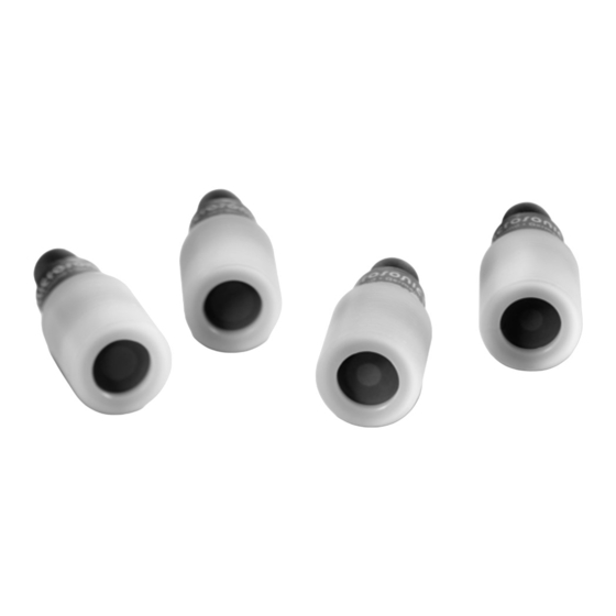
Product description
The pico+ sensor offers a non-contact
measurement of the distance to an
object which must be positioned
within the sensor's detection zone.
The switching output is set conditional
upon the adjusted detect distance.
The ultrasonic transducer surface of
the pico+ sensors is laminated with a
PTFE film. The transducer itself is
sealed against the housing by a joint
ring. This composition permits measu-
rement in up to 0.5 bar over pressure.
Via the Teach-in procedure, the detect
distance and operating mode can be
Operating Manual
adjusted. Two LEDs indicate the state
of the switching output.
Ultrasonic proximity switch with
one switching output and IO-Link
IO-Link
The pico+ sensor is IO-Link-capable in
pico+15/TF/F
accordance with IO-Link specification
pico+25/TF/F
V1.1 and supports Smart Sensor Pro-
pico+35/TF/F
file like Digital Measuring Sensor. The
pico+100/TF/F
Diagram 1: Set sensor parameters via Teach-in procedure
1
1
Set switching point
Set switching point +8 %
– method A
– method B
Place object at position
1
.
Place object at position
Connect Com for about
Connect Com for about
3 s to +U
, until
3 s to +U
, until
B
B
both LEDs flash
both LEDs flash
simultaneously.
simultaneously.
Both LEDs:
flash alternately
Both LEDs:
flash alternately
Connect Com for
Connect Com for
about 3 s to +U
about 1 s to +U
.
until both LEDs
B
flash alternately.
sensor can be monitored and parame-
terised via IO-Link.
Safety Notes
Ԏ
Read the operating manual prior
to start-up.
Ԏ
Connection, installation and ad-
justments may only be carried
out by qualified staff.
Ԏ
No safety component in ac-
cordance with the EU Machine
Directive, use in the area of per-
sonal and machine protection
not permitted.
Proper Use
pico+ ultrasonic sensors are used for
non-contact detection of objects.
Installation
Mount the sensor at the place of
Î
fitting.
For the pico+100/TF/F/A we recom-
mend not to use for mounting the
Set switching output
1
2
85
Set two way
Set window mode
reflective barrier
Place reflector at
1
.
Place object at position
1
.
position
Connect Com for about
Connect Com for about
3 s to +U
, until
3 s to +U
B
both LEDs flash
both LEDs flash
simultaneously.
simultaneously.
Both LEDs:
flash alternately
Both LEDs:
Place object at position
2
.
Both LEDs:
flash alternately
Connect Com for about
Connect Com for
,
10 s to +U
B
about 1 s to +U
.
B
both LEDs stop flashing.
Normal operating mode
first 5 mm of the M22 thread on the
side of the transducer.
Connect a connection cable to the
Î
M12 device plug, see Fig. 1.
2
1
3
5
4
1
+U
3
–U
4
F
2
–
5
Com
Fig. 1: Pin assignment with view onto sensor
plug and colour coding of the microso-
nic connection cables
Start-up
Connect the power supply.
Î
Carry out sensor adjustment in ac-
Î
cordance with Diagram 1.
Factory setting
Ԏ
Detect point operation
Ԏ
Switching output on NOC
1
%
Set NOC/NCC
.
1
Connect Com for about
, until
13 s to +U
, until
B
B
both LEDs flash
alternately.
flash alternately
Green LED:
flashes
Yellow LED:
on:
NOC
off: NCC
To change output
characteristic connect
, until
B
Com for about 1 s
to +U
.
B
Wait for 10 s.
Ԏ
Detect distance at operating range
Ԏ
Input »Com« set to »Teach-in«
Ԏ
Filter at F01
Ԏ
Filter strength at P00
Operating modes
Three operating modes are available
for the switching output:
colour
Ԏ
Operation with one switching
brown
B
point
blue
B
The switching output is set when
black
white
the object falls below the set swit-
grey
ching point.
Ԏ
Window mode
The switching output is set when
the object is within the window li-
mits.
Ԏ
Two-way reflective barrier
The switching output is set when
the object is between sensor and
fixed reflector.
Further settings
Reset to
Switch Teach-in + sync
factory setting
Switch off power supply.
Switch off power supply.
Connect Com to –U
.
Connect Com to –U
B
Switch on power supply.
Switch on power supply.
Keep Com connected to
Keep Com connected to
–U
for about 3 s, until
B
–U
for about 13 s, until
B
both LEDs flash
both LEDs stop flashing.
simultaneously.
Green LED:
flashes
Yellow LED:
on: Teach-in
Disconnect Com from –U
off: Sync
To change operating mode
connect Com for
about 1 s to –U
.
B
Wait for about 10 s.
Normal operating mode
Synchronisation
If the assembly distance of multiple
sensors falls below the values shown
in Fig. 2, the internal synchronisation
should be used (»Sync« must be swit-
ched on, see Diagram 1). For this pur-
pose set the switching output of all
sensors in accordance with Diagram 1.
Finally interconnect each pin 5 of the
sensors to be synchronised.
pico+15...
≥0.25 m
≥1.30 m
pico+25...
≥0.35 m
≥2.50 m
pico+35...
≥0.40 m
≥2.50 m
pico+100...
≥0.70 m
≥4.00 m
Fig. 2: Assembly distances.
Maintenance
microsonic sensors are maintenance-
free. In case of excess caked-on dirt
we recommend cleaning the white
sensor surface.
Notes
Ԏ
The sensors of the pico+ family
have a blind zone, within which a
distance measurement is not possi-
ble.
Ԏ
The pico+ sensors are equipped
with an internal temperature com-
pensation. Due to the sensors self
heating, the temperature compen-
sation reaches its optimum wor-
king-point after approx. 120 se-
.
B
conds of operation.
Ԏ
In the normal operating mode, an
illuminated yellow LED signals that
the switching output is switched
through.
Ԏ
The pico+ sensors have a push-pull
switching output.
Ԏ
In the »Two-way reflective barrier«
operating mode, the object has to
.
be within the range of 0-85 % of
B
the set distance.
Ԏ
In the »Set detect point – method
A« Teach-in procedure the actual
distance to the object is taught to
the sensor as the detect point. If the
object moves towards the sensor
(e.g. with level control) then the
taught distance is the level at which
the sensor has to switch the output
(see Fig. 3).
Advertisement
Table of Contents

Related Manuals for Microsonic pico+15/TF/F


Summary of Contents for Microsonic pico+15/TF/F
- Page 1 Digital Measuring Sensor. The Ԏ Switching output on NOC pico+100/TF/F microsonic sensors are maintenance- free. In case of excess caked-on dirt Diagram 1: Set sensor parameters via Teach-in procedure we recommend cleaning the white sensor surface.
- Page 2 +3 V, I = 100 mA Push-Pull, U –3 V, –U +3 V, I = 100 mA switchable NOC/NCC, short-circuit-proof switchable NOC/NCC, short-circuit-proof switchable NOC/NCC, short-circuit-proof switchable NOC/NCC, short-circuit-proof order no. pico+15/TF/F/A pico+25/TF/F/A pico+35/TF/F/A pico+100/TF/F/A Can be programmed via LinkControl and IO-Link.
- Page 3 22 mm). The values in the table are decimal. *B10097* microsonic GmbH / Phoenixseestraße 7 / 44263 Dortmund / Germany / T +49 231 975151-0 / F +49 231 975151-51 / E info@microsonic.de / W microsonic.de MV-DO-153977-785098 The content of this document is subject to technical changes. Specifications in this document are presented in a descriptive way only. They do not warrant any product features.
Need help?
Do you have a question about the pico+15/TF/F and is the answer not in the manual?
Questions and answers