Advertisement
Quick Links
Product Description
The nano sensor offers a non-contact
measurement of the distance to an
object that has to be present within
the sensor's detection zone. Depen-
ding on the set window limits, a dis-
tance-proportional analogue signal is
output.
The window limits of the analogue
output and its characteristic can be
adjusted with the Teach-in procedure.
A duo-LED indicates operation and the
state of the analogue output.
Proper Use
Operating Manual
nano ultrasonic sensors are used for
non-contact detection of objects.
Ultrasonic sensor
with one analogue output
nano-15/CI
nano-15/CU
nano-24/CI
nano-24/CU
Diagram 1: Set Sensor via Teach-in procedure
1
Set window limits
Place object at position
Connect Teach-in
for about 3 s to +U
until LEDs flashes yellow.
LED: flashes
green/yellow
Place object at position
Connect Teach-in
for about 1 s to +U
Safety Notes
Ԏ
Read the operating manual prior
to start-up.
Ԏ
Connection, installation and ad-
justment works should be carried
out by expert personnel only.
Ԏ
No safety component in ac-
cordance with the EU Machine
Directive, use in the area of per-
sonal and machine protection
not permitted
Installation
Mount the sensor at the installation
Î
site.
Connect a connection cable to the
Î
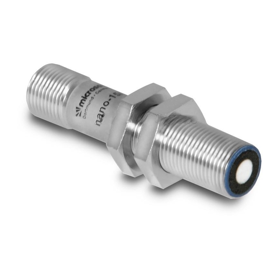
M12 device plug, see Fig. 1.
The assembly distances shown in
Î
Fig. 2 for two or more sensors
should not be fallen below in order
to avoid mutual interference.
Set analogue output
2
Set rising/falling output
characteristic curve
1
.
Connect Teach-in for about
13 s to +U
, until
,
B
B
LED flashes alternately
green/yellow.
LED flashes:
green, green/yellow:
rising
green:
falling
2
.
characteristc
curve
To change
output characteristic
.
connect Teach-in
B
for about 1 s to +U
.
B
Wait for about 10 s.
Normal operating mode
2
1
3
4
colour
nano-15...
1
+U
brown
B
3
–U
blue
B
nano-24
4
I/U
black
2
Teach-in
white
Fig. 2: Minimum mounting distances
Fig. 1: Pin assignment with view onto sensor
Maintenance
plug and colour coding of the microso-
microsonic sensors are maintenance-
nic connection cable
free. In case of excess caked-on dirt
Inbetriebnahme
we recommend cleaning the white
Connect the power supply.
Î
sensor surface.
Adjust the sensor according to Dia-
Î
gram 1.
Factory Setting
Ԏ
Rising analogue characteristic curve
between the blind zone and the
operating range
Further settings
Reset to factory setting
Switch off
operating voltage.
Connect Teach-in to +U
.
B
Switch on
operating voltage.
Keep Teach-in connected
to +U
for about 13 s,
B
until LED flashes
green/yellow alternately.
Disconnect Teach-in
from +U
within 5 s
B
before switching off
power supply.
Normalbetrieb
Notes
Ԏ
Every time the power supply is swit-
ched on, the sensor detects its ac-
tual operating temperature and
≥0.25 m
≥1.30 m
transmits it to the internal tempera-
≥0.25 m
≥1.40 m
ture compensation. This results in a
slight correction of the analogue
output value after 45 seconds.
Ԏ
If the sensor was switched off for at
least 30 minutes and after power
on an object is placed in the middle
of the adjusted analogue window
for 30 minutes (the analogue out-
put value is in the range of 11 to 13
mA or 4.4 to 5.6 V) a new adjust-
ment of the internal temperature
compensation to the actual moun-
ting conditions takes place.
Ԏ
The sensors of the nano family have
a blind zone. Within this zone a di-
stance measurement is not possible.
Ԏ
In the normal operating mode, an
illuminated yellow LED signals the
object is within the adjusted win-
dow limits.
Ԏ
The sensor can be reset to its facto-
ry setting (see »Further settings«).
Advertisement

Related Manuals for Microsonic nano-15/CI


Summary of Contents for Microsonic nano-15/CI
- Page 1 45 seconds. The window limits of the analogue Directive, use in the area of per- plug and colour coding of the microso- microsonic sensors are maintenance- Ԏ If the sensor was switched off for at nic connection cable...
- Page 2 *B10707* microsonic GmbH / Phoenixseestraße 7 / 44263 Dortmund / Germany / T +49 231 975151-0 / F +49 231 975151-51 / E info@microsonic.de / W microsonic.de MV-DO-131213-815844 The content of this document is subject to technical changes. Specifications in this document are presented in a descriptive way only. They do not warrant any product features.
Need help?
Do you have a question about the nano-15/CI and is the answer not in the manual?
Questions and answers