Table of Contents
Advertisement
Quick Links
Product description
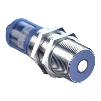
The mic+sensor with one switched output
measures the distance to an object within
Product description
the detection zone contactless. Depen-
ding on the adjusted detect distance the
The mic+sensor with one switched output
measures the distance to an object within
switched output is set.
All settings are done with two push-but-
the detection zone contactless. Depen-
tons
ding on the adjusted detect distance the
Product description
Product description
(TouchControl).
switched output is set.
The mic+sensor with one switched output
The mic+sensor with one switched output
Light emitting diodes (three-colour LEDs)
All settings are done with two push-but-
measures the distance to an object within
measures the distance to an object within
indicate the switching status.
tons
the detection zone contactless. Depen-
the detection zone contactless. Depen-
The output functions are changeable
(TouchControl).
ding on the adjusted detect distance the
ding on the adjusted detect distance the
from NOC to NCC.
Light emitting diodes (three-colour LEDs)
switched output is set.
switched output is set.
indicate the switching status.
The sensors are adjustable manually using
All settings are done with two push-but-
All settings are done with two push-but-
the numerical LED-display or may be trai-
The output functions are changeable
tons
tons
ned using Teach-in processes.
from NOC to NCC.
(TouchControl).
(TouchControl).
The sensors are adjustable manually using
Useful additional functions are set in the
Light emitting diodes (three-colour LEDs)
Light emitting diodes (three-colour LEDs)
Add-on-menu.
the numerical LED-display or may be trai-
indicate the switching status.
indicate the switching status.
Using the LinkControl adapter (optional
ned using Teach-in processes.
Operating manual
The output functions are changeable
The output functions are changeable
Useful additional functions are set in the
accessory) all TouchControl and additio-
from NOC to NCC.
from NOC to NCC.
mic+ Ultrasonic Sensors with
nal sensor parameter settings may be
Add-on-menu.
The sensors are adjustable manually using
The sensors are adjustable manually using
one switched output
Using the LinkControl adapter (optional
made by a Windows-Software.
Operating manual
the numerical LED-display or may be trai-
the numerical LED-display or may be trai-
accessory) all TouchControl and additio-
ned using Teach-in processes.
ned using Teach-in processes.
mic+ Ultrasonic Sensors with
mic+25/D/TC
mic+25/E/TC
nal sensor parameter settings may be
Useful additional functions are set in the
Useful additional functions are set in the
made by a Windows-Software.
one switched output
mic+35/D/TC
mic+35/E/TC
Add-on-menu.
Add-on-menu.
Using the LinkControl adapter (optional
mic+130/D/TC
mic+130/E/TC
Using the LinkControl adapter (optional
Operating manual
mic+25/D/TC
mic+25/E/TC
Operating manual
accessory) all TouchControl and additio-
accessory) all TouchControl and additio-
mic+340/D/TC
mic+340E/TC
mic+ Ultrasonic Sensors with
mic+35/D/TC
mic+ Ultrasonic Sensors with
mic+35/E/TC
Operating manual
nal sensor parameter settings may be
nal sensor parameter settings may be
mic+600/D/TC
mic+600/E/TC
made by a Windows-Software.
made by a Windows-Software.
one switched output
one switched output
mic+ Ultrasonic Sensors with
mic+130/D/TC
mic+130/E/TC
one switched output
mic+340/D/TC
mic+340E/TC
Set sensor parameters alternatively numerically using LED-display...
mic+25/D/TC
mic+25/D/TC
mic+25/E/TC
mic+25/E/TC
mic+25/D/TC
mic+600/D/TC
mic+600/E/TC
mic+35/D/TC
mic+35/D/TC
mic+35/E/TC
mic+35/E/TC
mic+35/D/TC
mic+130/D/TC
mic+130/D/TC
mic+130/E/TC
mic+130/E/TC
mic+130/D/TC
Set sensor parameters alternatively numerically using LED-display...
mic+340/D/TC
mic+340/D/TC
mic+340/D/TC
mic+340E/TC
mic+340E/TC
mic+600/D/TC
mic+600/D/TC
mic+600/E/TC
mic+600/D/TC
mic+600/E/TC
Set sensor parameters alternatively numerically using LED-display...
Set sensor parameters alternatively numerically using LED-display...
Set sensor parameters alternatively numerically using LED-display...
Contact
Sensor Partners BV
James Wattlaan 15
5151 DP Drunen
The Netherlands
+31 (0)416 - 37 82 39
info@sensorpartners.com
sensorpartners.com
Sensor Partners BVBA
Z.1 Researchpark 310
B-1731, Zellik
Belgium
+32 (0)2 - 464 96 90
Set switched output
info@sensorpartners.com
sensorpartners.com
Set switched output
Set switched output
Set switched output
Important instructions for assembly and
application
All employee and plant safety-relevant
measures must be taken prior to assembly,
Important instructions for assembly and
start-up, or maintenance work (see operation
application
All employee and plant safety-relevant
manual for the entire plant and the operator
instruction of the plant).
measures must be taken prior to assembly,
and
a
three-digit
LED-display
start-up, or maintenance work (see operation
Important instructions for assembly and
The sensors are not considered as safety
Important instructions for assembly and
manual for the entire plant and the operator
application
equipment and may not be used to ensure
application
instruction of the plant).
All employee and plant safety-relevant
human or machine safety!
All employee and plant safety-relevant
and
a
three-digit
LED-display
measures must be taken prior to assembly,
The sensors are not considered as safety
measures must be taken prior to assembly,
The mic+ sensors indicate a blind zone, in
start-up, or maintenance work (see operation
equipment and may not be used to ensure
start-up, or maintenance work (see operation
which the distance cannot be measured. The
manual for the entire plant and the operator
Product description
human or machine safety!
manual for the entire plant and the operator
operating range indicates the distance of the
The mic+sensor with one switched output
instruction of the plant).
instruction of the plant).
measures the distance to an object within
The mic+ sensors indicate a blind zone, in
sensor that can be applied with normal re-
and
and
a
a
three-digit
three-digit
LED-display
LED-display
the detection zone contactless. Depen-
The sensors are not considered as safety
flectors with sufficient function reserve.
which the distance cannot be measured. The
The sensors are not considered as safety
ding on the adjusted detect distance the
equipment and may not be used to ensure
operating range indicates the distance of the
When using good reflectors, such as a calm
equipment and may not be used to ensure
switched output is set.
human or machine safety!
water surface, the sensor can also be used up
sensor that can be applied with normal re-
human or machine safety!
All settings are done with two push-but-
to its maximum range. Objects that strongly
tons
and
flectors with sufficient function reserve.
a
three-digit
LED-display
The mic+ sensors indicate a blind zone, in
The mic+ sensors indicate a blind zone, in
(TouchControl).
When using good reflectors, such as a calm
absorb (e.g. plastic foam) or diffusely reflect
which the distance cannot be measured. The
which the distance cannot be measured. The
Light emitting diodes (three-colour LEDs)
sound (e.g. pebble stones) can also reduce
water surface, the sensor can also be used up
indicate the switching status.
operating range indicates the distance of the
operating range indicates the distance of the
the defined operating range.
to its maximum range. Objects that strongly
The output functions are changeable
sensor that can be applied with normal re-
sensor that can be applied with normal re-
absorb (e.g. plastic foam) or diffusely reflect
from NOC to NCC.
flectors with sufficient function reserve.
Synchronisation
flectors with sufficient function reserve.
The sensors are adjustable manually using
sound (e.g. pebble stones) can also reduce
When using good reflectors, such as a calm
the numerical LED-display or may be trai-
If the assembly distances shown in Fig.1 for
When using good reflectors, such as a calm
the defined operating range.
ned using Teach-in processes.
water surface, the sensor can also be used up
two or more sensors are exceeded the inte-
water surface, the sensor can also be used up
Useful additional functions are set in the
to its maximum range. Objects that strongly
grated synchronisation should be used. Con-
Synchronisation
to its maximum range. Objects that strongly
Add-on-menu.
absorb (e.g. plastic foam) or diffusely reflect
nect Sync/Com-channels (pin 5 at the units re-
absorb (e.g. plastic foam) or diffusely reflect
If the assembly distances shown in Fig.1 for
Using the LinkControl adapter (optional
sound (e.g. pebble stones) can also reduce
ceptable) of all sensors (10 maximum).
sound (e.g. pebble stones) can also reduce
accessory) all TouchControl and additio-
two or more sensors are exceeded the inte-
nal sensor parameter settings may be
the defined operating range.
grated synchronisation should be used. Con-
the defined operating range.
made by a Windows-Software.
nect Sync/Com-channels (pin 5 at the units re-
Synchronisation
Synchronisation
ceptable) of all sensors (10 maximum).
mic+25/E/TC
If the assembly distances shown in Fig.1 for
If the assembly distances shown in Fig.1 for
mic+35/E/TC
two or more sensors are exceeded the inte-
two or more sensors are exceeded the inte-
Start here
mic+130/E/TC
grated synchronisation should be used. Con-
grated synchronisation should be used. Con-
mic+340E/TC
nect Sync/Com-channels (pin 5 at the units re-
nect Sync/Com-channels (pin 5 at the units re-
ceptable) of all sensors (10 maximum).
ceptable) of all sensors (10 maximum).
mic+600/E/TC
Start here
Start here
Start here
T1
T1
T1
T1
T1
T1
For single detect
point press T2
T2
until »- - -« is
displayed
T1
T1
For single detect
point press T2
T2
until »- - -« is
displayed
T1
For single detect
For single detect
point press T2
point press T2
T2
T2
until »- - -« is
until »- - -« is
displayed
displayed
T1
Set switched output
T1
T1
T2
T2
Ready
Ready
T2
T2
≥0.35 m
≥0.40 m
≥0.35 m
≥1.10 m
≥0.40 m
≥2.00 m
≥1.10 m
≥4.00 m
≥0.35 m
≥0.35 m
Important instructions for assembly and
≥2.00 m
application
≥0.40 m
≥0.40 m
Fig. 1: Assembly distances, indicating syn-
All employee and plant safety-relevant
≥4.00 m
chronisation/multiplex
measures must be taken prior to assembly,
≥1.10 m
≥1.10 m
start-up, or maintenance work (see operation
manual for the entire plant and the operator
Multiplex mode
Fig. 1: Assembly distances, indicating syn-
≥2.00 m
instruction of the plant).
≥2.00 m
The Add-on-menu allows to assign an indivi-
chronisation/multiplex
The sensors are not considered as safety
dual address »01« to »10« to each sensor
≥4.00 m
≥4.00 m
equipment and may not be used to ensure
connected via the Sync/Com-channel (Pin5).
Multiplex mode
human or machine safety!
The Add-on-menu allows to assign an indivi-
The sensors perform the ultrasonic measure-
Fig. 1: Assembly distances, indicating syn-
The mic+ sensors indicate a blind zone, in
Fig. 1: Assembly distances, indicating syn-
ment sequentially from low to high address.
dual address »01« to »10« to each sensor
which the distance cannot be measured. The
chronisation/multiplex
chronisation/multiplex
Therefore any influence between the sensors
connected via the Sync/Com-channel (Pin5).
operating range indicates the distance of the
The sensors perform the ultrasonic measure-
is rejected.
Fig. 1: Assembly distances, indicating syn-
sensor that can be applied with normal re-
Multiplex mode
Multiplex mode
chronisation/multiplex
flectors with sufficient function reserve.
The address »00« is reserved to synchronisa-
ment sequentially from low to high address.
The Add-on-menu allows to assign an indivi-
The Add-on-menu allows to assign an indivi-
When using good reflectors, such as a calm
Therefore any influence between the sensors
tion mode and deactivates the multiplex
Multiplex mode
water surface, the sensor can also be used up
dual address »01« to »10« to each sensor
dual address »01« to »10« to each sensor
mode. (To use synchronised mode all sensors
is rejected.
The Add-on-menu allows to assign an indivi-
to its maximum range. Objects that strongly
connected via the Sync/Com-channel (Pin5).
connected via the Sync/Com-channel (Pin5).
must be set to address »00«.)
dual address »01« to »10« to each sensor
The address »00« is reserved to synchronisa-
absorb (e.g. plastic foam) or diffusely reflect
The sensors perform the ultrasonic measure-
The sensors perform the ultrasonic measure-
connected via the Sync/Com-channel (Pin5).
sound (e.g. pebble stones) can also reduce
tion mode and deactivates the multiplex
ment sequentially from low to high address.
ment sequentially from low to high address.
The sensors perform the ultrasonic measure-
the defined operating range.
mode. (To use synchronised mode all sensors
ment sequentially from low to high address.
Therefore any influence between the sensors
Therefore any influence between the sensors
must be set to address »00«.)
Synchronisation
Therefore any influence between the sensors
is rejected.
is rejected.
If the assembly distances shown in Fig.1 for
is rejected.
The address »00« is reserved to synchronisa-
The address »00« is reserved to synchronisa-
two or more sensors are exceeded the inte-
The address »00« is reserved to synchronisa-
grated synchronisation should be used. Con-
tion mode and deactivates the multiplex
tion mode and deactivates the multiplex
tion mode and deactivates the multiplex
nect Sync/Com-channels (pin 5 at the units re-
T1 + T2
mode. (To use synchronised mode all sensors
mode. (To use synchronised mode all sensors
mode. (To use synchronised mode all sensors
ceptable) of all sensors (10 maximum).
must be set to address »00«.)
must be set to address »00«.)
must be set to address »00«.)
Press T1 and T2 simultaneously for about
3 s until welcome message has passed
T1 + T2
Start here
Press T1 and T2 simultaneously for about
T1 + T2
3 s until welcome message has passed
T2
T1 + T2
T1 + T2
Press T1 and T2 simultaneously for about
3 s until welcome message has passed
T1 + T2
Press T1 and T2 simultaneously for about
Press T1 and T2 simultaneously for about
T2
3 s until welcome message has passed
3 s until welcome message has passed
T1
Set detect distance in
T2
T2
T1 + T2
mm or cm
T1 + T2
T1 + T2
T2
T2
Set detect distance in
T2
Set detect distance in
mm or cm
T1
T2
mm or cm
For window mode
T1 + T2
T1 + T2
T1 + T2
T1 + T2
operation set far
T2
T1
detect point in
mm or cm
Set detect distance in
For single detect
Set detect distance in
T2
T2
For window mode
point press T2
mm or cm
mm or cm
T2
T1
T2
operation set far
until »- - -« is
T1
T2
displayed
T1 + T2
detect point in
T1 + T2
T1 + T2
mm or cm
T1 + T2
Choose »
« for NCC or
T2
For window mode
For window mode
T1 + T2
»
« for NOC
Choose »
operation set far
« for NCC or
operation set far
T1
T2
T2
T1
T1
T2
»
« for NOC
detect point in
detect point in
mm or cm
Choose »
« for NCC or
mm or cm
T1 + T2
T2
»
T1 + T2
« for NOC
T1 + T2
T1 + T2
T1 + T2
Choose »
« for NCC or
Choose »
« for NCC or
T2
T2
T1
T2
T1
»
« for NOC
»
« for NOC
T1 + T2
T1 + T2
T1 + T2
Ready
T1 + T2
T1
T1 + T2
T1
T1
SENSORPARTNERS.COM
T1 + T2
T1 + T2
Assembly instructions
Assemble the sensor at the installation lo-
cation.
Assembly instructions
Plug in the connector cable to the M 12
connector.
Assemble the sensor at the installation lo-
≥2.50 m
cation.
Plug in the connector cable to the M 12
≥2.50 m
2
1
connector.
≥2.50 m
Assembly instructions
Assembly instructions
≥8.00 m
3
5
4
Assemble the sensor at the installation lo-
Assemble the sensor at the installation lo-
colour
≥2.50 m
cation.
cation.
≥18.00 m
1
+U
brown
2
1
B
Plug in the connector cable to the M 12
Plug in the connector cable to the M 12
3
-U
blue
≥8.00 m
B
3
4
5
≥30.00 m
connector.
connector.
4
D
colour
black
≥2.50 m
≥2.50 m
2
-
white
Assembly instructions
≥18.00 m
1
+U
brown
B
5
Sync/Com.
grey
Assemble the sensor at the installation lo-
≥2.50 m
≥2.50 m
3
-U
blue
B
cation.
≥30.00 m
2
1
2
1
4
D
black
Plug in the connector cable to the M 12
2
-
white
≥8.00 m
≥8.00 m
3
3
5
4
4
connector.
Fig. 2: Pin assignment with view onto sensor
5
colour
≥0.35 m
≥2.50 m
5
Sync/Com.
colour
grey
plug and colour coding of the
≥18.00 m
≥18.00 m
1
1
+U
+U
brown
brown
≥0.40 m
≥2.50 m
B
B
microsonic connection cable
2
1
3
-U
blue
3
-U
blue
B
B
Fig. 2: Pin assignment with view onto sensor
≥30.00 m
≥30.00 m
≥1.10 m
≥8.00 m
4
D
black
4
3
5
4
D
black
colour
Start-up
2
plug and colour coding of the
-
white
2
-
white
≥2.00 m
≥18.00 m
1
+U
brown
5
Sync/Com.
B
grey
mic+ sensors are delivered factory made with
5
microsonic connection cable
Sync/Com.
grey
3
-U
blue
B
≥4.00 m
≥30.00 m
the following settings:
4
D
black
2
-
white
Switched output on NOC
Start-up
5
Sync/Com.
grey
Fig. 2: Pin assignment with view onto sensor
Fig. 2: Pin assignment with view onto sensor
mic+ sensors are delivered factory made with
Detecting distance at operating range
plug and colour coding of the
plug and colour coding of the
and half operating range
the following settings:
Fig. 2: Pin assignment with view onto sensor
microsonic connection cable
microsonic connection cable
Switched output on NOC
Measurement range set to maximum ran-
plug and colour coding of the
ge
Detecting distance at operating range
microsonic connection cable
Start-up
Start-up
and half operating range
mic+ sensors are delivered factory made with
mic+ sensors are delivered factory made with
Start-up
Measurement range set to maximum ran-
the following settings:
the following settings:
mic+ sensors are delivered factory made with
ge
the following settings:
Switched output on NOC
Switched output on NOC
Switched output on NOC
Detecting distance at operating range
Detecting distance at operating range
Detecting distance at operating range
and half operating range
and half operating range
and half operating range
Measurement range set to maximum ran-
Measurement range set to maximum ran-
Measurement range set to maximum ran-
ge
ge
ge
For window mode
operation set far
detect point in
mm or cm
Set the parameters of the sensor manually or
use the Teach-in procedure to adjust the
detect points.
Set the parameters of the sensor manually or
use the Teach-in procedure to adjust the
measuring range
detect points.
c
m
m
m
%
3-digit
LED-display
Set the parameters of the sensor manually or
Set the parameters of the sensor manually or
measuring range
c
m
m
m
%
LED D1 and D2
use the Teach-in procedure to adjust the
use the Teach-in procedure to adjust the
3-digit
detect points.
detect points.
LED-display
Push-buttons T1 and T2
T
1
D
1
D 2 T 2
LED D1 and D2
measuring range
measuring range
Set the parameters of the sensor manually or
c
m
m
m
%
c
m
m
m
%
Fig. 3: TouchControl
Push-buttons T1 and T2
use the Teach-in procedure to adjust the
3-digit
T
1
D
1
D 2 T 2
3-digit
detect points.
LED-display
LED-display
Operation
LED D1 and D2
LED D1 and D2
mic+sensors work maintenance free. Small
Fig. 3: TouchControl
measuring range
c
m
m
m
%
amounts of dirt on the surface do not influ-
3-digit
Push-buttons T1 and T2
ence function. Thick layers of dirt and caked-
Operation
Push-buttons T1 and T2
T
1
D
1
D 2 T 2
LED-display
T
1
D
1
D 2 T 2
on dirt affect sensor function and therefore
mic+sensors work maintenance free. Small
LED D1 and D2
must be removed.
amounts of dirt on the surface do not influ-
Fig. 3: TouchControl
Fig. 3: TouchControl
ence function. Thick layers of dirt and caked-
Push-buttons T1 and T2
T
1
D
1
D 2 T 2
Note
on dirt affect sensor function and therefore
Operation
Operation
mic+sensors have internal temperature
must be removed.
Fig. 3: TouchControl
mic+sensors work maintenance free. Small
mic+sensors work maintenance free. Small
compensation. Because the sensors heat
amounts of dirt on the surface do not influ-
amounts of dirt on the surface do not influ-
Operation
up on their own, the temperature com-
Note
mic+sensors work maintenance free. Small
ence function. Thick layers of dirt and caked-
ence function. Thick layers of dirt and caked-
mic+sensors have internal temperature
pensation reaches its optimum working
amounts of dirt on the surface do not influ-
on dirt affect sensor function and therefore
on dirt affect sensor function and therefore
point after approx. 30 minutes of operati-
compensation. Because the sensors heat
ence function. Thick layers of dirt and caked-
must be removed.
must be removed.
on dirt affect sensor function and therefore
on.
up on their own, the temperature com-
must be removed.
During normal mode operation, a yellow
pensation reaches its optimum working
Note
Note
LED D2 signals that the switched output
point after approx. 30 minutes of operati-
Note
mic+sensors have internal temperature
mic+sensors have internal temperature
has connected.
on.
mic+sensors have internal temperature
compensation. Because the sensors heat
compensation. Because the sensors heat
compensation. Because the sensors heat
During normal mode operation, a yellow
During normal mode operation, the mea-
up on their own, the temperature com-
up on their own, the temperature com-
up on their own, the temperature com-
sured distance value is displayed on the
LED D2 signals that the switched output
pensation reaches its optimum working
pensation reaches its optimum working
pensation reaches its optimum working
LED-indicator in mm (up to 999 mm) or
has connected.
point after approx. 30 minutes of operati-
point after approx. 30 minutes of operati-
point after approx. 30 minutes of operati-
cm (from 100 cm). Scale switches auto-
During normal mode operation, the mea-
on.
on.
on.
matically and is indicated by a point on
During normal mode operation, a yellow
sured distance value is displayed on the
During normal mode operation, a yellow
During normal mode operation, a yellow
LED D2 signals that the switched output
LED-indicator in mm (up to 999 mm) or
top of the digits.
LED D2 signals that the switched output
LED D2 signals that the switched output
has connected.
During Teach-in mode, the hysteresis
cm (from 100 cm). Scale switches auto-
During normal mode operation, the mea-
has connected.
has connected.
loops are set back to factory settings.
matically and is indicated by a point on
sured distance value is displayed on the
During normal mode operation, the mea-
During normal mode operation, the mea-
LED-indicator in mm (up to 999 mm) or
If no objects are placed within the detec-
top of the digits.
sured distance value is displayed on the
sured distance value is displayed on the
cm (from 100 cm). Scale switches auto-
tion zone the LED-indicator shows »- - -«.
During Teach-in mode, the hysteresis
LED-indicator in mm (up to 999 mm) or
LED-indicator in mm (up to 999 mm) or
matically and is indicated by a point on
loops are set back to factory settings.
If no push-buttons are pressed for 20 se-
top of the digits.
cm (from 100 cm). Scale switches auto-
cm (from 100 cm). Scale switches auto-
conds during parameter setting mode the
If no objects are placed within the detec-
During Teach-in mode, the hysteresis
matically and is indicated by a point on
matically and is indicated by a point on
made changes are stored and the sensor
loops are set back to factory settings.
tion zone the LED-indicator shows »- - -«.
top of the digits.
top of the digits.
If no objects are placed within the detec-
returns to normal mode operation.
If no push-buttons are pressed for 20 se-
During Teach-in mode, the hysteresis
During Teach-in mode, the hysteresis
tion zone the LED-indicator shows »- - -«.
You can lock the key pad to provide in-
conds during parameter setting mode the
If no push-buttons are pressed for 20 se-
loops are set back to factory settings.
loops are set back to factory settings.
made changes are stored and the sensor
puts, see »Key lock and factory setting«.
conds during parameter setting mode the
If no objects are placed within the detec-
If no objects are placed within the detec-
You can reset the factory settings at any
returns to normal mode operation.
made changes are stored and the sensor
tion zone the LED-indicator shows »- - -«.
tion zone the LED-indicator shows »- - -«.
returns to normal mode operation.
time, see »Key lock and factory setting«.
You can lock the key pad to provide in-
If no push-buttons are pressed for 20 se-
If no push-buttons are pressed for 20 se-
You can lock the key pad to provide in-
puts, see »Key lock and factory setting«.
conds during parameter setting mode the
puts, see »Key lock and factory setting«.
conds during parameter setting mode the
Show parameters
You can reset the factory settings at any
You can reset the factory settings at any
made changes are stored and the sensor
made changes are stored and the sensor
Tapping push-button T1 shortly during nor-
time, see »Key lock and factory setting«.
time, see »Key lock and factory setting«.
returns to normal mode operation.
returns to normal mode operation.
mal mode operation shows »PAr« on the
You can lock the key pad to provide in-
You can lock the key pad to provide in-
Show parameters
LED-display. Each time you tap push-button
Show parameters
puts, see »Key lock and factory setting«.
Tapping push-button T1 shortly during nor-
puts, see »Key lock and factory setting«.
Tapping push-button T1 shortly during nor-
T1 the actual settings of the switched output
mal mode operation shows »PAr« on the
You can reset the factory settings at any
You can reset the factory settings at any
are shown.
mal mode operation shows »PAr« on the
LED-display. Each time you tap push-button
time, see »Key lock and factory setting«.
time, see »Key lock and factory setting«.
T1 the actual settings of the switched output
LED-display. Each time you tap push-button
are shown.
T1 the actual settings of the switched output
Show parameters
Show parameters
are shown.
Tapping push-button T1 shortly during nor-
Tapping push-button T1 shortly during nor-
mal mode operation shows »PAr« on the
mal mode operation shows »PAr« on the
LED-display. Each time you tap push-button
LED-display. Each time you tap push-button
T1 the actual settings of the switched output
T1 the actual settings of the switched output
2014/30/EU
are shown.
are shown.
2014/30/EU
Enclosure Type 1
Enclosure Type 1
For use only in industrial
2014/30/EU
For use only in industrial
machinery NFPA 79 applications.
machinery NFPA 79 applications.
The proximity switches shall be used with a Lis-
ted (CYJV/7) cable/connector assembly rated mi-
The proximity switches shall be used with a Lis-
Enclosure Type 1
nimum 32 Vdc, minimum 290 mA, in the final in-
ted (CYJV/7) cable/connector assembly rated mi-
For use only in industrial
stallation.
nimum 32 Vdc, minimum 290 mA, in the final in-
machinery NFPA 79 applications.
2014/30/EU
stallation.
2014/30/EU
The proximity switches shall be used with a Lis-
ted (CYJV/7) cable/connector assembly rated mi-
Enclosure Type 1
Enclosure Type 1
nimum 32 Vdc, minimum 290 mA, in the final in-
For use only in industrial
For use only in industrial
stallation.
machinery NFPA 79 applications.
machinery NFPA 79 applications.
The proximity switches shall be used with a Lis-
The proximity switches shall be used with a Lis-
Advertisement
Table of Contents

Related Manuals for Microsonic mic+ Series


Summary of Contents for Microsonic mic+ Series
- Page 1 ≥2.50 m Push-buttons T1 and T2 ned using Teach-in processes. Using the LinkControl adapter (optional The Add-on-menu allows to assign an indivi- microsonic connection cable Operation ence function. Thick layers of dirt and caked- Push-buttons T1 and T2 chronisation/multiplex D 2 T 2 LED-display to its maximum range.
- Page 2 ...or with the Teach-in procedure Key lock and factory setting Activate/deactivate Reset to factory set- TouchControl ting Turn supply voltage Turn supply voltage Adjust two-way reflectiv Set NOC/NCC Adjust detect point Adjust window mode barrier Turn supply voltage While pressing T1 ON while pressing T1 Place object at position Place object at position...
- Page 3 *5395* microsonic GmbH / Phoenixseestraße 7 / 44263 Dortmund / Germany / T +49 231 975151-0 / F +49 231 975151-51 / E info@microsonic.de / W microsonic.de The content of this document is subject to technical changes. Specifications in this document are presented in a descriptive way only. They do not warrant any product features.
Need help?
Do you have a question about the mic+ Series and is the answer not in the manual?
Questions and answers