SonicWALL SonicWave 641, APL67-107 - Access Point Quick Start
- Reference manual (99 pages)
Advertisement
- 1 Introduction
- 2 SonicWave 641 Hardware Overview
- 3 SonicWave 641 Ports
- 4 Checking Package Contents
- 5 Deployment Requirements
- 6 Deployment Considerations
- 7 Installing the Mounting Bracket
- 8 Configuring the Firewall for Wireless Access
- 9 Installing the SonicWave 641
- 10 Verifying SonicWave Operation
- 11 Troubleshooting Tips
- 12 SonicWave 641 LED Activity
- 13 Documents / Resources
Introduction
This SonicWall® SonicWave 641 Quick Start Guide provides instructions for basic installation and configuration of SonicWall SonicWave 641 wireless access points.
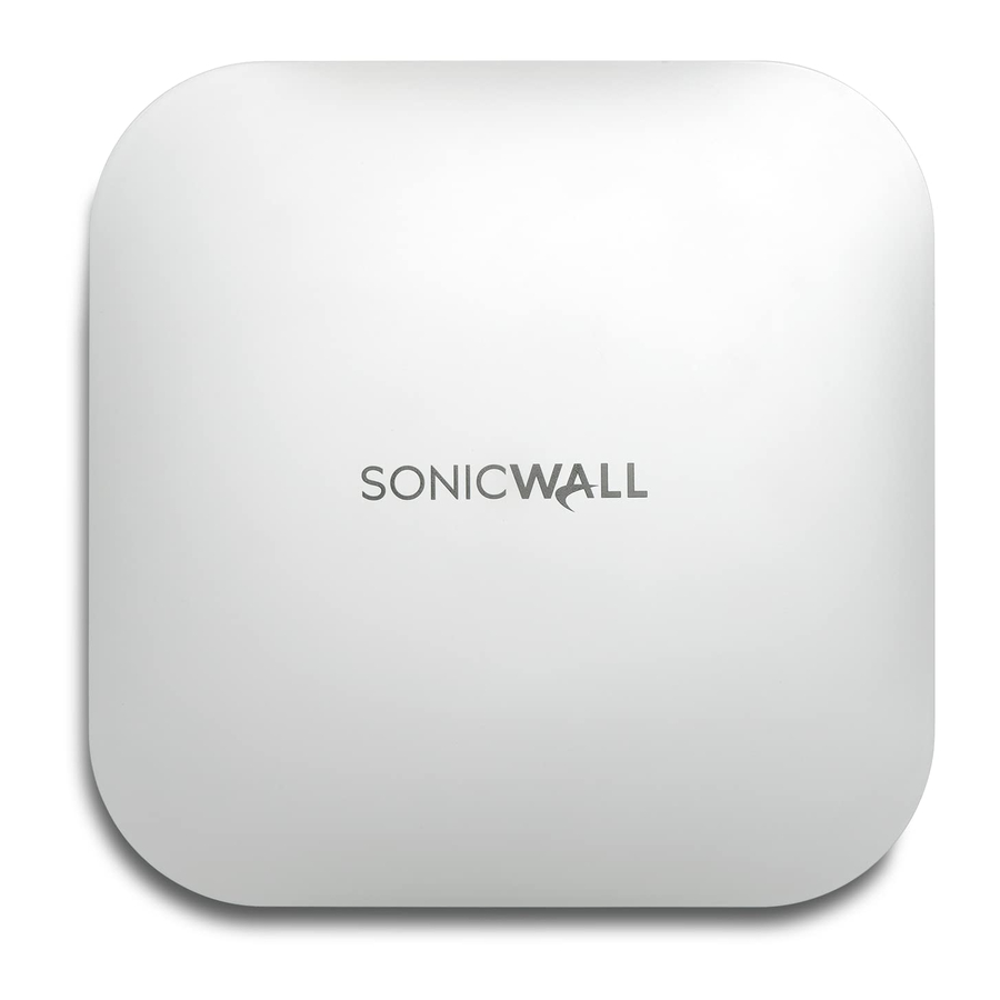
The SonicWall SonicWave 641 is a ceiling-mountable wireless access point suitable for indoor single-unit or multi-unit deployments. It is plenum rated for installation within an enclosed space such as an attic. It can also be mounted on a wall or deployed on a shelf, table, or desktop. Power over Ethernet (PoE) should be provided to power the SonicWave 641.
SonicWave 641 Hardware Overview
SonicWave 641
SonicWave 641 Hardware Components
| 2.4GHz and 5GHz radios | Dual radios provide:
|
| 1GbE LAN port | 1 Ethernet 10/100/1000 LAN port for wired connection to a SonicWall network security appliance |
| USB port | 1 USB 2.0 port |
| Scanning radio | Dedicated third scanning radio |
| Antennas | 5 internal (2.4Ghz x 2 / 5Ghz x 2 / Scan Radio x 1) |
| Power source | 802.3at PoE (standard, PoE device sold separately) Optional DC 12V power adapter, sold separately |
| Chassis | Rectangle 119mm x 214mm x 34mm Plenum rated |
| Kensington security slot | For use with a Kensington locking cable to prevent theft |
| Operating temperature | 0° to 40°C |
SonicWave 641 Ports
The back of the SonicWave 641 provides a LAN/POE port where the PoE Ethernet cable connects the access point with the PoE injector or PoE-enabled switch, which connects to your SonicWall network security appliance.
A 12V power connection is also provided on the back of the unit, where you can plug in a 12V adapter (sold separately) to power the device.
SonicWave 641 Back

When the access point is installed, the back panel is attached to the ceiling or to a wall or other flat surface.
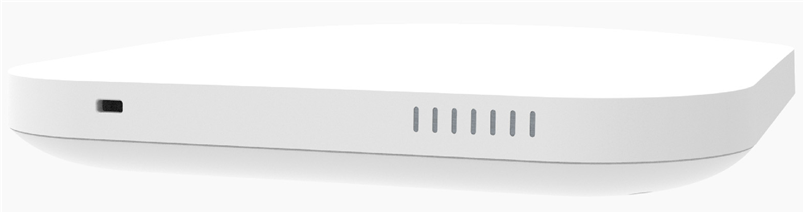
The side panel of the SonicWave 641 has the LED indicators and the USB port.
SonicWave 641 LEDs

You can insert a 3G/4G USB modem into the USB port to create a mobile wireless (MiFi) hotspot. See the SonicOS Administration documentation for information about the MiFi Extender feature. You can also use the USB port with a USB security clamp.
For information about the LEDs, see the SonicWave 641 LED Activitysection.
Checking Package Contents
Before you begin the setup process, verify that your package contains the following items:
- SonicWave 641 appliance
- Mounting plate, screws and anchors
- CAT5e cable
- SonicWall SonicWave 641 Quick Start Guide
- Safety, Environmental, and Regulatory Information document
Package Contents

If any items are missing from the package, contact SonicWall Technical Support at: https://www.SonicWall.com/support/contact-support.
 NOTE: The PoE device for powering the SonicWave 641 is sold separately and is not included in the package.
Deployment Requirements
SonicOS Firmware
SonicWall SonicWave 641 access points are centrally managed by SonicWall network security appliances running the following versions of SonicOS:
- SonicOS 7.1.x or higher
Power Source
Use a 802.3at compliant PoE injector or a PoE enabled switch to provide power to each SonicWave 641.
Internet Connectivity
An active Internet connection is required for your SonicWall network security appliance to download the latest SonicWave 641 firmware.
Gigabit Ethernet Connectivity
The SonicWave 641 requires a 2.5 Gigabit connection to the SonicWall network security appliance to take full advantage of the SonicWave 641 data throughput capability.
Deployment Considerations
Physical placement of the SonicWave 641 wireless access point has a measurable effect on who can and cannot access your wireless signal. If too many users are serviced by a single access point, maximum transfer rates are reached and that access point may become a bottleneck for the whole system.
A site survey can help find the optimum wireless access point placement, but you can find usable locations without it.
RF barriers can be circumvented by deploying multiple access points. Determining how to circumvent RF barriers can be a challenging part of the placement process, but RF barriers can also be used beneficially in an attempt to block signals where you do not want coverage. The 5 GHz frequency is more sensitive to RF barriers. A wall that allows a 2.4 GHz wireless network to operate can block a 5 GHz one.
Common RF Barrier Types
| Barrier Type | RF Signal Blocking |
| Glass, wood, drywall, cube partitions | Low |
| Floors and outer walls, aquariums (brick/marble/granite/water) | Medium |
| Concrete, security glass, wire mesh, stacked books/paper | High |
| Metal partitions, desks, reinforced concrete | Very High |
Access points should be kept clear of Radio Frequency (RF) interference sources. RF interference from home, office, and medical equipment is a common challenge in wireless deployments.
When considering RF interference sources, remember that most cell/wireless phones and Bluetooth devices only utilize the 2.4 GHz frequency. As such, they should not cause significant interference with wireless networks operating in the 5 GHz frequency.
Common Sources of RF Interference
| Interference Source | Possible Range | Bands Affected |
| 2.4 GHz phones | 100 feet | 2.4 GHz (802.11 b/g/n) |
| Bluetooth devices | 30 feet | 2.4 GHz (802.15) |
| Microwave oven | 10 - 20 feet | 2.4 and 5 GHz, depending on shielding |
| Scientific and medical equipment | Short distance, varies | 2.4 and 5 GHz, depending on shielding |
Different frequency bands provide varying signal strength and quality over different distance ranges. Signals in the 2.4 GHz range tend to pass through physical barriers better and carry farther than those in the 5 GHz range, but they do not provide as high a data rate. Signals in the 5 GHz range provide faster data rates for better throughput, but the signal attenuates faster and is best suited for open spaces.
SonicWave 641 Channel Widths, Max Data Rates, Range
| 802.11 (x) | Frequency / MIMO | Channel Width | Max Data Rate | Range (Radius) |
| 802.11a | 5 GHz | 20 MHz | 54 Mbps | 90ft/25m |
| 802.11b | 2.4 GHz | 20 MHz | 11 Mbps | 120ft/35m |
| 802.11g | 2.4 GHz | 20 MHz | 54 Mbps | 120ft/35m |
| 802.11n |
2.4 or 5 GHz MIMO |
20 or 40 MHz | 300 Mbps | 300ft/90m |
| 802.11ac |
5 GHz MU-MIMO |
20 / 40 / 80 MHz | 866 Mbps | 120ft/35m |
To allow multiple separate wireless networks in a shared space, the RF medium is divided into channels. The number of channels is regulated and varies by country. For devices using 5 GHz (802.11a/n/ac), there are up to 23 discrete channels.
For devices using the 2.4 GHz range (802.11b/g/n), the wireless space is limited to a maximum of 13 overlapping channels. As a result of these overlapping channels, 2.4 GHz technology provides only a total of three discrete channels.
Installing the Mounting Bracket
The SonicWave 641 comes with a mounting bracket so it can be mounted on the ceiling or other flat surface. This section describes how to attach the mounting bracket to the ceiling or an indoor wall.
The mounting bracket provides two pairs of T-bar locking tabs that support two ceiling T-bar widths: 15/16 inch and 9/16 inch.
Mounting Bracket Top

Mounting Bracket Bottom

To attach the mounting bracket to the ceiling using T-bar clips:
- Press the top side of the mounting bracket against the ceiling tile T-bar so that the T-bar locking tabs on the mounting bracket are depressed.
- Rotate the mounting bracket so the ceiling T-bar slides into the T-bar clips on the mounting bracket and the T-bar locking tabs click into place.


To attach the mounting bracket to the ceiling or to a wall using screws:
- Place the top side of the mounting bracket against the ceiling or wall and mark the locations for the two screw insertion points.
- Drill starter holes at the marked locations. For a wood wall, use a drill bit that fits the provided screws. For drywall, use a drill bit that fits the anchors.
- For drywall, screw in the anchors.
- Place the mounting bracket against the wall with the holes lined up on the marks or anchors.
- Using the provided screws and a screwdriver, securely attach the mounting bracket to the ceiling or wall.
Configuring the Firewall for Wireless Access
This section provides instructions for configuring SonicOS on your SonicWall network security appliance to connect your SonicWave 641 to the WLAN zone and manage it as a Layer 2 device. This includes:
- Configuring the SonicWave Provisioning Profile for radio frequency, mode, authentication type
- Configuring the Network Interface to which the SonicWave 641 connects
- Configuring the WLAN Zonefor trust, security, and SonicWave provisioning profile
Configuring the SonicWave Provisioning Profile
SonicWave provisioning profiles include all of the settings that can be configured on a SonicWave 641 access point. The profile is then selected when you configure the wireless zone (WLAN by default). When your SonicWave 641 connects to that zone, it is automatically provisioned with the profile settings.
To configure the SonicWave provisioning profile:
- Log into your SonicWall firewall as an administrator (default: admin / password).
- Navigate to the DEVICE | External Controllers | Access Points > Settings page.
- In the Access Point Provisioning Profiles section, do one of the following:
- To modify the default SonicWave profile, click the Edit Profile icon after hovering in the SonicWave row.
- To create a new profile, select SonicWave Profile from the Add New Profile dropdown menu.

The Add/Edit SonicWave Profile dialog displays.
General screen settings:
- Select Enable. This is selected by default.

- To turn on the LEDs for SonicWaves using this provisioning profile, select Enable LED. The LEDs are turned off by default.
- If adding a new profile, type a simple, descriptive name into the Name Prefix field to assist in identifying the SonicWave in this zone. This is the name of the provisioning profile. Each provisioned SonicWave is named with this prefix followed by a unique number. Optionally change the Name Prefix if editing the default SonicWave profile.
- Verify the Country Code for the area of operation.
- Accept the defaults or configure the remaining options as necessary.
Radio Basic Settings:
- Click 5GHz Radio Basic.

- Select Enable Radio. This is selected by default.
- Select a MODE or use the default.
- Type a short, descriptive name into the SSID field. This is the access point name that appears in clients' lists of available wireless connections.
- Under Wireless Security, select the Authentication Type for your wireless network. SonicWall recommends using WPA2 as the authentication type if all client devices support it.
PSK uses a passphrase for authentication, EAP uses an Enterprise RADIUS server. - Select the Cipher Type. When using WPA and WPA2, SonicWall recommends AES for maximum security if all client devices support it.
- Fill in the fields specific to the authentication type that you selected. The remaining fields change depending on the selected authentication type.
- Click 2.4GHz Radio Basic and repeat Step 2 through Step 7.
Radio Advanced Settings:
- Click 5GHz Radio Advanced.

- For most advanced options, the default settings give optimum performance.
- Optionally select the Hide SSID in Beacon checkbox.
The SSID refers to the access point name that appears in clients' lists of available wireless connections. Hiding the SSID provides additional security because it requires the user to know the access point name before connecting. - Click 2.4GHz Radio Advanced and repeat Step 3.
- When finished configuring all options, click OK.
For information about configuring the other options and screens in the Add/Edit SonicWave Profile dialog, see the SonicOS Administration documentation.
Configuring the Network Interface
Each SonicWave or group of SonicWaves must be connected to a physical network interface that is configured in a wireless zone. SonicOS provides a standard wireless zone (WLAN) that can be applied to any available interface.
To configure the network interface in SonicOS:
- Navigate to the NETWORK | System > Interfaces page and click the Edit this interface icon by hovering over the interface to which your SonicWave connects.


- Select WLAN or another (custom) wireless zone from the Zone drop-down menu. The default wireless zone is WLAN.
- Select Static IP Mode for the Mode/IP Assignment.
- In the IP Address field, type in any private IP address that does not interfere with the IP address range of any other interfaces on the appliance. Wireless clients are assigned an IP address in this subnet.
- Enter a Subnet Mask. The default is 255.255.255.0.
- Select a non-zero number for SonicPoint/SonicWave Limit. If 0 is selected, no access points can be discovered on this interface.
- Use the default settings or select appropriate settings for the other fields and click OK.
Configuring the WLAN Zone
To configure the WLAN zone in SonicOS:
- Navigate to OBJECT | Match Objects > Zones page, click the Edit icon in the WLAN row.
- On the General screen, select the Allow Interface Trust option to automate the creation of Access Rules to allow traffic to flow between the interfaces within the zone, regardless of the interfaces to which the zone is applied.
For example, if the WLAN zone has both the X2 and X3 interfaces assigned to it, selecting Allow Interface Trust creates the necessary access rules to allow hosts on these interfaces to communicate with each other.

- Select the checkboxes to enable security services on this zone. Minimally, you would select Enable Gateway Anti-Virus Service, Enable IPS, and Enable Anti-Spyware Service. If your wireless clients are all running SonicWall Client Anti-Virus, select Enable Client AV Enforcement Service.
- In the Guest Services screen, optionally configure guest Internet access. For information about Guest Services, see the SonicOS Administration documentation.
- In the Wireless screen under SonicPoint/SonicWave Settings, select the desired provisioning profile from the SonicWave Provisioning Profile drop-down menu. If you added a new profile in Configuring the SonicWave Provisioning Profile, select it here.
- Select Only allow traffic generated by a SonicPoint/SonicWave to allow only traffic from SonicWall wireless access points to enter the WLAN zone interfaces, providing maximum security.
- When finished, click Save.
You are now ready to connect your SonicWave 641 to your SonicWall network security appliance as described in the following sections.
Installing the SonicWave 641
This section describes how to connect the PoE and network cables and then attach the SonicWave 641 to the mounting bracket.
The SonicWave 641 connects to a WLAN zone interface on your SonicWall network security appliance. The access point is powered through Power over Ethernet (PoE), with the PoE device positioned between the SonicWave 641 and the firewall. SonicWall recommends using CAT5e Ethernet cables to connect the devices.

An 802.3at compliant PoE injector or PoE enabled switch is required to provide power to each SonicWave 641.
To maintain power to the SonicWave 641, the maximum length of CAT5e cable from the PoE device to the SonicWave 641 is 100 meters (333 feet).
To connect the SonicWave 641 to PoE and the network:
- Using an Ethernet cable, connect the Data in port on the PoE Injector to an existing WLAN zone interface on the firewall or to an unused interface to be configured later in SonicOS.
- Using a second Ethernet cable, connect the Data and Power Out port on the PoE injector to the LAN/POE port on your SonicWave 641.
Refer to your PoE Installation Guide for more information. - Plug the power cord of the PoE Injector into an appropriate power outlet.
- Wait up to two minutes for the LAN LED on the SonicWave 641 to illuminate. This indicates an active connection.
To attach the SonicWave 641 to the mounting bracket:
- Line up the two mounting tab insert points on the back of the SonicWave 641 with the mounting tabs on the mounting bracket.
- Insert the mounting tabs into the SonicWave 641 and slide the access point down until the locking tab on the bracket clicks into place on the SonicWave.
Connecting the SonicWave 641

Verifying SonicWave Operation
To verify that the SonicWave is provisioned and operational:
- Log into your SonicWall firewall as an administrator (default: admin / password).
- Navigate to the DEVICE | External Controllers > Access Points > Settings page.
- In the Access Point Objects table, the Status column displays the SonicWave 641 status. It might display Initializing, Updating Firmware, Writing Firmware, and Rebooting. After rebooting, the Status should display Operational.
If the Status displays Operational (Not Licensed) and does not change to Operational soon, contact SonicWall Support for assistance with licensing the SonicWave. - Connect a client device to the SonicWave by selecting the appropriate access point name (SSID).
- Ensure that the client device is not connected to any other network connections (wired LAN, 3G/4G WWAN).
- In a browser, enter https://www.SonicWall.com/; in the address bar and press Enter. The SonicWall website should display. If you are unable to browse to a website, refer to Troubleshooting Tips.
Troubleshooting Tips
When the SonicWave 641 is connected to a SonicWall network security appliance, the two units perform an encrypted exchange, and an entry for the SonicWave 641 is automatically created in the SonicPoint/SonicWave Objects table. Navigate to the DEVICE | External Controllers > Access Points > Settings page in SonicOS. If the entry does not appear in the table within five minutes of connecting the SonicWave 641:
- Make sure the SonicWave 641 is connected to an interface that is configured as part of a wireless zone. Either the default WLAN zone or a custom zone with type set to "wireless" is required.
- Ensure that the SonicWave 641 is properly connected with an Ethernet cable to an 802.3at compliant PoE device.
- If an 802.3at compliant PoE injector is being used, verify that the SonicWave 641 is connected to the PoE port labeled Data & Power Out.
- If the SonicWave 641 has an entry in the table, but reboots frequently or seems nonfunctional:
- Verify that your PoE switch/injector is 802.3at compliant and rated to deliver sufficient power to each PoE port. 802.3af compliant PoE devices do not provide sufficient power to properly run current generation 802.11 devices.
- Click Synchronize Access Points on the DEVICE | External Controllers > Access Points > Settings page to force SonicOS to download a new SonicWave firmware image from the SonicWall back-end server.
If the SonicWave becomes unresponsive or seems erratic, you can use the Reset button to reset the SonicWave to factory default settings or put it into SafeMode. Use a narrow, straight object, like a straightened paper clip to press the Reset button.
- To reboot the SonicWave with factory default settings, press Reset for three seconds until three LEDs begin to flash slowly. If the SonicWave is connected to your firewall, it reboots again after the provisioning profile settings are applied.
- To reboot the SonicWave into SafeMode, press Reset for eight seconds until three LEDs begin flashing at a medium rate.
See the LED Pattern for Reset Button Hold Durations and LED Pattern in SafeMode tables for more information.
TIP: SafeMode allows you to log into the SonicWave directly at 192.168.1.20 (default: admin/password) to manually update the firmware in rare situations when other troubleshooting fails. Contact SonicWall Support for assistance.
SonicWave 641 LED Activity
The SonicWave 641 LEDs provide essential status information about the access point.
Power LED
| LED Color | Description |
| Off | No power |
| Blue | Power is on |
| Security LED | |
| Green | All security services licensed |
| Blinking Yellow |
Security services license expired. Security services monitored by this LED: Gateway Anti-Virus, Intrusion Prevention, AntiSpyware |
Bluetooth Low Energy (BLE) LED
| LED Color | Description |
| Green |
On: Bluetooth has paired successfully. Blinking: Bluetooth is ready for pairing. |
| Off | Bluetooth is not paired. |
| LAN LED | |
| Off | No link |
| Solid Yellow | Link established at 1 Gbps or 2.5 Gbps |
| Blinking Yellow | Active traffic at 1 Gbps |
| Solid Green | Link established at 100 Mbps or 10 Mbps |
| Blinking Green | Active traffic at 100 Mbps or 10 Mbps |
5 GHz Radio LED
| LED Color | Description |
| Off | 5 GHz radio is off |
| Solid Green | 5 GHz radio is on |
| Blinking Green | Active traffic on 5 GHz radio |
| 2.4 GHz Radio LED | |
| Off | 2.4 GHz radio is off |
| Solid Green | 2.4 GHz radio is on |
| Blinking Green | Active traffic on 2.4 GHz radio |
LED Pattern During Firmware or SafeMode Bootup
| LEDs | LED Color | Description |
| LAN | Green - Heartbeat | The three LEDs blink simultaneously in a |
| 5 GHz Radio | Green - Heartbeat | heartbeat pattern while booting is in progress: |
| 2.4 GHz Radio | Green - Heartbeat | On - On - Off |
LED Pattern for Reset Button Hold Durations
| LEDs | LED Color | Description |
| LAN | Blinking Green | The three LEDs blink simultaneously at a slow or medium rate:
|
| 5 GHz Radio | Blinking Green | |
| 2.4 GHz Radio | Blinking Green |
LED Pattern in SafeMode
| LEDs | LED Color | Description |
| LAN | Green - Flow | The three LEDs turn on serially (one by one) and then turn off serially in a flow pattern while the SonicWave 641 is in SafeMode. |
| 5 GHz Radio | Green - Flow | |
| 2.4 GHz Radio | Green - Flow |
NOTE: The LEDs are disabled by default. You can enable them in the SonicWave provisioning profile or individual SonicWave entry in SonicOS on the firewall.
Copyright © 2022 SonicWall Inc. All rights reserved.
SonicWall is a trademark or registered trademark of SonicWall Inc. and/or its affiliates in the U.S.A. and/or other countries. All other trademarks and registered trademarks are property of their respective owners.
The information in this document is provided in connection with SonicWall Inc. and/or its affiliates' products. No license, express or implied, by estoppel or otherwise, to any intellectual property right is granted by this document or in connection with the sale of SonicWall products. EXCEPT AS SET FORTH IN THE TERMS AND CONDITIONS AS SPECIFIED IN THE LICENSE AGREEMENT FOR THIS PRODUCT, SONICWALL AND/OR ITS AFFILIATES ASSUME NO LIABILITY WHATSOEVER AND DISCLAIMS ANY EXPRESS, IMPLIED OR STATUTORY WARRANTY RELATING TO ITS PRODUCTS INCLUDING, BUT NOT LIMITED TO, THE IMPLIED WARRANTY OF MERCHANTABILITY, FITNESS FOR A PARTICULAR PURPOSE, OR NON- INFRINGEMENT. IN NO EVENT SHALL SONICWALL AND/OR ITS AFFILIATES BE LIABLE FOR ANY DIRECT, INDIRECT, CONSEQUENTIAL, PUNITIVE, SPECIAL OR INCIDENTAL DAMAGES (INCLUDING, WITHOUT LIMITATION, DAMAGES FOR LOSS OF PROFITS, BUSINESS INTERRUPTION OR LOSS OF INFORMATION) ARISING OUT OF THE USE OR INABILITY TO USE THIS DOCUMENT, EVEN IF SONICWALL AND/OR ITS AFFILIATES HAVE BEEN ADVISED OF THE POSSIBILITY OF SUCH DAMAGES. SonicWall and/or its affiliates make no representations or warranties with respect to the accuracy or completeness of the contents of this document and reserves the right to make changes to specifications and product descriptions at any time without notice. SonicWall Inc. and/or its affiliates do not make any commitment to update the information contained in this document.
For more information, visit https://www.SonicWall.com/legal/.
Legend

A WARNING icon indicates a potential for property damage, personal injury, or death.
A CAUTION icon indicates potential damage to hardware or loss of data if instructions are not followed.
IMPORTANT, NOTE, TIP, MOBILE, or VIDEO:An information icon indicates supporting information.
To access the Support Portal, go to https://www.SonicWall.com/support.
SonicWave 641 Quick Start Guide
Updated - February 2022
232-005723-50 Rev A

Documents / Resources
References
Contact Support - SonicWall
Next-Gen Firewalls & Cybersecurity Solutions - SonicWall
SonicWall Legal Documents and Notices | Directory
Support Portal & Downloads - SonicWall
Download manual
Here you can download full pdf version of manual, it may contain additional safety instructions, warranty information, FCC rules, etc.
Download SonicWALL SonicWave 641, APL67-107 - Access Point Quick Start
Advertisement


Need help?
Do you have a question about the SonicWave 641 and is the answer not in the manual?
Questions and answers