A l l t r a d e m a r k s , b r a n d n a m e s , a n d b r a n d s a p p e a r i n g h e r e i n a r e t h e p r o p e r t y o f t h e i r r e s p e c t i v e o w n e r s .
• C r i t i c a l a n d e x p e d i t e d s e r v i c e s
• I n s t o c k / R e a d y - t o - s h i p
Artisan Scientific Corporation dba Artisan Technology Group is not an affiliate, representative, or authorized distributor for any manufacturer listed herein.
In Stock
Used and in Excellent Condition
Open Web Page
https://www.artisantg.com/80854-1
• We b u y y o u r e x c e s s , u n d e r u t i l i z e d , a n d i d l e e q u i p me n t
• F u l l - s e r v i c e , i n d e p e n d e n t r e p a i r c e n t e r
Page 1
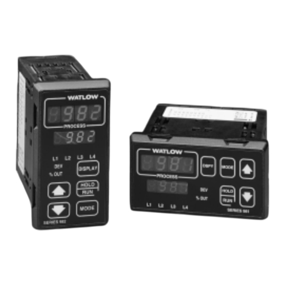
Watlow 981C-10CA-JAGG 1/8 DIN Ramping Controller In Stock Used and in Excellent Condition Open Web Page https://www.artisantg.com/80854-1 A l l t r a d e m a r k s , b r a n d n a m e s , a n d b r a n d s a p p e a r i n g h e r e i n a r e t h e p r o p e r t y o f t h e i r r e s p e c t i v e o w n e r s .
Page 2
ISO 9001 Registered Company Winona, Minnesota USA Watlow Controls 1241 Bundy Boulevard, P.O. Box 5580, Winona, Minnesota USA 55987-5580 Phone: (507) 454-5300, Fax: (507) 452-4507 http://www.watlow.com 0600-0009-0008 Rev R $10.00 January 2007 Made in the U.S.A. Supersedes: 0600-0009-0008 Rev P...
Page 3
About This Manual How to Use this Manual We have designed this user’s manual to be a helpful guide to your new Watlow con- troller. The headlines in the upper right and left corners indicate which tasks are explained on that page. If you are a new user, we suggest that your read through the whole manual.
Page 4
Chapter 1 The Factory Menus Starting Out With the Watlow Series 981/982 6.1 Entering the Factory Menus 1.1 Starting Out With the Watlow Series 981/982 6.2 Diagnostics Menu and Prompts 1.2 Menu Overview 6.7 Calibration Menu and Prompts 1.3 DIP Switch Locations and Functions 1.4 Setting the Hardware Lockout DIP Switch...
Page 5
Notes Contents WATLOW Series 982 User’s Manual...
Page 6
The new controller meets a wide variety of needs in the process industries. Its broad range of I/O options allows control of virtually any process vari- able. In addition to the standard Watlow features, the Series 982 has expanded auto-tuning capabilities and increased alarm functionality.
Page 7
A 0u Restore factory values Oty3 Output 3 module The Series 982 Map. A100 Default prompts Oty4 Output 4 module Test displays dISP tout Test output Starting Out with the Watlow Series 982, Chapter 1 WATLOW Series 982 User’s Manual...
Page 8
Press the release HOLD tabs to remove the controller chassis. MODE SERIES 988 Release Tabs TL W DSPY MODE PROCESS HOLD % OUT SERIES 989 Release Tabs Starting Out with the Watlow Series 982, Chapter 1 WATLOW Series 982 User’s Manual...
Page 9
Left-side View (981 & 983) DIP switches. ↑ ↑ battery backup of Run prompts ↑ ↑ lockout Setup and Factory menus Commu- Input Output Global nications Diagnostics Calibration Starting Out with the Watlow Series 982, Chapter 1 WATLOW Series 982 User’s Manual...
Page 10
Conditioner Power Supply. Figure 1.5c - Output 4 External Signal 98 _ C - _ _ _ _ - _ T _ _ Conditioner Power Supply. Starting Out with the Watlow Series 982, Chapter 1 WATLOW Series 982 User’s Manual...
Page 11
J, K, T, N, C, E, Pt2, D Thermocouple Input Thermocouple Input ↑ ↑ RTD Input 0-20mA or 4-20mA Input Figure 6b - Input DIP Switch ↑ Settings. 0-5V, 1-5V or 0-10V Input Starting Out with the Watlow Series 982, Chapter 1 WATLOW Series 982 User’s Manual...
Page 12
(92mm + 0.8) #60069, die #60070). Figure 2.1 - Series 981 and 0.68" 4.06" 1.77 + 0.02 -0.00 Series 982 (103 mm) (17 mm) (45mm + 0.6) dimensions. Installation and Wiring, Chapter 2 2 . 1 WATLOW Series 982 User’s Manual...
Page 13
Top and Bottom (982 or 984) Adjustable Panel or Side (981 or 983) View Mounting Bracket Figure 2.2 - Side and top view. Release Tabs Mounting Slots Bezel Mounting Collar External Gasket 2 . 2 Installation and Wiring, Chapter 2 WATLOW Series 982 User’s Manual...
Page 14
Make sure the inside gasket is seated properly and not twisted. 7. To release the mounting brackets, loosen the mounting bracket screws and push the brackets forward, then pull it up and out. Installation and Wiring, Chapter 2 2 . 3 WATLOW Series 982 User’s Manual...
Page 15
Maintain isolation between input 1 and input 2 to prevent a ground loop. A ground loop may cause incorrect readings, dashes across the upper dis- play or the display of error codes. 2 . 4 Installation and Wiring, Chapter 2 WATLOW Series 982 User’s Manual...
Page 16
Wiring 0-20 and 4-20mA Process Inputs Certain “transmitters” used in process input applications are producing internal resistor failures in the Watlow Series 988 family of controllers. This is only apparent with the Series 988 family 1/8 DIN units with Process Inputs selected (0-20mA or 4-20mA dc only).
Page 17
Series 92A3-1DJ1-0000 982. Failure to do limit control so could result in such damage, and/or injury or death. high temperature light Figure 2.6 - System wiring example. 2 . 6 Installation and Wiring, Chapter 2 WATLOW Series 982 User’s Manual...
Page 18
˜ NOTE: Sketch in your application on this page or a copy of it. See wiring exam- ples in this chapter. Figure 2.7 - Wiring notes. Installation and Wiring, Chapter 2 2 . 7 WATLOW Series 982 User’s Manual...
Page 19
0-20mA and 4-20mA DIP Switch process wiring to Setting prevent a high in- rush current which could burn out the controller’s 7-ohm resistor. See page 2.5 for recommenda- tions. 2 . 8 Installation and Wiring, Chapter 2 WATLOW Series 982 User’s Manual...
Page 20
14-36VÎ (dc) Event Input 2 on (closed) (Chapter 2 and Appendix); • Sensor installation +5VÎ (dc) (Chapter 2); and Internal Circuitry 1KΩ • Wiring (Chapter 2). 100Ω 4.7KΩ .01µf 1KΩ 750Ω Installation and Wiring, Chapter 2 2 . 9 WATLOW Series 982 User’s Manual...
Page 21
• DIP switch set- tings (Chapter 1); • Sensor match Internal Circuitry (Chapter 2 and Appendix); • Sensor installation (Chapter 2); and • Wiring (Chapter 2). 2 . 1 0 Installation and Wiring, Chapter 2 WATLOW Series 982 User’s Manual...
Page 22
0-5VÎ Î , 1-5VÎ Î and 0-10VÎ Î (DC) Process Figure 2.11d — 98 _ C - _ _ F _ - _ _ _ _ Minimum load impedance: 1KΩ 2 . 1 1 Installation and Wiring, Chapter 2 WATLOW Series 982 User’s Manual...
Page 23
98 _ C - _ _ _ T - _ _ _ _ NOTE: Transmitter 4-20mA out See Chapter 1 for DIP switch location and settings. Input 1 or 2 2 . 1 2 Installation and Wiring, Chapter 2 WATLOW Series 982 User’s Manual...
Page 24
98 _ C - _ _ _ _ - T _ _ _ Transmitter 4-20mA out ˜ Input 1 or 2 NOTE: See Chapter 1 for DIP switch location and settings. Installation and Wiring, Chapter 2 2 . 1 3 WATLOW Series 982 User’s Manual...
Page 25
DIP to input 1. switch information. For data communications wiring refer to Data Communications with the Watlow Series 988 Family of Controllers. 2 . 1 4 Installation and Wiring, Chapter 2 WATLOW Series 982 User’s Manual...
Page 26
Factory (Fcty) prompt appears. begin scrolling. Scrolling is disabled once the keys are released or you reach the top of the menu. Figure 3.1 - Series 982 Keys and Displays. Keys & Displays, Chapter 3 WATLOW Series 982 User’s Manual...
Page 27
When a program is running, the set point is controlled by the program. You can view this set point, but cannot change it while the program is running. You can select the event output status for each step. Keys & Displays, Chapter 3 WATLOW Series 982 User’s Manual...
Page 28
>. Use the Up-arrow > or Down-arrow < key to change the prompt setting. Refer to the Appendix for model number options. For information about communications and the communications prompts, refer to the supple- mental manual Data Communications with the Watlow Series 988 Family of Controllers. TL W PROCESS ❶...
Page 29
[Hunt] *Hunt (page 4.11) one of the prompt values. µ ↓ ↑ ← µ [SHYS] *Slidewire Hysteresis *Prompts may not appear, depending Figure 4.2 - on controller configuration. The Input Menu. Setup Menus, Chapter 4 WATLOW Series 982 User’s Manual...
Page 31
• This affects propbands, alarm set points, process set points, calibration offsets, deadbands and ranges. [dEC1] This prompt appears only if you have set input 1 [`In1] to a process input. Default ↓ [```)] [``)0] [`)00] [)000] [dEC1] [DEC1] [dEC1] [dEC1] Setup Menus, Chapter 4 WATLOW Series 982 User’s Manual...
Page 32
[-200]…[`399] [```n] [``32]…[2372] [```0]…[1300] [```E] [-328]…[1470] [-200]…[`799] (W5) [```C] [``32]…[4200] [```0]…[2316] (W3) [```d] [``32]…[4200] [```0]…[2316] [`Pt2] [``32]…[2543 [```0]…[1395] [`rL1] [`rH1] Range Low 1 and Range High 1 continued on next page. Setup Menus, Chapter 4 WATLOW Series 982 User’s Manual...
Page 33
[``°C] & [`r†d] [-5%5] … [[``)0] … [`5%5] [`C_F] [`In1] [CAL1] [CAL1] [CAL1] (Global Menu) (Input Menu) [-999] … [```0] … [`999] units [CAL1] [CAL1] [CAL1] a process input is selected Setup Menus, Chapter 4 WATLOW Series 982 User’s Manual...
Page 34
• Select a negative value to filter the input signal. • Set the value to [```0] to disable the filter. [Ftr1] This prompt always appears. Default ↓ [`-60] … [```0] … [``60] [Ftr1] [Ftr1] [Ftr1] Setup Menus, Chapter 4 WATLOW Series 982 User’s Manual...
Page 35
[SLiD]. high set point limit for process alarms. Default ↓ NOTE: [```0] … [`rH2] If [SLid] is selected for [`In2], [`Ot2] [`rL2] [`rL2] prompt will not appear. Setup Menus, Chapter 4 WATLOW Series 982 User’s Manual...
Page 36
Write the high-end resistance of the slidewire potentiometer to the range low 2 parameter. [LrnH] This prompt appears only on controllers with [`In2] (Input Menu) set to [SLiD]. Default ↓ [``no] [`YES] [LrnH] [LrnH] Setup Menus, Chapter 4 WATLOW Series 982 User’s Manual...
Page 37
[Hunt] This prompt appears only on controllers with [`In2] (Input Menu) See Chapter 9 for set to [SLiD]. more information on slidewire feed- Default back. ↓ [``)1] … [``!0] … [10)0] [Hunt] [Hunt] [Hunt] 4.10 Setup Menus, Chapter 4 WATLOW Series 982 User’s Manual...
Page 38
[Hunt] [SHYS] [SHYS] turn-on point (close) turn-off point (close) Slidewire Hunt Hysteresis slidewire position set point turn-off point (open) Figure 4.11 - turn-on point (open) Hunt and slidewire inner hysteresis. Setup Menus, Chapter 4 4.11 WATLOW Series 982 User’s Manual...
Page 39
*Prompts may not ↓ appear, depending Figure 4.12 - *Retransmit High Limit on controller config- [ArH] Navigating the µ uration. Output Menu. ↓ ↑ ← µ [ACAL] *Retransmit Calibration Offset 4.12 Setup Menus, Chapter 4 WATLOW Series 982 User’s Manual...
Page 40
• [``CL] select direct action, so that output 1 responds when the input signal is more than the set point. [`Ot1] This prompt always appears. Default ↓ [``Ht] [``CL] [`Ot1] [`Ot1] Setup Menus, Chapter 4 4.13 WATLOW Series 982 User’s Manual...
Page 41
[``°C] & [`r†d] [``)1] … [[``@0] … [`5%5] [`C_F] [`In1] [HYS1] [HYS1] [HYS1] (Global Menu) (Input Menu) [```1] … [```3] … [`999] units [HYS1] [HYS1] [HYS1] a process input is selected 4.14 Setup Menus, Chapter 4 WATLOW Series 982 User’s Manual...
Page 42
[Prc2] This prompt appears only on controllers equipped with output 2 process hardware (98__-___F-____) and with [`Ot2] not set to [``no]. Default ↓ 4-20mA 0-20mA 0-5VÎ 1-5VÎ 0-10VÎ (dc) [4-20] [0-20] [`0-5] [`1-5] [0-10] [Prc2] [Prc2] [Prc2] [Prc2] [Prc2] Setup Menus, Chapter 4 4.15 WATLOW Series 982 User’s Manual...
Page 43
[``)1] … [[``@0] … [`5%5] [``°C] & [`r†d] [`C_F] [`In1] [HYS2] [HYS2] [HYS2] (Global Menu) (Input Menu) [```1] … [```3] … [`999] units [HYS2] [HYS2] [HYS2] a process input is selected 4.16 Setup Menus, Chapter 4 WATLOW Series 982 User’s Manual...
Page 44
[LAt2] This prompt appears only on controllers equipped with output 2 hardware (not 98__-___A-____) and with [`Ot2] set to [`AL2] or [AL2n]. Default ↓ [`nLA] [`LAt] [LAt2] [LAt2] Setup Menus, Chapter 4 4.17 WATLOW Series 982 User’s Manual...
Page 45
[`Ot3] This prompt appears only on controllers equipped with output 3 on alarms. hardware for a relay (98__-____-B___, 98__-____-J___ or 98__-____-K___) or switched dc (98__-____-C___). Default ↓ [`AL3] [AL3n] [Ent3] [``no] [`Ot3] [`Ot3] [`Ot3] [`Ot3] 4.18 Setup Menus, Chapter 4 WATLOW Series 982 User’s Manual...
Page 46
[`AL3] This prompt appears only on controllers equipped with output 3 hardware for a relay (98__-____-B___, 98__-____-J___ or 98__-____-K___) or switched dc (98__-____-C___), and with [`Ot3] set to [`AL3] or [AL3n]. Default ↓ [`Pr1] [`de1] [rAtE] [`AL3] [`AL3] [`AL3] Setup Menus, Chapter 4 4.19 WATLOW Series 982 User’s Manual...
Page 47
[``)1] … [[``@0] … [`5%5] [``°C] & [`r†d] [`C_F] [`In1] [HYS3] [HYS3] [HYS3] (Global Menu) (Input Menu) [```1] … [```3] … [`999] units [HYS3] [HYS3] [HYS3] a process input is selected 4.20 Setup Menus, Chapter 4 WATLOW Series 982 User’s Manual...
Page 48
[SIL3] This prompt appears only on controllers equipped with output 3 hardware for a relay (98__-____-B___, 98__-____-J___ or 98__-____-K___) or switched dc (98__-____-C___) and with [`Ot3] set to [`AL3] or [AL3n]. Default ↓ [`OFF] [``On] [SIL3] [SIL3] Setup Menus, Chapter 4 4.21 WATLOW Series 982 User’s Manual...
Page 49
(98__-____-_B__, 98__-____-_D__ , 98__-____-_E__ or 98__-____-_K__) or switched DC (98__-____-_C__) and [`Ot4] is set to [`AL4] or [AL4n]. Default ↓ [`Pr1] [`dE1] [rAtE] [`AL4] [`AL4] [`AL4] 4.22 Setup Menus, Chapter 4 WATLOW Series 982 User’s Manual...
Page 50
[``°C] [`r†d] & [`C_F] [HYS4] [HYS4] [HYS4] Input 1 or 2 (Global Menu) (see note above) [```1] … [```3] … [`999] units [HYS4] [HYS4] [HYS4] a process input is selected Setup Menus, Chapter 4 4.23 WATLOW Series 982 User’s Manual...
Page 51
[SIL4] This prompt appears only on controllers equipped with output 4 hardware for a relay (98__-____-_B__, 98__-____-_D__ , 98__-____-_E__ or 98__-____-_K__) or switched DC (98__-____-_C__) and with [`Ot4] set to [`AL4] or [AL4n]. Default ↓ [`OFF] [``On] [SIL4] [SIL4] 4.24 Setup Menus, Chapter 4 WATLOW Series 982 User’s Manual...
Page 52
[Prc3] This prompt appears only on controllers equipped with retransmit hardware (98__-____-M___ or 98__-____-N___) and with [Aout] not set to [``no]. Default ↓ 4-20mA 0-20mA 0-5VÎ 1-5VÎ 0-10VÎ (dc) [4-20] [0-20] [`0-5] [`1-5] [0-10] [Prc3] [Prc3] [Prc3] [Prc3] [Prc3] Setup Menus, Chapter 4 4.25 WATLOW Series 982 User’s Manual...
Page 53
[Aout] is set to [Prc1] or [Prc2]. [`ArH] This prompt appears only on controllers equipped with retransmit hardware (98__-____-M___ or 98__-____-N___) and with [Aout] not set to [``no]. [`ArL] … [9999] [`ArH] [`ArH] 4.26 Setup Menus, Chapter 4 WATLOW Series 982 User’s Manual...
Page 54
[ACAL] [ACAL] (Global Menu) [-555] … [[```0] … [`555] [``°C] [`C_F] [ACAL] [ACAL] [ACAL] (Global Menu) [-999] … [```0] … [`999] units [ACAL] [ACAL] [ACAL] a process input is selected Setup Menus, Chapter 4 4.27 WATLOW Series 982 User’s Manual...
Page 55
[PStr] Profile Start µ one of the prompt values. ↓ ↑ ← µ [`LOC] Lockout Figure 4.28 - *Prompts may not appear, depending Navigating the on controller configuration. Global Menu. 4.28 Setup Menus, Chapter 4 WATLOW Series 982 User’s Manual...
Page 56
• Latching alarms [`LAt] must be turned off manually. NOTE: For more informa- [`Err] This prompt always appears. tion on errors, see Chapter 8. Default ↓ [`nLA] [`LAt] [`Err] [`Err] Setup Menus, Chapter 4 4.29 WATLOW Series 982 User’s Manual...
Page 57
• [`WE] can be configured as a waitfor event input. [`Ei1] This prompt always appears. Default ↓ [``no] [`LOC] [`ALr] [`OFF] [Hold] [FIL1] … [FIL4] [AbSP] [PAuS] [`WE] [`Ei1] [`Ei1] [`Ei1] [`Ei1] [`Ei1] [`Ei1] [`Ei1] [`Ei1] [`Ei1] [`Ei1] 4.30 Setup Menus, Chapter 4 WATLOW Series 982 User’s Manual...
Page 58
[AbSP] This prompt appears only on controllers with [`Ei1] or [`Ei2] set to [AbSP]. Default ↓ … [`OFF] value of value of [AbSP] [`rL1] [`rH1] (Input Menu) (Input Menu) Setup Menus, Chapter 4 4.31 WATLOW Series 982 User’s Manual...
Page 59
[`LoP] This prompt always appears. Default ↓ ↓ [-100]%… [`Hip] a heat/cool [`LoP] [`LoP] application [[```0]%… [`Hip] a heat only [`LoP] [`LoP] application [-100]%… [`Hip] a cool only [`LoP] [`LoP] application 4.32 Setup Menus, Chapter 4 WATLOW Series 982 User’s Manual...
Page 60
Select the percentage at which the controller will auto-tune the cur- rent control set point. [AtSP] This prompt always appears. Default ↓ [``50] … [``90] … [`150] % [AtSP] [AtSP] [AtSP] Setup Menus, Chapter 4 4.33 WATLOW Series 982 User’s Manual...
Page 61
↓ [```0] … [`999] [``°F] [`C_F] [`gSd] [`gSd] (Global Menu) [[```0] … [``55] [``°C] [`C_F] [`gSd] [`gSd] (Global Menu) [```0] … [`999] units [`gSd] [`gSd] a process input is selected 4.34 Setup Menus, Chapter 4 WATLOW Series 982 User’s Manual...
Page 62
• If [Hold], [Abrt] or [IdSP] is selected, the lower display alternately flashed [Pout] and the current parameter. Press / to clear it. [Pout] This prompt always appears. Default ↓ [Cont] [HOLd] [Abrt] [IdSP] [rSEt] [Pout] [Pout] [Pout] [Pout] [Pout] Setup Menus, Chapter 4 4.35 WATLOW Series 982 User’s Manual...
Page 63
• If [Pout] is set to [Cont] and [PStr] is set to [Proc], then if power is interrupted the controller will use the current process value as its set point. [PStr] This prompt always appears. Default ↓ [StPt] [Proc] [PStr] [PStr] 4.36 Setup Menus, Chapter 4 WATLOW Series 982 User’s Manual...
Page 64
• [```2] locks out the System, Program, PID and Calibration menus. • [```3] locks out the System, Program, PID and Calibration menus and locks the set point. [`LOC] This prompt always appears. Default ↓ [```0] … [```3] [`LOC] [`LOC] Setup Menus, Chapter 4 4.37 WATLOW Series 982 User’s Manual...
Page 65
988 Family of Controllers for detailed information on communications. ❹ Press the Up-arrow key > or the Down-arrow key < to select one of the prompt values. Figure 4.38 - Navigating the Communications Menu. 4.38 Setup Menus, Chapter 4 WATLOW Series 982 User’s Manual...
Page 66
• Setting [Prot] to [Mod] automatically sets [dAtA] to [``8n]. [dAtA] This prompt appears only on controllers equipped with communi- cations hardware (98__-____-_R__ or 98__-____-_S__ or 98__-____-_U__ ). Default ↓ [``7o] [``7E[] [``8n] [dAtA] [dAtA] [dAtA] Setup Menus, Chapter 4 4.39 WATLOW Series 982 User’s Manual...
Page 67
[Addr] This prompt appears only on controllers equipped with communica- tions hardware for EIA/TIA-485 and EIA/TIA-422 (98__-____-_S__). Default ↓ ↓ [```0] … [``31] [`485] [IntF[ [Addr] [Addr] [```0] … [```9] [`422] [Intf] [Addr] [Addr] 4.40 Setup Menus, Chapter 4 WATLOW Series 982 User’s Manual...
Page 68
• [`485] selects EIA/TIA-485. • [`232] selects EIA/TIA-232. [IntF] This prompt appears only on controllers equipped with communi- cations hardware for EIA/TIA-485 and EIA/TIA-232 (98__-____-_U__). Default ↓ [`232] [`485] [IntF] [IntF] Setup Menus, Chapter 4 4.41 WATLOW Series 982 User’s Manual...
Page 70
7.1 ❷ Press the Up-arrow > key to select one of the TL W Operation menus. PROCESS DISPLAY % OUT HOLD Figure 5.1 - Navigating the MODE SERIES 982 Operation Menus. Operation Menus, Chapter 5 WATLOW Series 982 User’s Manual...
Page 71
*Prompts may not appear, depending ❹ Press the Up-arrow key > to step on controller configuration. through the prompt values. The Down-arrow key < backs through the values. Figure 5.2 - The System Menu. Operation Menus, Chapter 5 WATLOW Series 982 User’s Manual...
Page 72
[Ei2S] This prompt appears only on controllers equipped with event input 2 hardware (98__-_5__-____) and with [`Ei2] (Global Menu) set to some- thing other than [``no] . Default ↓ [OpEn] [CLOS] [Ei2S] [Ei2S] Operation Menus, Chapter 5 WATLOW Series 982 User’s Manual...
Page 73
Sets event output 4 on or off. When a profile is complete or on hold, it holds at its previous state. [Ent4] This prompt appears only when [`Ot4] (Output Menu) set to [Ent4]. Default ↓ [`OFf] [``On] [Ent3] [Ent3] Operation Menus, Chapter 5 WATLOW Series 982 User’s Manual...
Page 74
[A2LO] … … value of value of sensor [`AL2] [A2HI] [`rH1] (Output Menu) (Input Menu) range [`dE1] or [rAtE] [```0] … [`999] … [9999] `AL2] [`AL2] [`AL2] [A2HI] [A2HI] (Output Menu) Operation Menus, Chapter 5 WATLOW Series 982 User’s Manual...
Page 75
[A3LO] … … [`Pr1] value of value of [`AL3] [A3HI] [`rH1] sensor (Output Menu) (Input Menu) range [`dE1] or [rAtE] [```0] … [`999] … [9999] `AL3] [`AL3] [`AL3] [A3HI] [A3HI] (Output Menu) Operation Menus, Chapter 5 WATLOW Series 982 User’s Manual...
Page 76
[A4LO] … … value of value of sensor [`AL4] [A4HI] [`rH1] (Output Menu) (Input Menu) range [`dE1] or [rAtE] [```0] … [`999] … [9999] `AL4] [`AL4] [`AL4] [A4HI] [A4HI] (Output Menu) Operation Menus, Chapter 5 WATLOW Series 982 User’s Manual...
Page 77
Operation-System [`AUt] Auto-tune Initiate an auto-tune. NOTE: [`AUt] This prompt always appears. For more informa- tion on auto-tune see Chapter 8. Default ↓ [`OFF] [`Pid] [`AUt] [`AUt] Operation Menus, Chapter 5 WATLOW Series 982 User’s Manual...
Page 79
[``db] *Dead Band (page 5.17) step through the prompt values. The Down-arrow key < backs through the values. *Prompts may not appear, depending on controller configuration. Figure 5.10 - The PID Menus. 5.10 Operation Menus, Chapter 5 WATLOW Series 982 User’s Manual...
Page 81
[`It1] This prompt appears only if [`dFL] (Calibration Menu) is set to [``S1] and [`Pb1] is not set to [```0]. Default ↓ [`)00] … [9(99] min. / repeat [`It1] [`It1] 5.12 Operation Menus, Chapter 5 WATLOW Series 982 User’s Manual...
Page 82
When set to [`)00], derivative is disabled. [`dE1] This prompt appears only if [`dFL] (Calibration Menu) is set to [``SI] and [`Pb1] is set higher than [```0]. Default ↓ [`)00] … [`(99] min. [`dE1] [`dE1] Operation Menus, Chapter 5 5.13 WATLOW Series 982 User’s Manual...
Page 84
[`)00], integral is disabled. [`It2] This prompt appears only if [`dFL] (Calibration Menu) is set to [``SI] and [`Pb2] is set higher than [```0]. Default ↓ [`)00] … [9(99] min./repeat [`It2] [`It2] Operation Menus, Chapter 5 5.15 WATLOW Series 982 User’s Manual...
Page 85
When set to [`)00], derivative is disabled. [`dE2] This prompt appears only if [`dFL] (Calibration Menu) is set to [``SI] and [`Pb2] is set higher than [```0]. Default ↓ [`)00] … [`(99] min. [`dE2] [`dE2] 5.16 Operation Menus, Chapter 5 WATLOW Series 982 User’s Manual...
Page 86
[db`A] [db`A] (Global Menu) [-555] … [```0] … [`555] [``°C] [`C_F] [db`A] [db`A] [db`A] (Global Menu) [-999] … [```0] … [`999] a process units input is selected [db`A] [db`A] [db`A] Operation Menus, Chapter 5 5.17 WATLOW Series 982 User’s Manual...
Page 88
6.7 Figure 6.1 - Navigating the Factory Menus. TL W PROCESS ❷ Use the Up-arrow key > to select one of the Factory Menus. DISPLAY % OUT HOLD MODE SERIES 982 Factory Menus, Chapter 6 WATLOW Series 982 User’s Manual...
Page 89
In the Diagnostics Menu only the val- µ ues of [dISP] and [tout] can be ↓ [dISP] Test Displays changed. µ ↓ ↑ ← µ [tout] Test Outputs Figure 6.2 - The Diagnostics Menu. Factory Menus, Chapter 6 WATLOW Series 982 User’s Manual...
Page 90
The lower display shows the last four digits of the serial number. [Sn34] [5678] This is what the controller with the serial number 0982345678 would dis- play. [Sn--] This prompt always appears. Factory Menus, Chapter 6 WATLOW Series 982 User’s Manual...
Page 92
• [Proc] process output • [Uret] voltage/retransmit • [Iret] current/retransmit • [SpLy] power supply • [`232] EIA/TIA-232 communications • [`485] EIA/TIA-485 or EIA/TIA-422 communications [Oty1] [Oty2] [Oty3] [Oty4] These prompts always appear. Factory Menus, Chapter 6 WATLOW Series 982 User’s Manual...
Page 93
[`OFF] is selected. If any of the LEDs fail to light contact the factory. [tout] This prompt always appears. Default ↓ [`OFF] [out1] [out2] [out3] [out4] [tout] [tout] [tout] [tout] [tout] Factory Menus, Chapter 6 WATLOW Series 982 User’s Manual...
Page 94
µ ↓ arrow key < to select one of the prompt ↓ values. [2`4`] µ [A`0A] µ ↓ ↓ Refer to Calibrating Watlow Process [2`20] µ Controls for information about the [A`0U] µ ↓ Calibration Menu. ↓ [2`0`] µ [A100] µ...
Page 95
• [``SI] (international) sets the controller to °C; derivative in minutes; proportional band in percent of span; and integral in minutes per repeat. [`dFL] This prompt always appears. Default ↓ [``US] [``sI] [`dFL] [`dFL] Factory Menus, Chapter 6 WATLOW Series 982 User’s Manual...
Page 96
Represents the profile to be edited or viewed. Range: 1 to 4 Default: [StEP] Step: Represents the current step of the profile to be edited or viewed. Range: 1 to 6 Default: 1 then automatic increment Programming, Chapter 7 WATLOW Series 982 User’s Manual...
Page 97
Hidden if: PtYP = ti [Ent3] Event 3: Selects whether Event 3 is on or off. Range: On or OFF Default: Hidden if: Hardware not present or Ot3 = AL3, AL3n or no Programming, Chapter 7 WATLOW Series 982 User’s Manual...
Page 98
Selecting dSbl disables this feature. If time also entered, countdown will not begin until WPr has been satisfied. See Chapter 7. Range: dSbl, rL1 to rH1 Default: dSbL Programming, Chapter 7 WATLOW Series 982 User’s Manual...
Page 99
End step was encountered. When selected as OFF, the control and auxiliary outputs will be disabled and OFF is shown in the lower display. Range: HoLd or OFF Default: HoLd Programming, Chapter 7 WATLOW Series 982 User’s Manual...
Page 100
To Stop a running profile... Press the Hold/Run key once. To Resume a halted profile... Press the Hold/Run key, press the Mode key to advance to the rESU parameter, and press the Hold/Run key. Programming, Chapter 7 WATLOW Series 982 User’s Manual...
Page 101
The event output prompts, Ent3 and Ent4, are not visible under the Operation menu unless your unit has outputs 3 and 4 and you setup Ot3 and Ot4 as events. Programming, Chapter 7 WATLOW Series 982 User’s Manual...
Page 102
Entering a value of (0) disables the Guaranteed Soak Deviation function. Entering a value greater than zero sets up a plus and minus deviation about set point. Jump-loops Set Point Figure 7.7 - Guaranteed Soak Deviation Window around Set Point. Programming, Chapter 7 WATLOW Series 982 User’s Manual...
Page 103
1. Enter the Operation menu by pressing the Mode key until OPEr appears in the lower display. Use the Up or Down key to select Prog in Programming, Chapter 7 WATLOW Series 982 User’s Manual...
Page 104
75° to 100°F Temperature Step 3: (°F) a soak step, Step 1: holds set point initializes at 100°F set point at 75°F Figure 7.9 - Ramp and Soak Profile. Time (seconds) Programming, Chapter 7 WATLOW Series 982 User’s Manual...
Page 105
Step 2 and repeats the profile two more times (Steps 2 - 5). The program then ends and holds the set point and event status of the last step of the profile prior to ending the program. Programming, Chapter 7 7.10 WATLOW Series 982 User’s Manual...
Page 106
Step 1: initializes set point at 75°F Time (seconds Figure 7.11 - Ramp/Soak with Jump-loop. Programming, Chapter 7 7.11 WATLOW Series 982 User’s Manual...
Page 107
(°F) soak step ramps from 100°F to 75°F at 125°F 175° to 100°F Step 6: end program and hold set point 100 110 Time (seconds) Figure 7.12 - Linking Profiles. Programming, Chapter 7 7.12 WATLOW Series 982 User’s Manual...
Page 108
Both waitfor functions (if enabled) must be satisfied before the time entered in the SoAH step is decremented. Programming, Chapter 7 7.13 WATLOW Series 982 User’s Manual...
Page 109
Ent4 LFiL LFiL Step # Step Type Set Point Time Events Values On Off StPt Hour Ent3 Ent4 rAtE SoAH Hour Ent3 Ent4 LFiL LFiL Table 7.14 - Master Step Chart. Programming, Chapter 7 7.14 WATLOW Series 982 User’s Manual...
Page 110
80 minute time span for the 981/982 to successfully complete auto-tune. If this does not happen within the 80 minute time limit, the Series 981/982 chooses PID values based on the 80 minute tuning cycle performed. Tuning, Alarms and Error Codes, Chapter 8 WATLOW Series 982 User’s Manual...
Page 111
See Chapter 9, “Burst Firing,” for more information. However, if a mechanical contactor or solenoid is switching power to the load, a longer cycle time may be desirable to Tuning, Alarms and Error Codes, Chapter 8 WATLOW Series 982 User’s Manual...
Page 112
1. Remove the control from the case. Release the two tabs on one side of the control, then release the two tabs on the opposite side. You may need to rock the bezel back and forth several times to release the chassis. Tuning, Alarms and Error Codes, Chapter 8 WATLOW Series 982 User’s Manual...
Page 113
OtX = ALXn contacts closed contacts open Alarm 2, 3 and/or 4. In Non-alarm Condition OtX = ALX contacts closed contacts open OtX = ALXn contacts open contacts closed Tuning, Alarms and Error Codes, Chapter 8 WATLOW Series 982 User’s Manual...
Page 114
The Input X sensor generated a value lower than that allowed for the range of the sensor, or the A/D circuitry malfunctioned. Enter a valid input. The A/D Tuning, Alarms and Error Codes, Chapter 8 WATLOW Series 982 User’s Manual...
Page 115
• All keys are inactive. • With Er5, all prompts return to default values. Cycle power to the control. If the error is still present contact the factory. Tuning, Alarms and Error Codes, Chapter 8 WATLOW Series 982 User’s Manual...
Page 116
Chapter 9 Software Burst Fire Communications Dead Band Digital Event Input Filter 9.10 Retransmit 9.12 Slidewire Feedback 9.14 Software Features, Chapter 9 WATLOW Series 982 User’s Manual...
Page 117
PID Menu — [Ct1A], [Ct1b], [Ct2A] or [Ct2b]. • Only the 982 and 981 can use the burst fire feature. The low-voltage units (984 and 983) cannot use burst firing. Software Features, Chapter 9 WATLOW Series 982 User’s Manual...
Page 118
4-20mA signal to implement burst-fire fire. control. We have replaced the power control with a Watlow Loyola QPAC with a QCD card that accepts a signal directly from an open-collector out- put of the Series 982. This gives smooth control at a lower overall system cost.
Page 119
Choose which interface your application will use: EIA-232 serial communi- cations (98_C-____-_R__), or EIA-485/EIA-422 serial communications (98_C-____-_S__), or EIA-232/EIA-485 serial communications (98_C-____- _U__. The computer must have a compatible serial port or an appropriate converter must be used. Software Features, Chapter 9 WATLOW Series 982 User’s Manual...
Page 120
The computer periodically interrogates each controller for its process temperature, set point and alarm status. This information is stored on a disk to provide test verification data for the completed prod- ucts. Software Features, Chapter 9 WATLOW Series 982 User’s Manual...
Page 121
The dead band feature is standard on any Series 982 controller with two control outputs. The dead band prompt will appear if the control outputs are configured for heat/cool or cool/heat. Software Features, Chapter 9 WATLOW Series 982 User’s Manual...
Page 122
The engineer started with a dead band of five degrees, but in the process of tuning the system for optimal control, the setting was reduced to two degrees. This made the chamber more energy efficient and reduced wear on the refrigeration system. Software Features, Chapter 9 WATLOW Series 982 User’s Manual...
Page 123
• Abort [AbSP] terminates the currently running program and goes to Abort Set Point. Requirements A single digital event input is standard on all controls. A second digital input is available as an option for input 2 (98_C-_5__-____). Software Features, Chapter 9 WATLOW Series 982 User’s Manual...
Page 124
The operator now has the ability to start a program with the press of a button, and pause or resume it with the flip of a switch. The operator never needs to touch the Series 982. Software Features, Chapter 9 WATLOW Series 982 User’s Manual...
Page 125
Select a negative value to fil- ter the input signal itself. Use this feature with caution, because a large time constant could hide system upsets. Requirements This feature is standard on all Series 982 controllers. Software Features, Chapter 9 9.10 WATLOW Series 982 User’s Manual...
Page 126
To remove this display dithering set the filter time constant [Ftr1] for input 1 to two seconds. This will smooth the display and pro- vide a more realistic reading. Software Features, Chapter 9 9.11 WATLOW Series 982 User’s Manual...
Page 127
Requirements Output 3 is used for the retransmit option. Choose either a milliamp (98_C-____-M___) or a voltage (98_C-____-N___) signal. Select the output range in the Output Menu. Software Features, Chapter 9 9.12 WATLOW Series 982 User’s Manual...
Page 128
The furnace now can provide ramp and soak capabilities for all eight zones, yet reduce system costs and complexity by using a single ramping controller and seven remote-set-point controllers. Software Features, Chapter 9 9.13 WATLOW Series 982 User’s Manual...
Page 129
A slidewire configuration uses at least two inputs and two control outputs. Input 2 must be a slidewire input (98_C-_3__-____). Outputs must be com- patible with the slidewire valve actuators. Software Features, Chapter 9 9.14 WATLOW Series 982 User’s Manual...
Page 130
If your valve opens and closes quickly, try increasing the [Hunt] value. If the valve’s momentum causes it to “coast” after the contact opens, try increasing the {SHyS} value. Software Features, Chapter 9 9.15 WATLOW Series 982 User’s Manual...
Page 132
3 Year Warranty Warranty Returns The Watlow Series 982 is warranted to be free of 1. Call Watlow Customer Service, (507) 454-5300, defects in material and workmanship for 36 months for a Return Material Authorization (RMA) num- after delivery to the first purchaser for use, providing ber before returning any item for repair.
Page 133
— In proportional controllers, the difference Also known as JISC (Japanese Industrial Standards Committee), its function is similar to between set point and actual value after the system sta- Germany’s Deutsche Industrial Norm (DIN). bilizes. Appendix WATLOW Series 982 User’s Manual...
Page 134
For example, if the proportional band is 20° and the process is 10° below set point, the heat proportioned effort is 50 percent. The lower the PB value, the higher the gain. Appendix WATLOW Series 982 User’s Manual...
Page 135
— Action that provides output switching only at or near the zero-voltage crossing points of the ac sine wave. See burst fire. zero switching — See zero cross. Appendix WATLOW Series 982 User’s Manual...
Page 136
Diagnostics Menu 6.2 - 6.6 output 2 4.15 hysteresis 2 4.16 digital event input 1 2.10 output 2 wiring 2.12 hysteresis 3 4.20 digital event input 2 2.9 hysteresis 4 4.23 digital events 9.8 - 9.9 Appendix WATLOW Series 982 User’s Manual...
Page 137
7.5 wastewater treatment 9.13 retransmit 9.12 - 9.13 wiring 2.4 - 2.14 retransmit calibration offset 4.27 wiring 0-20mA and 4-20mA process retransmit high limit 4.26 inputs 2.5 wiring example 2.6 wiring notes 2.7 Appendix WATLOW Series 982 User’s Manual...
Page 138
{Ent3} event output 3 status 5.4 [`Ot4] output 4 4.22 [WPr] waitfor process crossover [Ent4] event 4 7.2, 7.3 [OtY1] output 1 module type 6.5 value 7.3 {Ent4} event output 4 status 5.4 [`Err] error latching 4.29 Appendix WATLOW Series 982 User’s Manual...
Page 139
-328 to 1472°F (-200 to 800°C) • Control outputs: 10Hz. 1° (JIS) -328 to 1166°F (-200 to 630°C) • Alarm outputs: 1Hz. 0.1° (DIN and JIS) • Display: 2Hz. Resolution • Inputs: 16 bits. WATLOW Series 982 User’s Manual Appendix...
Page 140
® is a registered trademark of Littelfuse, Inc. NOTE: User documentation may be available in French, German, Spanish, Italian and Dutch, as well as English. Check Watlow’s website (www.watlow.com/) for availability. Specify language at time of order. Appendix WATLOW Series 982 User’s Manual...
Page 141
Declaration of Conformity Series 981, 982, 983, 984 Watlow Winona, Inc. 1241 Bundy Blvd. Winona, MN 55987 USA Declares that the following product: Designation: Series 981, 982, 983 or 984 Model Numbers: 98 (1, 2, 3 or 4) (Any letter) – (1 or 2) (0, 3 or 5) (B, C, D, E, F or K) (A, B, C, D, E, F, K or T) –...
Need help?
Do you have a question about the 982 Series and is the answer not in the manual?
Questions and answers