Table of Contents
Advertisement
Quick Links
EM34
D
X
EVELOPMENT
Contents
1
About This Guide ............................................................................................................................................ 4
1.1
Purpose ................................................................................................................................................... 4
1.2
Audience .................................................................................................................................................. 4
1.3
Documentation Conventions..................................................................................................................... 4
2
Introducing the EM34x Development Kit .......................................................................................................... 4
2.1
Overview .................................................................................................................................................. 4
2.2
Development Kit Contents ........................................................................................................................ 5
2.3
Hardware Requirements .......................................................................................................................... 5
2.4
Software Requirements ............................................................................................................................ 5
2.5
Hardware ................................................................................................................................................. 5
2.6
Software .................................................................................................................................................. 6
2.7
Documentation ......................................................................................................................................... 6
2.8
Before You Begin ..................................................................................................................................... 7
3
Development Kit Components ......................................................................................................................... 7
3.1
Overview .................................................................................................................................................. 7
3.2
Hardware ................................................................................................................................................. 8
3.2.1
EM341 Remote Control ..................................................................................................................... 8
3.2.2
EM35x Breakout Board ....................................................................................................................10
3.2.3
EM34x Modules ...............................................................................................................................11
3.2.4
Debug Adapter (ISA3) ......................................................................................................................12
3.3
Acceptable Power Sources for Normal Operation ....................................................................................12
3.3.1
USB Power Supply with Adapters .....................................................................................................13
3.4
Software .................................................................................................................................................13
3.4.1
Network Stack ..................................................................................................................................13
3.4.2
Hardware Abstraction Layer .............................................................................................................13
3.4.3
Sample Applications .........................................................................................................................14
3.4.4
Ember Desktop ................................................................................................................................15
4
Setting up Hardware Components ..................................................................................................................16
4.1
Overview .................................................................................................................................................16
4.2
EM34x Radio Communications Module (RCM) ........................................................................................16
Rev 0.1
K
U
'
IT
SER
S
Copyright © 2015 by Silicon Laboratories
G
UIDE
UG113
UG113
Advertisement
Table of Contents

Related Manuals for Silicon Laboratories EM34 Series


Summary of Contents for Silicon Laboratories EM34 Series
-
Page 1: Table Of Contents
Software ..............................13 3.4.1 Network Stack ..........................13 3.4.2 Hardware Abstraction Layer ......................13 3.4.3 Sample Applications .........................14 3.4.4 Ember Desktop ..........................15 Setting up Hardware Components ........................16 Overview ..............................16 EM34x Radio Communications Module (RCM) ..................16 Rev 0.1 Copyright © 2015 by Silicon Laboratories UG113... - Page 2 UG113 Hardware Connections ..........................16 Connecting the Breakout Board and RCM ....................17 Breakout Board Power Configurations .....................17 Breakout Board Serial Configurations ......................19 Common Hardware Configurations ......................19 Connecting the RF Cable to the RCM ......................24 Installing the Software ............................25 Overview ..............................25 Installing the Ember Stack ........................25 Installing Ember Desktop.........................25 Installing IAR Embedded Workbench for ARM ..................25 Installing the Debug Adapter (ISA3) Utilities ....................25...
- Page 3 UG113 7.3.11 usbaddr ............................32 7.3.12 version .............................32 Software Tools Overview..........................33 Running the remote control sample application..................33 Programming your Application on the EM34x ..................35 Programming Manufacturing Tokens .......................36 8.3.1 Programming Certificates & Installation Codes .................36 Using the Debugger in IAR Embedded Workbench with an Ember Debug Adapter (ISA3) .......36 Rev.
-
Page 4: About This Guide
UG113 1 About This Guide Purpose This document describes the EM34x Development Kit and explains how to set up its hardware and use the Ember Debug Adapter (ISA3). For information on developing and debugging applications with Ember Desktop, see its on- line HTML help. -
Page 5: Development Kit Contents
UG113 the test environment. The Breakout Board provides a direct connection for debugging customer-designed hardware, while the remote control provides a low cost, form factor reference design. For detailed information about the EM35x Breakout Board, see document TS6, EM35xx Breakout Board Technical Specification. Development Kit Contents Table 1 summarizes the components and the specified count for each component in the EM34x Development Kit. -
Page 6: Software
UG113 • Debug Adapter (ISA3) connects a Breakout Board to the Ethernet. The adapter transmits network data collected through its Packet Trace Port and conveys it over its Ethernet connection to Ember Desktop. It also picks up any messages or new software that is addressed to the Breakout Board. The Packet Trace Port is a cabled communication link between the Debug Adapter (ISA3) and the EM34x Module mounted on the Breakout Board. -
Page 7: Before You Begin
UG113 Before You Begin The EM34x Development Kit is designed only for the operating conditions and interfaces specified in documents TS7, Debug Adapter (ISA3) Technical Specification, TS6, EM35x Breakout Board Technical Specification, and TS8, EM3xx Module Technical Specification. Any modifications or alterations to the hardware are liable to cause irreparable damage to the EM34x Development Kit, and shall render its warranty null and void. -
Page 8: Hardware
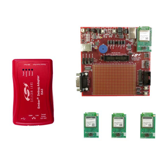
UG113 Hardware The EM34x Series Development Kit development board set has four major hardware components: • EM341 Remote Control • EM35x Breakout Board • EM34x Modules • Debug Adapter (ISA3) The EM34x Series Development Kit also includes the following components: •... - Page 9 UG113 Figure 2. Remote Control For information about the Remote Control, see the reference design files at http://www.silabs.com/products/wireless/zigbee/Pages/zigbee-reference-designs.aspx Rev. 0.1...
-
Page 10: Em35X Breakout Board
UG113 3.2.2 EM35x Breakout Board Figure 3. EM35x Breakout Board The Breakout Board (Figure 3) has the following components: • External power supply connectors • One DB-9 serial port connector for RS-232 serial communication • One USB connector for EM35x SC1 virtual COM port serial communication •... -
Page 11: Em34X Modules
UG113 3.2.3 EM34x Modules The EM34x Series Development Kit Module pictured in Figure 4 is used together with the Development Kit Breakout Board to prototype customer hardware, and to develop and debug application software. Its low-power design represents a good starting point for your own product design. EM34x Module Figure 4. -
Page 12: Debug Adapter (Isa3)
UG113 3.2.4 Debug Adapter (ISA3) The Debug Adapter (ISA3) provides an efficient and configurable debug interface to the Development Kit Breakout Board for processing emulation and debug commands. It also provides an interface to Ember Desktop for monitoring and managing network data. The Debug Adapter (ISA3) has the following components: •... -
Page 13: Usb Power Supply With Adapters
UG113 3.3.1 USB Power Supply with Adapters The USB power adapter (Figure 5) is a linear regulated wall plug power supply with 5 V dc at 1 A regulated output. It has a USB type-B connector for connecting power via a USB cable to the USB port of the Debug Adapter (ISA3) or Breakout Board. -
Page 14: Sample Applications
UG113 3.4.3 Sample Applications The Ember ZNET ZRC software contains sample applications. These demonstrate aspects of the ZRC stac kbased on the ZRC 2.0 specification. Silicon Labs provides an IAR project and workspace file for each application as well as a S.37 binary file. Table 4 lists the sample applications that are in the current distribution. All applications are in directory. -
Page 15: Ember Desktop
UG113 3.4.4 Ember Desktop Ember Desktop is a graphical tool incorporating a Network Analyzer utility that manages the Development Kit hardware and displays network and node activity in real time (see Figure 6). It provides a rich and flexible interface to Ember-embedded networks, which helps you develop and debug new network applications. -
Page 16: Setting Up Hardware Components
UG113 4 Setting up Hardware Components Overview This chapter contains the following sections: • EM34x Radio Communications Module (RCM) • Hardware Connections • Connecting the Breakout Board and RCM • Breakout Board Power Configurations • Breakout Board Serial Configurations • Common Hardware Configurations •... -
Page 17: Connecting The Breakout Board And Rcm
UG113 Connecting the Breakout Board and RCM Refer to document EM34x Quick Start Guide, included in your development kit for detailed step-by-step instructions for setting up your hardware. CAUTION: Observe electrostatic discharge (ESD) precautions when removing, handling, or replacing RF communication modules. - Page 18 UG113 horizontal position, connecting V_ISA to the center pin. The V_ISA LED (DS3) will illuminate when power is applied. Figure 5. Breakout Board Power Supplied by Debug Adapter (ISA3) • Breakout Board Power Supplied by USB (Figure 9): The Breakout Board may also be powered through the USB connector (J5), either using a USB cable plugged in to the USB power adapter included in the development kit, or by connecting it to your PC.
-
Page 19: Breakout Board Serial Configurations
UG113 supply) and J32 (ground). The power supply jumper on the Breakout Board should be in the lower vertical position, connecting V_REG to the center pin. The VIN LED (DS1) will illuminate when power is applied. When powering the Breakout Board in this way, ensure the power switch on the Debug Adapter (ISA3) is in the EXT (External) position. - Page 20 UG113 Figure 8. Debug Adapter (ISA3) Supplying Power; Pass-through UART Being Used for Serial Communication Rev. 0.1...
- Page 21 UG113 Figure 9. Debug Adapter (ISA3) Connecting Packet Trace to Remote Control for programming Rev. 0.1...
- Page 22 UG113 Figure 10. Power Supplied Via USB Connector; Pass-through UART Being Used for Communication Rev. 0.1...
- Page 23 UG113 Figure 11. Debug Adapter (ISA3) Supplying Power; FTDI Serial <-> USB Converter Used for Communication Rev. 0.1...
-
Page 24: Connecting The Rf Cable To The Rcm
UG113 Connecting the RF Cable to the RCM As detailed in Table 5, depending on the configuration of the module, some RCMs include a PCB antenna while others include an RF connector (type U.FL) where an external antenna can be connected via an RF adapter cable. See Figure 18 for an example of a module with a PCB antenna. -
Page 25: Installing The Software
UG113 5 Installing the Software Overview Ember software for the EM34x platform is distributed through Silicon Labs’ support portal at www.silabs.com/zigbee-support. You must contact Customer Support for a portal username. Installing the Ember Stack The Ember Stack installer, ember-stack-<version>-em35x-dev.exe, should be installed first. It performs the following actions: 1. -
Page 26: Installing Ftdi Usb Drivers
UG113 Installing FTDI USB Drivers To use the FTDI USB interface of the Breakout Board for UART connectivity, you must install the drivers for the FTDI USB<->Serial converter. You can obtain this driver from FTDI at http://www.ftdichip.com/Drivers/VCP.htm. These drivers are not required if you connect to the UART of the Breakout Board using the RS-232 port or via the pass-through UART functionality of the Debug Adapter (ISA3). -
Page 27: Ethernet Settings
UG113 Table 6 using either Ember Desktop or a terminal application (for example, Microsoft Telnet Client, HyperTerminal, or PuTTY). Table 5. Debug Adapter (ISA3) Ports Port 4900 Virtual serial port on EM35x via Packet Trace Port cable. 4901 Physical serial port on EM35x via Data Emulation Interface cable. 4902 or 23 Admin interface. -
Page 28: Using The Serial Ports
UG113 Using the Serial Ports Connect to port 4900 or 4901 on the Debug Adapter (ISA3) using either Ember Desktop or a terminal application. Port 4900 connects to the virtual serial port on the EM35x via the Packet Trace Port cable. The virtual serial port has no baud rate or other settings. -
Page 29: Debug Adapter (Isa3) Commands
UG113 7 Debug Adapter (ISA3) Commands Syntax Conventions Element Meaning Example A command or argument that is entered exactly as shown. hostname read Literal An argument that is entered as the desired value for that Variable hostname set hostname variable. An argument chosen from a list. -
Page 30: Debug
UG113 7.3.2 debug debug [on|off|disable] Description Turns BackChannel Debug on (the default), off (for sleepy devices), or disable (for read-protected devices). With no arguments specified, it prints the current debug status. Examples debug debug off debug disable 7.3.3 config config Description Displays the configuration of the Debug Adapter (ISA3): •... -
Page 31: Hostname
UG113 7.3.6 hostname hostname set hostname hostname read Description Sets or displays the hostname of the Debug Adapter (ISA3). The Debug Adapter (ISA3) must be reset for a change to take effect. You can also view the hostname using Ember Desktop. Example hostname set mydevice3 7.3.7 ip... -
Page 32: Reset
UG113 7.3.10 reset reset reset adapter reset host [hold] Description Resets the attached EM35x device if no arguments are specified Resets the Debug Adapter (ISA3) when “adapter” argument is specified. Resets the host MCU (if using the EM35x NCP Host Breakout Board and DEI cable is connected to ISA3), optionally holding the host MCU in reset state if “hold”... -
Page 33: Software Tools Overview
UG113 8 Software Tools Overview Running the remote control sample application There are sample applications for both the remote control (ZRC Controller) and the EM35x breakout board (ZRC Target). The sample applications demonstrate basic RF4CE network and ZRC application functionality. The remote application acts as a generic remote control while the EM35x breakout board acts as a target device. - Page 34 UG113 h. Click Bootloader; browse to <znet-install-directory>\tool\bootloader-em341\app-bootloader\; select app-bootloader.s37. Click on the Erase chip option and click OK. Wait until application upload is done and click OK on the dialog box when complete. k. Unplug the Packet Trace cable from the remote control and replace the battery cover. 4.
-
Page 35: Programming Your Application On The Em34X
UG113 Programming your Application on the EM34x Programming EM34x flash is accomplished with the em3xx_load.exe utility, either via the Windows Command Prompt or via the Upload Application action in Ember Desktop’s Adapters view. The em3xx_load utility is included as part of the Debug Adapter (ISA3) Utilities Installer, in the “bin” subdirectory. A complete summary of em3xx_load functionality with brief descriptions of each option can be found in em3xx_load's own help menu. -
Page 36: Programming Manufacturing Tokens
UG113 Programming Manufacturing Tokens The em3xx_load utility has the ability to program manufacturing tokens. In the case of the EM34x, these tokens are contained in the Customer Information Block (CIB). For more information on using the em3xx_load utility, refer to document UG107, EM35xx Utilities Guide. - Page 37 Silicon Laboratories products are not designed, intended, or authorized for use in applications intended to support or sustain life, or for any other application in which the failure of the Silicon Laboratories product could create a situation where personal injury or death may occur.
Need help?
Do you have a question about the EM34 Series and is the answer not in the manual?
Questions and answers