Table of Contents
Advertisement
Quick Links
Advertisement
Table of Contents

Related Manuals for Silicon Laboratories Telegesis ETRX357DVK


Summary of Contents for Silicon Laboratories Telegesis ETRX357DVK
- Page 1 Telegesis™ TG-ETRX357DVK-PM-012-112 ETRX357DVK Development Kit Product Manual 1.12 Telegesis™ is a trademark of Silicon Laboratories Inc. ETRX357DVK – TELEGESIS DEVELOPMENT KIT FOR ZIGBEE ® TECHNOLOGY PRODUCT MANUAL ©2016 Silicon Labs ETRX357DVK Product Manual (Rev 1.12)
-
Page 2: Etrx357Dvk - Development Kit Functional Summary
ETRX357 Development Kit 1 ETRX357DVK – Development Kit Functional Summary Telegesis ETRX357-DVK development kit is an ideal starting point for development and evaluation of the ETRX357 series low power 2.4GHz ZigBee modules. The ETRX357 modules are based on the third generation Silicon Labs EM357 chipset offering the industry’s highest wireless networking performance and application code space at the lowest... -
Page 3: Table Of Contents
ETRX357 Development Kit Table of Contents ETRX357DVK – DEVELOPMENT KIT FUNCTIONAL SUMMARY ........2 ABSOLUTE MAXIMUM RATINGS OF THE DEVBOARD ..........4 OPERATING CONDITIONS OF THE DEVBOARD ............. 4 ELECTRICAL SPECIFICATIONS ..................4 Power supplies ......................... 4 ZigBee modules ....................... 4 INTEROPERABILITY ...................... -
Page 4: Absolute Maximum Ratings Of The Devboard
ETRX357 Development Kit 2 Absolute Maximum Ratings of the Devboard Parameter Min. Max. Units Condition Supply Voltage V -0.3 Voltage on any I/O pin -0.3 Storage Temperature range °C Without batteries inserted Table 1: Absolute Maximum Ratings The absolute maximum ratings given above should under no circumstances be violated. Stress exceeding one or more of the limiting values may cause permanent damage to the device. -
Page 5: Interoperability
ETRX357 Development Kit 5 Interoperability Unless otherwise specified the Development kits ships with Telegesis R3xx firmware based on EmberZNet4.x. Please note that the R3xx Telegesis AT-Command line interpreter is based on ZigBee PRO, but most of the functionality is implemented as a private application profile. Interoperability with wireless mesh networking solutions from other manufacturers is only possible when knowing the application profile specification of this device and using the provided transparent commands. -
Page 6: The Development Board
ETRX357 Development Kit 6.1 The Development Board Figure 1. The development board The development board which is part of the development kit hosts a USB to serial bridge as well as voltage regulation circuitry. Furthermore it hosts a reset switch, a bootloader switch, 4 buttons, 2 LEDs and a beeper, all of are connected to the I/Os of the module as described later in this document. -
Page 7: What's In The Etrx357Dvk Box
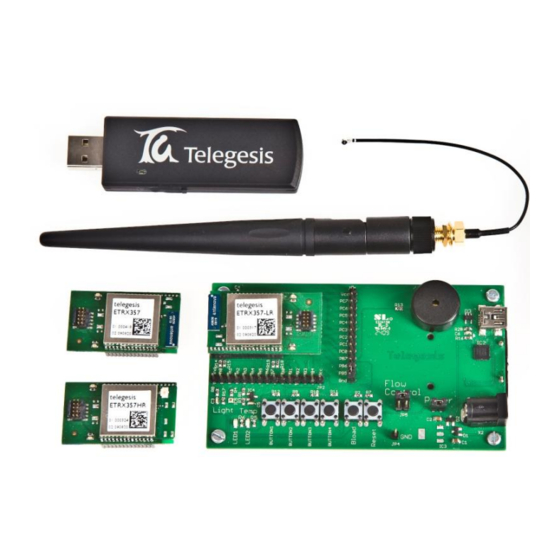
ETRX357 Development Kit 6.3 What’s in the ETRX357DVK box? 3 x ETRX357DV Development Boards 3 x USB cables 2 x ETRX357 on carrier boards 2 x ETRX357HR on carrier boards 2 x ETRX357-LRS on carrier boards 2 x ETRX357HR-LRS on carrier boards 1 x ETRX3USB USB stick 2 x ½-wave antennae 2 x ¼-wave antennae... -
Page 8: Setting Up The Hardware
ETRX357 Development Kit 7 Setting up the Hardware In the development kits are all four versions of the module. They can be powered from either a USB hub, the mains (via a suitable power supply) or batteries. Figure 3. ETRX357-LR Module on Carrierboard plugged on to Devboard 8 ETRX357 pinout The functions of each of the ETRX357 pins depend on the firmware. - Page 9 ETRX357 Development Kit Default Default alt fn direction Name Index Pad Main function Alternate function setting S17= S15= 0142CC 00000600 Enable TX_active on ETRX357 {4} ADC3 (light sensor) {2} ADC2, PWM {2} LED, Button 4, IRQ3 ADC1 {2} ADC0 (temp sensor) Enabled Enabled Button 3, IRQ2 {1}...
-
Page 10: The Development Board
ETRX357 Development Kit 9 The Development Board 9.1 Development Board Interface Description Figure 4. The development board Figure 4 shows the location of the connectors described below. Programming Connector: The 10-way programming connector X3 is used to program the ETRX357 module from a Silicon Labs InSight Adaptor. It is duplicated on the carrier board, and will not normally be fitted in the Development Board. - Page 11 ETRX357 Development Kit I/O breakout: JP1 and JP2 give access to the I/O on the ETRX357 module. The individual pins are labelled on the circuit board, and the pin numbering (PA0, PB1 etc) matches that of the EM357 chip inside the module.
-
Page 12: Development Board Sensors
ETRX357 Development Kit Power supply jumpers: links must be inserted at JP3 and JP6 according to the DC supply feed. JP3 can be left connected at all time, but it disconnects the serial interface lines and prevents power drain through them when the serial (USB) interface is not used. This will minimise the current drain from a battery and produce a more accurate reading of the current consumption. -
Page 13: The Carrier Board
ETRX357 Development Kit 10 The Carrier Board Figure 8. The carrier board The ETRX357 carrier board has two LEDs. Carrier board functionality LED1 LED2 Table 5. Carrier board LEDs Programming Connector: The 10-way programming connector X4 is used to program the ETRX357 module from a Silicon Labs InSight Adaptor. - Page 14 ETRX357 Development Kit Figure 9. File location After the files are installed you may have to restart the computer: Figure 10. Request to restart After you connect the devboard Windows® will prompt that new hardware has been found. If you have not run ‘TGvcpInstaller_xx.exe’...
- Page 15 ETRX357 Development Kit Figure 12. Satisfactory completion Please note that each devboard and USB stick has a unique serial number which requires the installation procedure to be repeated with every new unit being attached to the computer. This allows multiple devices to be used on the same computer at any one time. If a USB stick is unplugged and re-inserted the computer recognises it without having to repeat the installation process, and the USB device retains its former COM port number.
- Page 16 ETRX357 Development Kit Figure 13. Device Manager Once the correct COM port has been selected, the Telegesis Terminal software can be used to control the devboard as described in chapter 11. Figure 14. Telegesis Terminal ©2016 Silicon Labs - 16 - ETRX357DVK Product Manual (Rev 1.12)
-
Page 17: Application Software
ETRX357 Development Kit 12 Application Software The command line of the ETRX357 can be accessed using any terminal software program such as HyperTerminal®. Simply set up HyperTerminal® to connect to the appropriate COM port at 19200bps, Data bits - 8, Parity - none, Stop bits - 1, Flow Control – none (ETRX357 factory default). To speed up evaluation Telegesis provides its own Terminal Application Software program which allows enhanced functionality especially suited to the ETRX357 modules. -
Page 18: Software Set-Up
ETRX357 Development Kit 12.1 Software Set-up Telegesis Terminal R4.0 no longer needs .NET Framework Version 1.1 which was required for earlier versions. Download Telegesis Terminal from our website at www.silabs.com/telegesissoftware With recent operating systems such as Windows 7, it is advisable to right-click on the Telegesis Terminal setup program and select “Run as administrator”. -
Page 19: The Menu Bar
ETRX357 Development Kit To allow for easier identification, the EUI64 IDs in the device list can be named. When right clicking on any EUI64 ID a name can be associated with the respective ID - Figure 17. Figure 17. Device Naming The menu bar Figure 18. -
Page 20: A Quick Start
ETRX357 Development Kit XMODEM is generally used when bootloading a new firmware file on to a module. 12.3 A Quick Start This section gives you a quick introduction on how to get started. Power up the node connected to the PC and open a connection to the correct device; refresh the list of COM ports if the expected device is not shown. -
Page 21: Mesh Networking
ETRX357 Development Kit case of the two MCBs provided with the previous ETRX2-based DVKA) you will just need to wait for them to join the network automatically. By default, once every minute all nodes (except coordinators) are set up to check whether there are any neighbours on the same PAN nearby, or if they have been orphaned. -
Page 22: Configuring Buttons For Your Setup
ETRX357 Development Kit 12.4 Configuring Buttons for your Setup You can open several copies of Telegesis Terminal on the same PC, so if you have two or more development boards connected to a PC try sending messages between them using the Broadcast or Unicast buttons. -
Page 23: Using Leds And Adcs On The Etrx357
ETRX357 Development Kit 12.5 Using LEDs and ADCs on the ETRX357 The LEDs are connected to the ETRX357 in a pull-down arrangement so each output must be set to ‘0’ to turn on its LED. Refer to Table 3 for details of the various connections; since they are distributed across the 16 I/O pins some examples of typical functions are given here for convenience. -
Page 24: Temperature Display
ETRX357 Development Kit 12.6 Temperature display The AT command set provides two powerful features: 1. A node can be defined as a “sink”. It broadcasts its address to the rest of the network, so the other devices can use commands and built-in functions that send data to the sink. In this way, an application can be designed without the need to know in advance the address of the sink node, which will be different in each installation. -
Page 25: Firmware Upgrades
ETRX357 Development Kit 13 Firmware upgrades If required, the firmware of the ETRX357 modules can be upgraded serially as well as over the air. Over-the-air upgrading is primarily a function of the Silicon Labs bootloader and it is not available with the early bootloader versions. - Page 26 ETRX357 Development Kit Figure 22. File Transfer Window When the transfer has been completed successfully, press Enter again in order to return to the bootloader menu (shown in Figure 21) and option ‘2‘ to run the downloaded application software. If the application software has a baudrate other than 115200bps, this will need to be changed to the application baudrate as described above –...
-
Page 27: Over The Air Firmware Upgrades
ETRX357 Development Kit 13.2 Over the Air Firmware Upgrades ETRX2 and ETRX357 features With the ETRX2, upgrading over the air is possible by cloning a local node’s firmware to a remote node, so if new firmware has to be introduced to the network it can be downloaded serially to a master node, which then can clone itself to one node after the other in turn given the target node is only a single hop away. -
Page 28: Recovering On The Default Channel
ETRX357 Development Kit Figure 23. Passthrough bootloading Recovering on the default channel If the target device is reset or power cycled whilst in the bootloader, the unit will listen for new firmware files on channel 13. It is therefore required to set up a node on channel 13 and repeat the recovery action described in the previous section. -
Page 29: Hardware Enhancement Kit
ETRX357 Development Kit 14 Hardware enhancement kit For users who are developing their own firmware on the Silicon Labs EM3587 chip, Telegesis offer an enhancement pack for the ETRX357 Development Kit or the Silicon Labs EM35x Development Kit that contains EM3587-based modules on carrier boards. This will enable you to download your application to the modules and verify its operation on our development kit boards. -
Page 30: Devboard Schematic
ETRX357 Development Kit 15 Devboard Schematic ©2016 Silicon Labs - 30 - ETRX357DVK Product Manual (Rev 1.12) - Page 31 ETRX357 Development Kit ©2016 Silicon Labs - 31 - ETRX357DVK Product Manual (Rev 1.12)
-
Page 32: Carrier Board Schematic
ETRX357 Development Kit 16 Carrier Board Schematic ©2016 Silicon Labs - 32 - ETRX357DVK Product Manual (Rev 1.12) -
Page 33: Etrx357 Ordering Information
ETRX357 Development Kit 17 ETRX357 Ordering Information Ordering/Product Code Description Telegesis Wireless Mesh Networking Module with Silicon Labs ETRX357 ZigBee® Technology: Telegesis AT Style Command Interpreter based on Silicon Labs’ EmberZNet stack Integrated 2.4GHz Antenna Telegesis Wireless Mesh Networking Module with Silicon Labs ETRX357HR ZigBee®... - Page 34 The products are not designed or authorized to be used within any Life Support System without the specific written consent of Silicon Laboratories. A "Life Support System" is any product or system intended to support or sustain life and/or health, which, if it fails, can be reasonably expected to result in significant personal injury or death.
Need help?
Do you have a question about the Telegesis ETRX357DVK and is the answer not in the manual?
Questions and answers