
Related Manuals for Crestron VX Series


Summary of Contents for Crestron VX Series
- Page 1 IV-SAM-VXN-1B, IV-SAM-VXP-1B, and IV-SAM-VXS-1B 1 Beyond Automate™ VX Series Product Manual Crestron Electronics, Inc.
- Page 2 United States and/or other countries. Other trademarks, registered trademarks, and trade names may be used in this document to refer to either the entities claiming the marks and names or their products. Crestron disclaims any proprietary interest in the marks and names of others. Crestron is not responsible for errors in typography or photography.
-
Page 3: Table Of Contents
Contents Overview Features IV-SAM-VXP-1B Features IV-SAM-VXS-1B Features IV-SAM-VXN-1B Features IV-PROSERVICE-1B Features Physical Description Specifications IV-SAM-VXP-1B Specifications Product Specifications IV-SAM-VXS-1B Specifications Product Specifications IV-SAM-VXN-1B Specifications Product Specifications Installation In the Box Wire the Camera System Connect to the System Configuration Initial Setup Assign Network Interfaces Set Static IP Addresses Use Remote Support... - Page 4 Create Layouts Configure Audio Operation Basic Operation Main Menu Layouts Menu Room Configs Menu Cameras Menu Scenarios Menu Camera Setup Tool Resources Crestron Support and Training Product Certificates Related Documentation iv • Contents Product Manual — Doc. 9324C...
- Page 5 v • Contents Product Manual — Doc. 9324C...
-
Page 6: Overview
Overview The 1 Beyond Automate™ VX series provides voice-activated camera switching solutions that bring a full multicamera studio experience to meetings, town halls, and classrooms. Camera switching and movement are done automatically based on the active speaking participant. Automate VX comes with built-in recording and streaming capability along with outputs for video conferencing. -
Page 7: Features
Features Refer to the following sections for more information on the 1 Beyond Automate™ VX model features. IV-SAM-VXP-1B Features on page 3 IV-SAM-VXS-1B Features on page 5 IV-SAM-VXN-1B Features on page 7 IV-PROSERVICE-1B Features on page 9 2 • IV-SAM-VXN-1B, IV-SAM-VXP-1B, and IV-SAM-VXS-1B Product Manual —... -
Page 8: Iv-Sam-Vxp-1B Features
1 Beyond Camera Systems Remote Professional Services. An Equipment Proposal issued by the Crestron Sales Support Services team is required before placing an order for the IV-SAM-VXP-1B Automate™ VX Pro. All orders must reference the Equipment Proposal number and include the complete camera system outlined in the Equipment Proposal, including Professional Services. - Page 9 Browser or Third-Party Control Enable auto-switching, record/stream, and change room configurations or layouts using a Crestron® control module. An adaptable API is available for customizable user-interfaces on third-party control systems. Conference, Stream, and/or Record In addition to high-quality output for hard or soft codecs, the system has a built-in encoder and recorder to enable multiple live streams and over 100 hours of recording.
-
Page 10: Iv-Sam-Vxs-1B Features
1 Beyond Camera Systems Remote Professional Services. An Equipment Proposal issued by the Crestron Sales Support Services team is required before placing an order for the IV-SAM-VXS-1B Automate™ VX . All orders must reference the Equipment Proposal number and include the complete camera system outlined in the Equipment Proposal, including Professional Services. - Page 11 Browser or Third-Party Control Enable auto-switching, record/stream, and change room configurations or layouts using a Crestron® control module. An adaptable API is available for customizable user-interfaces on third-party control systems. Conference, Stream, and/or Record In addition to high-quality output for hard or soft codecs, the system has a built-in encoder and recorder to enable multiple live streams and over 100 hours of recording.
-
Page 12: Iv-Sam-Vxn-1B Features
1 Beyond Camera Systems Remote Professional Services. An Equipment Proposal issued by the Crestron Sales Support Services team is required before placing an order for the IV-SAM-VXN-1B Automate™ VX . All orders must reference the Equipment Proposal number and include the complete camera system outlined in the Equipment Proposal, including Professional Services. - Page 13 RESTful API for Crestron® and Third-Party Control Enable auto-switching, record/stream, and change room configurations or layouts using a Crestron® control module. An adaptable API is available for customizable user-interfaces on third-party control systems. Conference, Stream, and/or Record In addition to high-quality output for hard or soft codecs, the system has a built-in encoder and recorder to enable multiple live streams and over 100 hours of recording.
-
Page 14: Iv-Proservice-1B Features
1 Beyond Camera Systems Remote Professional Services provides support for commissioning your Automate™ VX voice-activated camera tracking solution. An Equipment Proposal issued by Crestron’s Sales Support Services team is required before placing an order for any Automate VX system. All orders must reference the Equipment Proposal number and include the complete camera system as set forth in the Equipment Proposal, including 1 Beyond Camera Systems Remote Professional Services (IV-PROSERVICE-1B). - Page 15 Remote Commissioning and Validation Following installation, the Crestron support team will connect remotely with your onsite team to help deploy the solution and configure the Automate VX software. The support team accesses the Automate VX system remotely with your permission and assistance.
-
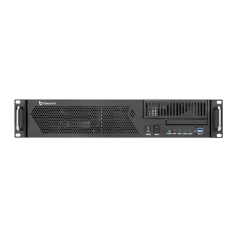
Page 16: Physical Description
Physical Description The camera switching device provides the following connectors and indicators. IV-SAM-VXP-1B Connectors and Indicators IV-SAM-VXN-1B Connectors and Indicators IV-SAM-VXS-1B Connectors and Indicators Name Description Power AC power BIOS Flashback Button Not used Wi-Fi Connects the antenna to the onboard Wi-Fi™ network chip HDMI Not used USB 3.2 Gen 1 2x USB Type-A ports for peripheral device connections... - Page 17 Name Description Audio Connections Orange: Central/bass speaker out Blue: Line in Black: Rear speaker out Green: Headphone/speaker out Pink: Microphone in Optical: Optical SPDIF out NIC 1 1 Gbps RJ-45 Ethernet port USB 3.2 Gen1 USB Type-A port for peripheral device connections USB 3.2 Gen2 USB Type-C® port for faster data rates Thunderbolt™...
-
Page 18: Specifications
Specifications Refer to the following sections for more information on the specifications for various 1 Beyond Automate™ VX models. IV-SAM-VXP-1B Specifications on page 14 IV-SAM-VXS-1B Specifications on page 16 IV-SAM-VXN-1B Specifications on page 18 Product Manual — Doc. 9324C IV-SAM-VXN-1B, IV-SAM-VXP-1B, and IV-SAM-VXS-1B • 13... -
Page 19: Iv-Sam-Vxp-1B Specifications
IV-SAM-VXP-1B Specifications Product specifications for the IV-SAM-VXP-1B are provided below. Product Specifications Automate VX Pro Capabilities Titles, Graphics, Layouts Titles, logos, backgrounds can be added, Easy-to-use graphic designer to create any multi-source layout Program Record MP4 file (H.264 codec). User-selectable bitrate up to 10 Mbps Recording Capacity Records to internal 1TB SSD storage Streaming Encoder... - Page 20 Dimensions Height 3.5 in. (89 mm) Width 16.75 in. (425 mm) Depth 14.5 in. (368 mm) Weight 14 lb (6.35 kg) Product Manual — Doc. 9324C IV-SAM-VXN-1B, IV-SAM-VXP-1B, and IV-SAM-VXS-1B • 15...
-
Page 21: Iv-Sam-Vxs-1B Specifications
IV-SAM-VXS-1B Specifications Product specifications for the IV-SAM-VXS-1B are provided below. Product Specifications Automate VX Capabilities Titles, Graphics, Layouts Titles, logos, backgrounds can be added, Easy-to-use graphic designer to create any multi-source layout Program Record MP4 file (H.264 codec). User-selectable bitrate up to 10 Mbps Recording Capacity Records to internal 500GB SSD storage Streaming Encoder... - Page 22 Dimensions Height 3.5 in. (89 mm) Width 16.75 in. (425 mm) Depth 14.5 in. (368 mm) Weight 14 lb (6.35 kg) Product Manual — Doc. 9324C IV-SAM-VXN-1B, IV-SAM-VXP-1B, and IV-SAM-VXS-1B • 17...
-
Page 23: Iv-Sam-Vxn-1B Specifications
IV-SAM-VXN-1B Specifications Product specifications for the IV-SAM-VXN-1B are provided below. Product Specifications Automate VX Plus Capabilities Titles, Graphics, Layouts Titles, logos, backgrounds can be added, Easy-to-use graphic designer to create any multi-source layout Program Record MP4 file (H.264 codec). User-selectable bitrate up to 10 Mbps Recording Capacity Records to internal 500GB SSD storage Streaming Encoder... - Page 24 Dimensions Height 3.5 in. (89 mm) Width 16.75 in. (425 mm) Depth 14.5 in. (368 mm) Weight 14 lb (6.35 kg) 19 • IV-SAM-VXN-1B, IV-SAM-VXP-1B, and IV-SAM-VXS-1B Product Manual — Doc. 9324C...
-
Page 25: Installation
Installation Use the following procedures to install the Automate VX system. In the Box Qty. Description IV-SAM-VXP-1B, IV-SAM-VXS-1B, or IV-SAM-VXN-1B Automate™ VX Camera Switcher Additional Items Rail, 20 in. (508 mm) Power Cord, IEC Wi-Fi™ Network Antenna SDI to HDMI® Signal Converter Feet Set, Chassis IV-SAM-VXS-1B and IV-SAM-VXP-1B Only Mini DisplayPort™... -
Page 26: Connect To The System
3. Connect each PTZ camera to the SDI® ports of the Automate VX device using HD-SDI cables. Ensure the numbered SDI port corresponds to the camera number determined in step 1. NOTE: Each PTZ camera should be connected to a network switch via Ethernet and can be powered via PoE+ (Power over Ethernet Plus) with 30 W power. - Page 27 3. Connect to the camera switching device in the remote desktop client using the following IP address: 10.1.10.2. Remote Desktop Client Login 4. When prompted, enter the following default login credentials: Username: Valued Customer Password: 1beyond NOTE: This Username and Password above are the Windows system login credentials too. Product Manual —...
-
Page 28: Configuration
Configuration Use the following procedures to configure the Automate VX system. This section provides the following information: Initial Setup on page 24 Room Designer on page 26 System Configuration on page 68 Wirecast Configuration on page 87 23 • IV-SAM-VXN-1B, IV-SAM-VXP-1B, and IV-SAM-VXS-1B Product Manual —... -
Page 29: Initial Setup
Initial Setup Use the following procedures to set up the Automate VX system following installation. Assign Network Interfaces The Automate VX system has two NICs labeled Ethernet and Ethernet 2. The Ethernet ports have the following default addressing configuration: The NIC 1 port is set as a static IP (10.1.10.2) for initial configuration via the Windows® Remote Desktop application. -
Page 30: Use Remote Support
Assigning IP addresses for 1 Beyond cameras must be done through the 1 Beyond Camera Manager. For more information regarding assigning IP addresses for 1 Beyond cameras, refer to the documentation for your 1 Beyond camera model. It is also recommended to change the camera names to match the global camera IDs that have been designated in the Automate VX system software. -
Page 31: Room Designer
Room Designer The Automate VX system contains the Room Designer tool that uses the scaled floor plan (in the form of an image) to create a framework for how the Automate VX system operates. The Automate VX system relies on audio gating or positional information provided by 3 party devices in order to determine where an active speaking participant is located in a room. - Page 32 NOTE: The login credentials are for the admin user. For any other users, use the username and password of the other user to login. For more information, refer to Add User on page The web configuration interface is displayed with the Main tab open by default. To access Room Designer from the Main tab, select the pencil icon in the top right of the menus.
- Page 33 The Room Designer page will be displayed. Room Designer Default Page Product Manual — Doc. 9324C IV-SAM-VXN-1B, IV-SAM-VXP-1B, and IV-SAM-VXS-1B • 28...
- Page 34 Room Designer by default comes with a demo layout tied to Configuration 1. This is only a template and should not be used as an actual room layout. To upload a floor plan for a room design, select the Choose File button under the Floor Plan Upload banner. This will open a file explorer window.
- Page 35 Alternately, if a project has been already created and needs to be imported into the system, select the Choose File button under the Upload Project banner. This will open a file explorer window. Navigate to the desired room designer project and select it (this will be a .1brd file). The project will be imported in its entirety with all of the formatting previously created.
-
Page 36: Configuring A Room Designer Project
Configuring a Room Designer Project The following settings are available in Room Designer. General Settings Select the Settings tab on the left hand side of the room designer page to access the following general room designer settings. Settings Tab 31 • IV-SAM-VXN-1B, IV-SAM-VXP-1B, and IV-SAM-VXS-1B Product Manual —... - Page 37 Set Origin: Selecting Set Origin will create a red circle that has a coordinate next to it (x,y). This is the reference point that is used for all of the coordinates used inside of room designer (camera, microphone, and virtual microphone locations). By default, the origin point will appear in the top left of the room layout at the coordinate 0,0.
- Page 38 Set Scale: Setting the scale for the room will provide the Automate VX system a reference to the room size. Selecting Set Scale will make the mouse cursor act as the beginning point of a measurement line. Navigate the mouse cursor to a point in the room where the length or width of the object (for example, a conference table) is known.
- Page 39 Measurement Dialog Box NOTE: Ensure that this process is done accurately and precisely. If the reference object was not measured correctly, then the performance of the Automate VX system may suffer. Add Camera Device: Selecting Add Camera Device will add a pentagon shaped object into the room layout that designates a camera within the room.
- Page 40 Add Microphone Device: Selecting Add Microphone Device will add a square shaped object into the room layout that designates a microphone device within the room. Place a Microphone Device in each location where there is a microphone within the room layout. For more information, refer to Configuring Microphone Devices on page 49 When using a DSP such as Biamp Tesira, QSC Q-Sys Core, or Shure IntelliMix Room as a...
- Page 41 Add Default Shot: A Default Shot is what the configuration will change the camera shot to after a specified period of silence in the room. For information on how to change the period of silence for a Default Shot to occur, refer to AutoSwitch Settings on page Selecting Add Default Shot will add a circle shaped object into the room layout that designates the default camera shot for the configuration.
- Page 42 Shift Grid: Selecting Shift Grid allows for the grid overlay created by the Set Scale feature to be moved. Once selected, the room layout will turn red. Click the grid and move it to the desired location. Shift Grid Overlay NOTE: Shifting the grid will not affect the scaling, it will remain as a 2ft by 2ft (60mm by 60mm) grid regardless of the grid's placement.
- Page 43 NOTE: To remove a Microphone Device further down in the order (such as microphone 2 of 4), all preceding cameras must be first removed. As a workaround, copy the information for the last Microphone Device in the order (in this example, microphone 4) into the settings for the Microphone Device that should be deleted (camera 2).
- Page 44 Shot Visualization: Enabling this option will show which Camera Devices are aimed at a particular Virtual Mic position (or Default Shot). A cone will go from the Camera Device to the Virtual Mic position, and the size of the cone will coincide with the Shot Width. For more information on configuring Virtual Mics with Camera Devices, refer to Configuring Virtual Mics and Blocking Zones on page 56...
- Page 45 Live Mode: Enabling this option will display a grid view in Wirecast to show all live Camera Device feeds at once. When a virtual mic is selected with Live Mode enabled, the Primary and Secondary Camera Devices will point at the location of the Virtual Mic in the room automatically.
- Page 46 Show Global Mic #: By default, Room Designer numbers the Virtual Mics and Blocking Zones in the system separately based on their connected Microphone Device. Global Mic # OFF When Show Global Mic # is turned on, the total number of virtual mics and blocking zones are shown instead.
- Page 47 Show Mic Coverage: Enabling this option will show the circular range of Virtual Mic positions. This range indicates the area that the Microphone Device will switch the camera feed to the Virtual Mic's location when audio is detected. NOTE: The Mic Coverage feature is only applicable to the Shure MXA920 XYZ, Sennheiser TCC2, and Yamaha ADECIA™ microphones.
- Page 48 Adjudicator Settings Select the Adjudicator tab on the left hand side of the room designer page to access the following room adjudicator settings. Adjudicator Tab To enable the adjudicator, turn on the Enabled toggle. This should be enabled when there is a DSP involved with the room configuration.
-
Page 49: Configuring Camera Devices
Notes Page Select the Notes tab on the left hand side of the room designer page to access the notes page. Information or any notes about the current room configuration can be placed here, and will be saved for future use. Configuring Camera Devices Camera Devices are the camera outputs that the Automate VX system uses to display the camera feed. - Page 50 The following Camera Device settings are available: Model: Select the drop-down menu under the Model title to select the camera model for the respective Camera Device. This should match the same model that was used in the physical room. The following camera models are available: Camera Model Menu general: Select this model when the camera model being used is not a PTZ-12.
- Page 51 Network: Enter the IP address of the camera that is being used as the Camera Device in the IP text field. 1 Beyond cameras IP addresses can be obtained and changed in the 1 Beyond Camera Manager. For more information about the 1 Beyond Camera Manager, refer to the 1 Beyond Camera Manager Product Manual.
- Page 52 Position: The X, Y, and Z fields are the locations of the Camera Device in the room layout. These coordinates can be entered manually into their respective fields, or the Camera Device can just dragged and placed into the correct location. The units used in the text fields are either in inches or millimeters depending on the unit is selected in the View tab.
- Page 53 Orientation: The Pan, Tilt, and Roll fields are the direction the Camera Device's lens is when it is in their default (resting) state. The direction that the camera lens is facing is indicated by the blue box with LENS on it. The LENS is the bird-eye view of the top of the camera, and the orientation of the blue box should match the way the camera is setup in the physical room.
-
Page 54: Configuring Microphone Devices
Configuring Microphone Devices Microphone Devices are the microphones in a room that the Automate VX system uses to receive audio from active speaking participants. Microphone Devices are indicated in Room Designer as square shaped nodes. For more information about adding Microphone Devices to a room layout, refer to View Settings on page 38 There are three different types of microphones, and the way that they are handled in Room... - Page 55 Model: Select the drop-down menu under the Model title to select the microphone model for the respective Microphone Device. This should match the same model that was used in the physical room. The follow microphone models are available: Microphone Device Model Menu Biamp Tesira generic QSC Q-SYS™...
- Page 56 Shure MXA910 Shure MXA920 XYZ (beta) Shure MXA920-Lobe Shure MXCW Shure P300 TAIDEN® Conference System Yamaha ADECIA NOTE: If the microphone that is being used in the room is not one of the models listed above, then select generic. Generic microphones may not operate properly with the Automate VX system.
- Page 57 IP Enter the IP address of the microphone in the IP text field. Microphone Device Network Setting Product Manual — Doc. 9324C IV-SAM-VXN-1B, IV-SAM-VXP-1B, and IV-SAM-VXS-1B • 52...
- Page 58 Position: The X, Y, and Z fields are the locations of the Microphone Device in the room layout. These coordinates can be entered manually into their respective fields, or the Microphone Device can just dragged and placed into the correct location. The units used in the text fields are either in inches or millimeters depending on the unit is selected in the View tab.
- Page 59 Orientation: The Pan field is the direction that the microphone is facing. The Microphone Device should be placed in the room layout with the handle extending out of the Microphone Device in the same direction that manufacturer's logo is in the physical room. Change the value in the Pan field to match the Microphone Device to the physical microphone, or simply use the handle to spin the Microphone Device.
- Page 60 Microphone Device Handle Mics: Refer to Configuring Virtual Mics and Blocking Zones on page Adjudicator: Refer to Configuring Adjudicators on page 66 55 • IV-SAM-VXN-1B, IV-SAM-VXP-1B, and IV-SAM-VXS-1B Product Manual — Doc. 9324C...
- Page 61 Duplicate Device: Click the Duplicate Device button to create a copy of the currently selected Microphone Device. Once the button is clicked, click again in the desired location for the copied Microphone Device. This also duplicates all Virtual Mic positions, Blocking Zone positions, and Adjudicator settings as well.
- Page 62 Microphone Device Settings Navigate to the Mics section of the Microphone Device Settings menu. Microphone Device Settings: Mics 57 • IV-SAM-VXN-1B, IV-SAM-VXP-1B, and IV-SAM-VXS-1B Product Manual — Doc. 9324C...
- Page 63 The following Virtual Mic settings are available: Add Virtual Mic: Select this option to add a Virtual Mic to the room layout. The Virtual Mic will be placed directly on top of the Microphone Device. Click and drag the Virtual Mic to the position where a talker would be in the room layout.
- Page 64 Add Blocking Zone: Select this option to create a Blocking Zone into the room layout. A Blocking Zone is an area that the Microphone Device will ignore audio from. This is particularly useful when there is an ambient sound in the room (vents, AC unit, etc.). Blocking Zones should also be used to define the border between multiple intelligent microphones by placing blocking zones just beyond the furthest Virtual Mics from each Microphone Device.
- Page 65 Virtual Mic Settings Once a Virtual Mic is placed in the correct location, click on the Virtual Mic to open the Virtual Mic Settings. The menu will appear on the right side of the screen. Virtual Mic Settings The following Virtual Mic settings are available in this menu: Product Manual —...
- Page 66 Remove Virtual Mic: Select this option to delete the currently selected Virtual Mic. Position: The X:, Y:, and Z: fields are the locations of the Virtual Mic in the room layout. These coordinates can be entered manually into their respective fields, or the Virtual Mic can just dragged and placed into the correct location.
- Page 67 Cameras: There are two separate drop-menus under the Cameras title, one for Primary and one for Secondary. These drop-down menus are for cameras that will be showing the Virtual Mic position through the camera feed. Select the desired camera that will be broadcasting the Virtual Mic location in the Primary drop-down menu, and select a back- up camera for the Virtual Mic in the Secondary drop-down menu.
- Page 68 Shot Width: Use the slider or input a value into the text field to change the size of the camera shot. Enable Shot Visualization in the View tab to see the size of the camera shot in the room layout. Enable Live Mode in the View tab to see how the Shot Width affects the camera shot in real-time on Wirecast.
- Page 69 SuperLobe: A SuperLobe is a way to group a section of Virtual Mic positions together, so that when one of the Virtual Mic positions pings audio to the Microphone Device, the Camera Device will set the camera shot on the SuperLobe position rather than the specific Virtual Mic position.
- Page 70 Chairman Mic: Enable this option to make the currently selected Virtual Mic a chairman. This means that whenever audio is picked up from this Virtual Mic location, it will take priority over the other Virtual Mic positions. The camera shot switch to that Virtual Mic position regardless of audio signals from other Virtual Mic positions.
- Page 71 PTZ Control: PTZ controls adjust how a camera will display the Virtual Mic position. For the best results, enable Live Mode in the View tab to see how these settings change the camera shot in Wirecast. Virtual Mic PTZ Controls The toggle switch is by default set to whichever camera is selected as the Primary (in the pictured example, 3 is the Primary camera).
- Page 72 Once a DSP is configured to be an adjudicator, select a Microphone Device to make the Microphone Device settings appear on the right side of the screen. Locate the Adjudicator setting in the Microphone Device settings menu. Adjudicator Setting In the Channel text field, input the desired channel that will be used for communication between the microphone and the adjudicator.
-
Page 73: System Configuration
NOTE: Most system configuration can be accomplished by using the Intelligent Video Room Designer tool. This tool is available on the Crestron website and locally on the Automate VX system. For more information on using the tool, refer to Room Designer on page 26 Access the Web Configuration Interface To access the web configuration interface for the Automate VX system, open the Chrome®... - Page 74 NOTE: The login credentials are for the admin user. For any other users, use the username and password of the other user to login. For more information, refer to Add User on page The web configuration interface is displayed with the Main tab open by default. NOTE: The Main tab is also where the operation of the Automate VX system occurs.
- Page 75 To access the system settings: 1. Select the pencil icon on the top right of the page to open Room Designer. Main Tab to Room Designer Product Manual — Doc. 9324C IV-SAM-VXN-1B, IV-SAM-VXP-1B, and IV-SAM-VXS-1B • 70...
-
Page 76: General Settings
2. Select the gear icon at the top right of the page to open the system settings. Room Designer Page When trying to access the system settings anywhere else besides the Main tab, the gear icon is present. General Settings Select the General tab to view the available general system settings. - Page 77 Output Settings The following settings are used to turn the available camera outputs on and off, and to select the desired resolution for each output. Output Settings Three output settings are provided that can be turned on or off: SDI, NDI, and Virtual Camera. Each output has a drop-down menu with the following resolution output options: NTSC 1080i 50...
- Page 78 Layout Settings Each layout is given an ID (A to Z) and can be named by selecting the appropriate Layout Name text field. To add additional layouts, select Add Layout. A new layout is added with the next available letter ID. To remove layouts, select Remove Layout. The last available layout is removed (for example, if Layouts A-D are configured, Layout D will be removed).
- Page 79 Select the Enabling Pause check box to provide pausing functionality during recording. Pausing will create incomplete recordings which are stored in D:/Recording_Temp. Once a recording has been stopped, the incomplete recordings are joined into a complete recording and saved in D:/Recordings.
- Page 80 NOTE: The Automate VX system reboots daily to better the performance of the system. The system will perform the action selected for Startup Action upon reinitialization. Push-to-Talk Settings The following push-to-talk settings are provided. Push-to-Talk Settings Select the Enable Side by Side check box to turn on side-by-side shots. A side-by-side shot is a split screen shot that captures two active participants who are speaking mostly at the same time.
-
Page 81: Titling Settings
AutoSwitch Settings The following AutoSwitch settings are provided. Auto Switch Settings Noise Delay: Determines how long a noise needs to occur before the system recognizes it. This feature helps to avoid switching based on coughs or other short sounds. Pause Delay: Determines how long after an active participant stops speaking before the camera will switch to another camera or a default shot. - Page 82 Microphone Table The Microphone Table shows the relationship between microphone devices and virtual microphones in the system. The Device Number column indicates the microphone device, and the Mic Number column shows the virtual microphone associated with the microphone device. Microphone Table Microphone Devices are configured through Room Designer.
- Page 83 Selecting the check box next to the Enable Titling setting will allow one of the following three selections to be available: Select Static Titling from Settings to add a third column to the Microphone Table for entering titles manually. Microphone Table - Static Title Column Select Dynamic Titling from Mic.
-
Page 84: Scenario Settings
Scenario Settings Select the Scenarios tab to view the available scenario settings. The Scenario Settings shows the currently available scenarios for the system. Scenario Settings To add additional scenarios, select Add Scenario. A new scenario will be added with the next available numbered ID. -
Page 85: Advanced Settings
Advanced Settings Select the Advanced tab to view the available advanced settings. Advanced Tab The following advanced settings can be configured. Room Configurations The Room Configurations setting allows for different microphones and room furniture arrangements to be used. This is especially helpful within divisible and multipurpose rooms. Each room configuration saves a separate copy of all the settings in the Automate VX system. - Page 86 Selecting a room configuration can also be called with an API or Crestron command. For more information on using the Automate VX API, refer to the appropriate documentation at https://developer.crestron.com. Load Microphone Device Preset When using multiple room configurations, it is possible to load corresponding presets for Shure Intellimix Devices such as MXA910, MXA310, P300, and Intellimix Room.
- Page 87 By default, all recordings are saved to local storage of the Automate VX system at D:\Recordings\VX. The Copy Files button on the home page copies these files to the specified destination when selected. For more information, refer to Basic Operation on page The Destination path can be set to a mapped network location, a full network address, or an external drive.
-
Page 88: Admin And User Settings
Admin and User Settings Admin and User settings are accessible by selecting the Users icon at the top right of the page while logged in as an admin. Users Icon The admin user has full access to all settings. New users can be created with full or limited access to system settings. - Page 89 Permissions Select the Permissions tab to set permissions for additional users in the system. For example, an end user could be given permissions only to operate the AutoSwitch feature. Additional users will need to be created using the Add User settings to change permissions for other users. For more information, refer to Add User on page User Settings - Permissions...
- Page 90 Add User The following settings to add a user are provided. User Settings - Add User Select the Add User tab to add a new user. Enter the new username and password in the appropriate text fields, then select Add User. Change Password Select the Change Password tab to update the password for an existing user.
- Page 91 Delete User The following settings to delete a user are provided. User Settings - Delete User Select the Delete User tab to delete an existing user. Enter the username of the user to delete, then select Delete User. Product Manual — Doc. 9324C IV-SAM-VXN-1B, IV-SAM-VXP-1B, and IV-SAM-VXS-1B •...
-
Page 92: Wirecast Configuration
Wirecast Configuration The Automate VX system uses Wirecast® streaming software to change live shots, layouts, and output. During initial setup, changes may need to be made to the Wirecast document to customize the system, such as setting custom layouts with logos. The Wirecast document is located within C:\Program Files\1 Beyond\Automate Project.wcst. -
Page 93: Create Layouts
Side-by-Side Wirecast Shots When creating side-by-side shots in the Wirecast document, place the first camera on the left and the second camera on the right. Add Titles Titles are placed in shots in the layer above the basic and side-by-side shots. Each layout has a regular title and a side-by-side title (for example, A_Title and A_Title_S). -
Page 94: Configure Audio
Configure Audio Audio input to the Automate VX system is not required for voice-activated camera switching. For video conferencing, send audio directly from your DSP to your codec with a 400ms delay in order to ensure proper lip sync. For local recording or streaming with the system, activate the installed Dante Virtual Soundcard by purchasing a license from www.audinate.com. -
Page 95: Operation
Operation Use the following procedures to operate the Automate VX system. This section provides the following information: Basic Operation on page 91 Camera Setup Tool on page 97 Product Manual — Doc. 9324C IV-SAM-VXN-1B, IV-SAM-VXP-1B, and IV-SAM-VXS-1B • 90... -
Page 96: Basic Operation
Basic Operation The following procedures describe how to operate basic functions of the Automate VX system. For information on how to enter the web user interface, refer to Access the Web Configuration Interface on page When the web user interface is opened, there are five main tabs that control the operation of the Automate VX system. - Page 97 A green outline is shown around the button when AutoSwitching is turned on, and the system output will switch automatically based on the active speaking participant. Select AutoSwitch again to stop automated switching. NOTE: Automate VX may display an error when AutoSwitch is started. The error message will display the IP Address of any Microphone Devices or Camera Devices that it is unable to connect to.
-
Page 98: Layouts Menu
Layouts Menu Select the Layouts tab to view and select preset layouts for the Automate VX system. Layouts Menu Selections To change layouts during AutoSwitch mode, select the button that corresponds with the desired layout. The layout changes immediately, and the currently active layout is highlighted in green. The layouts are only used when AutoSwitch mode is enabled. -
Page 99: Room Configs Menu
Room Configs Menu Select the Room Configs tab to view and select preset room configurations for the Automate VX system. Room Configs Menu Selections To change room configurations, select the button that corresponds with the desired room configuration. The room configuration changes immediately. For more information about room configurations, refer to Room Configurations on page Product Manual —... -
Page 100: Cameras Menu
Cameras Menu Select the Cameras tab to view and select individual cameras for manual control. Cameras Menu Selections To select a camera for manual control, select a button under Cameras that corresponds to the desired camera. The live shot will change to the selected camera immediately. Use the PTZ Control settings to manually change the direction and zoom of the selected camera. -
Page 101: Scenarios Menu
Scenarios Menu Select the Scenarios tab to view and select available scenarios to choose from. Scenarios Menu Selections To change the current output to a scenario, select one of the created scenarios from the Scenarios list. This will make the current camera feed switch to the desired scenario. For more information about scenarios, refer to Scenario Settings on page Select the Wake button to turn the system on from sleep mode. -
Page 102: Camera Setup Tool
Camera Setup Tool The Automate VX system provides a Camera Setup tool that allows microphones to be paired with a corresponding camera shot for each scenario. Scenarios are predefined camera shots that can be utilized in various situations when intelligent speaker tracking is not desired. Scenarios can also be used to define the sleep and wake actions of the Automate VX system, for more information refer to Sleep and Wake Settings on page... - Page 103 To access the camera setup tool, select the camera icon within the settings page. Camera Icon Selection The Camera Setup page is displayed. Use the drop-down menu at the top of the page to change the room configuration. Then, use the drop-down menu under Camera Setup to select a virtual microphone position or a scenario.
- Page 104 The Scenario Setup page is displayed. The following controls are provided. Use these controls to configure any cameras that are to be used in this scenario. Select a numbered button next to the camera icon to select the cameras for the scenario. To add the cameras to the scenario, select Add to scenario when the numbered icon corresponding to the camera is highlighted green.
- Page 105 NOTE: If a noncamera shot is desired for a scenario (for example, using an image rather than a camera feed), use the Shot Layer in Wirecast to configure the camera feed for the scenario. Product Manual — Doc. 9324C IV-SAM-VXN-1B, IV-SAM-VXP-1B, and IV-SAM-VXS-1B • 100...
-
Page 106: Resources
Resources The following resources are provided for the Automate VX system. NOTE: You may need to provide your Crestron.com web account credentials when prompted to access some of the following resources. Crestron Support and Training Crestron True Blue Support Crestron Resource Library Crestron Online Help (OLH) support.crestron.com/app/answers/detail/a_id/1001561... - Page 107 This page is intentionally left blank. Product Manual — Doc. 9324C IV-SAM-VXN-1B, IV-SAM-VXP-1B, and IV-SAM-VXS-1B • 102...
- Page 108 Crestron Electronics, Inc. Product Manual — Doc. 9324C 15 Volvo Drive, Rockleigh, NJ 07647 12/20/22 Tel: 888.CRESTRON Specifications subject to Fax: 201.767.7656 change without notice. www.crestron.com...
Need help?
Do you have a question about the VX Series and is the answer not in the manual?
Questions and answers