
Related Manuals for Crestron 1 Beyond Automate VX Series


Summary of Contents for Crestron 1 Beyond Automate VX Series
- Page 1 IV-SAM-VXN-1B, IV-SAM-VXP-1B, and IV-SAM-VXS-1B 1 Beyond Automate™ VX Series Product Manual Crestron Electronics, Inc.
- Page 2 Certain Crestron products contain open source software. For specific information, please visit www.crestron.com/opensource. Crestron and the Crestron logo are either trademarks or registered trademarks of Crestron Electronics, Inc. in the United States and/or other countries. Dante is either a trademark or a registered trademark of Audinate Pty Ltd. in the United States and/or other countries.
-
Page 3: Table Of Contents
Contents Overview Features IV-SAM-VXS-1B Features IV-SAM-VXN-1B Features IV-SAM-VXP-1B Features IV-PROSERVICE-1B Features Physical Description Specifications IV-SAM-VXS-1B Specifications Product Specifications IV-SAM-VXN-1B Specifications Product Specifications IV-SAM-VXP-1B Specifications Product Specifications Installation In the Box Wire the Camera System Connect to the System Configuration Initial Setup Assign Network Interfaces Set Static IP Addresses Use Remote Support... - Page 4 Shure Intellimix® Room and P300 Configuration for Automate VX Operation Basic Operation Main Menu Layouts Menu Room Configs Menu Cameras Menu Scenarios Menu Camera Setup Tool Resources Crestron Support and Training Product Certificates Related Documentation iv • Contents Product Manual — Doc. 9324F...
- Page 5 v • Contents Product Manual — Doc. 9324F...
-
Page 6: Overview
Overview The 1 Beyond Automate™ VX series provides voice-activated camera switching solutions that bring a full multicamera studio experience to meetings, town halls, and classrooms. Camera switching and movement are done automatically based on the active speaking participant. Automate VX comes with built-in recording and streaming capability along with outputs for video conferencing. -
Page 7: Features
Features Refer to the following sections for more information on the 1 Beyond Automate™ VX model features. IV-SAM-VXS-1B Features on page 3 IV-SAM-VXN-1B Features on page 5 IV-SAM-VXP-1B Features on page 7 IV-PROSERVICE-1B Features on page 9 2 • IV-SAM-VXN-1B, IV-SAM-VXP-1B, and IV-SAM-VXS-1B Product Manual —... -
Page 8: Iv-Sam-Vxs-1B Features
1 Beyond Camera Systems Remote Professional Services. An Equipment Proposal issued by the Crestron Sales Support Services team is required before placing an order for the IV-SAM-VXS-1B Automate™ VX . All orders must reference the Equipment Proposal number and include the complete camera system outlined in the Equipment Proposal, including Professional Services. - Page 9 Browser or Third-Party Control Enable auto-switching, record/stream, and change room configurations or layouts using a Crestron® control module. An adaptable API is available for customizable user-interfaces on third-party control systems.
-
Page 10: Iv-Sam-Vxn-1B Features
1 Beyond Camera Systems Remote Professional Services. An Equipment Proposal issued by the Crestron Sales Support Services team is required before placing an order for the IV-SAM-VXN-1B Automate™ VX . All orders must reference the Equipment Proposal number and include the complete camera system outlined in the Equipment Proposal, including Professional Services. - Page 11 RESTful API for Crestron® and Third-Party Control Enable auto-switching, record/stream, and change room configurations or layouts using a Crestron® control module. An adaptable API is available for customizable user-interfaces on third-party control systems.
-
Page 12: Iv-Sam-Vxp-1B Features
1 Beyond Camera Systems Remote Professional Services. An Equipment Proposal issued by the Crestron Sales Support Services team is required before placing an order for the IV-SAM-VXP-1B Automate™ VX Pro. All orders must reference the Equipment Proposal number and include the complete camera system outlined in the Equipment Proposal, including Professional Services. - Page 13 Browser or Third-Party Control Enable auto-switching, record/stream, and change room configurations or layouts using a Crestron® control module. An adaptable API is available for customizable user-interfaces on third-party control systems.
-
Page 14: Iv-Proservice-1B Features
1 Beyond Camera Systems Remote Professional Services provides support for commissioning your Automate™ VX voice-activated camera tracking solution. An Equipment Proposal issued by Crestron’s Sales Support Services team is required before placing an order for any Automate VX system. All orders... - Page 15 Remote Commissioning and Validation Following installation, the Crestron support team will connect remotely with your onsite team to help deploy the solution and configure the Automate VX software. The support team accesses the Automate VX system remotely with your permission and assistance.
-
Page 16: Physical Description
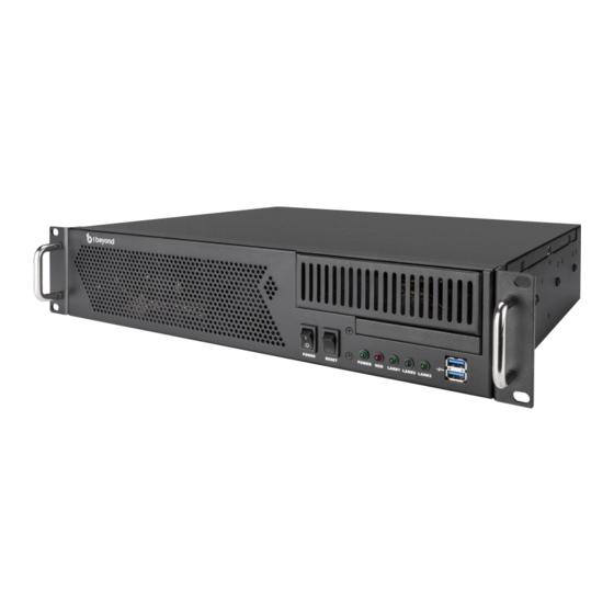
Physical Description The camera switching device provides the following connectors and indicators. IV-SAM-VXP-1B Connectors and Indicators IV-SAM-VXN-1B Connectors and Indicators IV-SAM-VXS-1B Connectors and Indicators Name Description Power AC power BIOS Flashback Button Not used Wi-Fi Connects the antenna to the onboard Wi-Fi™ network chip HDMI® Not used USB 3.2 Gen 1 2x USB Type-A ports for peripheral device connections... - Page 17 Name Description Audio Connections Orange: Central/bass speaker out Blue: Line in Black: Rear speaker out Green: Headphone/speaker out Pink: Microphone in Optical: Optical SPDIF out NIC 1 1 Gbps RJ-45 Ethernet port USB 3.2 Gen1 USB Type-A port for peripheral device connections USB 3.2 Gen2 USB Type-C® port for faster data rates Thunderbolt™...
-
Page 18: Specifications
Specifications Refer to the following sections for more information on the specifications for various 1 Beyond Automate™ VX models. IV-SAM-VXS-1B Specifications on page 14 IV-SAM-VXN-1B Specifications on page 16 IV-SAM-VXP-1B Specifications on page 18 Product Manual — Doc. 9324F IV-SAM-VXN-1B, IV-SAM-VXP-1B, and IV-SAM-VXS-1B • 13... -
Page 19: Iv-Sam-Vxs-1B Specifications
IV-SAM-VXS-1B Specifications Product specifications for the IV-SAM-VXS-1B are provided below. Product Specifications Automate VX Capabilities Titles, Graphics, Layouts Titles, logos, backgrounds can be added, Easy-to-use graphic designer to create any multi-source layout Program Record MP4 file (H.264 codec). User-selectable bitrate up to 10 Mbps Recording Capacity Records to internal 500 GB SSD storage Streaming Encoder... - Page 20 Height 3.5 in. (89 mm) Width 16.75 in. (425 mm) Depth 14.5 in. (368 mm) Weight 14 lb (6.35 kg) Product Manual — Doc. 9324F IV-SAM-VXN-1B, IV-SAM-VXP-1B, and IV-SAM-VXS-1B • 15...
-
Page 21: Iv-Sam-Vxn-1B Specifications
IV-SAM-VXN-1B Specifications Product specifications for the IV-SAM-VXN-1B are provided below. Product Specifications Automate VX Plus Capabilities Titles, Graphics, Layouts Titles, logos, backgrounds can be added, Easy-to-use graphic designer to create any multi-source layout Program Record MP4 file (H.264 codec). User-selectable bitrate up to 10 Mbps Recording Capacity Records to internal 500 GB SSD storage Streaming Encoder... - Page 22 Height 3.5 in. (89 mm) Width 16.75 in. (425 mm) Depth 14.5 in. (368 mm) Weight 14 lb (6.35 kg) 17 • IV-SAM-VXN-1B, IV-SAM-VXP-1B, and IV-SAM-VXS-1B Product Manual — Doc. 9324F...
-
Page 23: Iv-Sam-Vxp-1B Specifications
IV-SAM-VXP-1B Specifications Product specifications for the IV-SAM-VXP-1B are provided below. Product Specifications Automate VX Pro Capabilities Titles, Graphics, Layouts Titles, logos, backgrounds can be added, Easy-to-use graphic designer to create any multi-source layout Program Record MP4 file (H.264 codec). User-selectable bitrate up to 10 Mbps Recording Capacity Records to internal 1 TB SSD storage Streaming Encoder... - Page 24 Height 3.5 in. (89 mm) Width 16.75 in. (425 mm) Depth 14.5 in. (368 mm) Weight 14 lb (6.35 kg) 19 • IV-SAM-VXN-1B, IV-SAM-VXP-1B, and IV-SAM-VXS-1B Product Manual — Doc. 9324F...
-
Page 25: Installation
Installation Use the following procedures to install the Automate VX. In the Box Qty. Description IV-SAM-VXS-1B, IV-SAM-VXN-1B, or IV-SAM-VXP-1B Automate™ VX Camera Switcher Additional Items Rail, 20 in. (508 mm) (2060809) Power Supply, 400 W (2060806) Power Cord, IEC (2060805) Wi-Fi™ Network Antenna SDI to HDMI® Signal Converter (2060804) Feet Set, Chassis (2060809) IV-SAM-VXS-1B and IV-SAM-VXP-1B Only... -
Page 26: Connect To The System
3. Connect each PTZ camera to the SDI® ports of the Automate VX device using HD-SDI cables. Ensure the numbered SDI port corresponds to the camera number determined in step 1. NOTE: Each PTZ camera should be connected to a network switch via Ethernet and can be powered via PoE+ (Power over Ethernet Plus) with 30 W power. - Page 27 3. Connect to the camera switching device in the remote desktop client using the following IP address: 10.1.10.2. Remote Desktop Client Login 4. When prompted, enter the following default login credentials: Username: Valued Customer Password: 1beyond NOTE: This Username and Password above are also the Windows system login credentials. Product Manual —...
-
Page 28: Configuration
Configuration Use the following procedures to configure the Automate VX. This section provides the following information: Initial Setup on page 24 Room Designer on page 29 System Configuration on page 93 Wirecast Configuration on page 112 23 • IV-SAM-VXN-1B, IV-SAM-VXP-1B, and IV-SAM-VXS-1B Product Manual —... -
Page 29: Initial Setup
Initial Setup Use the following procedures to set up the Automate VX following installation. Assign Network Interfaces Automate VX has two NICs labeled Ethernet and Ethernet 2. The Ethernet ports have the following default addressing configuration: The NIC 1 port is set as a static IP (10.1.10.2) for initial configuration via the Windows® Remote Desktop application. - Page 30 Depending on your network configuration, either reserve the DHCP IP address in the network router or set static IP addresses individually on each NIC. Static IP addresses can be set in the Windows Network & Internet settings. Windows Internet & Network Settings Assigning IP addresses for 1 Beyond cameras must be done through the 1 Beyond Camera Manager.
-
Page 31: Use Remote Support
Use Remote Support Automate VX can be configured from a laptop on the same subnet as the system using the web browser interface. For advanced configurations, Windows Remote Desktop can be used. 1 Beyond Camera Systems Remote Professional Services will access the Automate VX using TeamViewer. TeamViewer Quick Support is installed on the Automate VX's desktop for remote access and will require the system to be connected to the internet. -
Page 32: Update Firmware
Update Firmware Automate VX can be updated with firmware provided by Crestron. To update an Automate VX's firmware: NOTE: Wirecast is automatically updated with the Automate VX firmware installer if the system has an active Wirecast license. The license expiration date is located in the File menu of Wirecast (File >... - Page 33 VX. Automate VX stores a backup of the previous firmware and settings that were present at the time of the upgrade. To revert the system to a previously used state, contact Crestron True Blue Support. b. Press the U key on the keyboard to update the Automate VX system with the new firmware.
-
Page 34: Room Designer
Room Designer Automate VX contains the Room Designer tool that uses the scaled floor plan (in the form of an image) to create a framework for how the Automate VX operates. Automate VX relies on audio gating or positional information provided by third-party devices in order to determine where an active speaking participant is located in a room. - Page 35 NOTE: The 1beyond password above will only work on the first login to Automate VX. Automate VX prompts a password change, enter a new password as directed. 2. Select Login. NOTE: The login credentials are for the admin user. For any other users, use the username and password of the other user to login.
- Page 36 The web configuration interface is displayed with the Main tab open by default. To access Room Designer from the Main tab, select the pencil icon in the top right of the menus. Main View to Room Designer 31 • IV-SAM-VXN-1B, IV-SAM-VXP-1B, and IV-SAM-VXS-1B Product Manual —...
- Page 37 The Room Designer page is displayed. Room Designer Default Page Product Manual — Doc. 9324F IV-SAM-VXN-1B, IV-SAM-VXP-1B, and IV-SAM-VXS-1B • 32...
-
Page 38: Floor Plan Upload
Floor Plan Upload Room Designer by default comes with a demo layout tied to Configuration 1. This is only a template and should not be used as an actual room layout. To upload a floor plan for a room design: 1. - Page 39 To upload a Room Designer project into the Automate VX: 1. Ensure that the project to be uploaded is located in a file directory on the Automate VX. 2. Select the Choose File button under the Upload Project banner. This will open a file explorer window.
-
Page 40: Configure A Room Designer Project
Configure a Room Designer Project The following settings are provided for configuring a Room Designer project. General Settings Select the Settings tab on the left-hand side of the Room Designer page to access the following general Room Designer settings. Settings Tab Set Scale Set the scale for the room to provide the Automate VX a reference to the room size. - Page 41 4. Move the mouse cursor to the other end of the object that is being used as a reference. Ensure that the red line is straight, then click on the endpoint of the reference object. CAUTION: Ensure that this process is done accurately and precisely. If the reference object was not measured correctly, then the performance of the Automate VX may suffer.
- Page 42 6. Select Ok to confirm the measurement. This will create a 2 ft by 2 ft (60 mm by 60 mm) grid that is set to the size and scale of the room to appear on the room layout. The grid will automatically appear as an overlay on the room layout when the measurement is confirmed.
- Page 43 Add Camera Device Select Add Camera Device to add a pentagon-shaped object at the top left of the room layout that designates a camera within the room. Place a Camera Device in each location where there is a camera within the room layout. The cameras are numbered in the order they are added. For more information, refer to Configuring Camera Devices on page 52 Camera Device...
- Page 44 When using a DSP such as Biamp Tesira™, QSC Q-Sys™ Core, or Shure IntelliMix™ Room as a Microphone Device, the placement of the square does not matter, and it will not affect the Automate VX. Virtual Mics should match the positions of the individual microphones in the room. For more information, refer to Configuring Virtual Mics and Blocking Zones on page Microphone Device...
- Page 45 When the Default Shot is selected, the settings appear in the right-hand menu and follow the same configuration parameters as Virtual Mics. For more information on the right-hand menu and the Virtual Mic settings, refer to Virtual Mic Settings on page 75 Default Shot Shift Grid ...
- Page 46 NOTE: Shifting the grid will not affect the scaling, it will remain as a 2 ft by 2 ft (60 mm by 60 mm) grid regardless of the grid's placement. Remove Camera Device Select Remove Camera Device to remove a Camera Device from the configuration and room layout. Camera Devices are removed in reverse numerical order (4, 3, 2, then 1) with this option.
- Page 47 Units Enable Units to change the units used in Room Designer from imperial units (inches) to metric (millimeters). Disabling this option will revert the units from metric (millimeters) to imperial (inches). The current unit type is indicated by the parentheses next to the Units option. Units in Imperial (inches) Units in Metric (mm) Product Manual —...
- Page 48 Shot Visualization Enable Shot Visualization to show which Camera Devices are aimed at a particular Virtual Mic position (or Default Shot). A cone will go from the Camera Device to the Virtual Mic position, and the size of the cone will coincide with the Shot Width. For more information on configuring Virtual Mics with Camera Devices, refer to Configuring Virtual Mics and Blocking Zones on page 70 Shot Visualization...
- Page 49 Mic Visualization Enable Mic Visualization to show which Virtual Mics are associated with the selected Microphone Device. It will be displayed with an orange line going from the Microphone Device to the Virtual Mics. This tool is useful when there's an overlap between two or more Virtual Mics. Mic Visualization Live Mode Enable Live Mode to display a grid view in Wirecast to show all live Camera Device feeds at once.
- Page 50 Proximity Check Enable Proximity Check to show if Virtual Mics are too close to other Virtual Mics, or if they are out of range from the Microphone Device. If any of these apply, they will be indicated in the room layout with a dashed red line.
- Page 51 Show Global Mic # By default, Room Designer numbers the Virtual Mics and Blocking Zones in the system separately based on their connected Microphone Device. Global Mic # OFF Enable Show Global Mic # to show the total number of virtual mics and blocking zones. Global Mic # ON Product Manual —...
- Page 52 Show Origin Enable Show Origin to have the origin point visible in the room layout. The origin point is the reference point that is used for all of the coordinates used inside of Room Designer (Camera Devices, Microphone Devices, and Virtual Mic locations). The origin point is indicated by the red circle with a dot in the room layout.
- Page 53 Show Ruler Enable Show Ruler to display a ruler on the top and left of the room layout. The ruler will use the corresponding unit from the Units option (inches or millimeters). The 0,0 position on the ruler is determined by the origin point. Ruler Overlay The ruler displays red lines as the X and Y coordinates indicating where the cursor is in the room layout.
- Page 54 Show Mic Coverage Enable Show Mic Coverage to show the circular range of Virtual Mic positions. This range indicates the area where the Microphone Device will switch the camera feed to the Virtual Mic's location when audio is detected. NOTE: The Mic Coverage feature is only applicable to the Shure MXA920 XYZ, Sennheiser TCC2, Audio Techinica®...
- Page 55 Use the text field to input a Virtual Mic radius or use the slider to adjust the radius. Change the Virtual Mic radius to fine-tune Virtual Mic locations so that there is no overlap between positions. Virtual Mic Coverage Radius Product Manual —...
- Page 56 Adjudicator Settings Select the Adjudicator tab on the left-hand side of the Room Designer page to access the following room adjudicator settings. Adjudicator Tab To enable the adjudicator, turn on the Enabled toggle. This should be enabled when there is a DSP involved with the room configuration.
-
Page 57: Configuring Camera Devices
Notes Page Select the Notes tab on the left-hand side of the Room Designer page to access the notes page. Information or any notes about the current room configuration can be placed here and will be saved for future use. Configuring Camera Devices Camera Devices are the camera outputs that the Automate VX uses to display the camera feed. - Page 58 Once the Camera Devices are placed in the room layout, select a Camera Device to open the Camera Device Settings. This panel will appear on the right side of the screen. Camera Device Settings 53 • IV-SAM-VXN-1B, IV-SAM-VXP-1B, and IV-SAM-VXS-1B Product Manual —...
- Page 59 The following Camera Device settings are available. Remove Camera Select the Remove Camera button to remove the selected Camera Device from the current configuration. This removes all settings associated with the Camera Device from the configuration. Remove Camera Button Product Manual — Doc. 9324F IV-SAM-VXN-1B, IV-SAM-VXP-1B, and IV-SAM-VXS-1B •...
- Page 60 Model Select the drop-down menu under the Model title to select the camera model for the respective Camera Device. This should match the same model that was used in the physical room. Camera Device Model Menu The following camera models are available. generic: Select this model when the camera model being used is not a PTZ-12, PTZ-20, or an AutoTracker 3 camera.
- Page 61 AT: Select this model when the camera model being used is a 1 Beyond AutoTracker 3 camera. These cameras do not need to have their PTZ controls (Position and Orientation controls) changed, the AutoTracker 3 does the tracking internally. AutoTracker 3 cameras are shown in Room Designer as an orange pentagon instead of a yellow pentagon.
- Page 62 Network Enter the IP address of the camera that is being used as the Camera Device in the IP text field. 1 Beyond cameras IP addresses can be obtained and changed in the 1 Beyond Camera Manager. For more information about the 1 Beyond Camera Manager, refer to the 1 Beyond Camera Manager Product Manual.
- Page 63 Position The X, Y, and Z fields are the coordinates of the Camera Device in the room layout. Enter the coordinates of the Camera Device into their respective fields, or drag the Camera Device and place it into the correct location. The units used in the text fields are either in inches or millimeters, depending on the unit selected in the View tab. For more information about changing the units, refer to Units on page NOTE: The X, Y, and Z coordinates of the Camera Device are measured relative to the set Origin...
- Page 64 Orientation The Pan, Tilt, and Roll text fields indicate the direction the Camera Device's lens is facing when it is in the default (resting) state. The direction that the camera lens is facing is indicated by the blue LENS box. LENS is the bird-eye view of the top of the camera, and the orientation of the blue box should match the way the camera is set up in the physical room.
- Page 65 The handle sticking out of the Camera Device in the room layout can also adjust the Pan setting of the camera. Click and hold the handle to change this value. NOTE: When adjusting the Camera Device Orientation, the Camera Device handle corresponds with the camera lens when the lens is facing forward.
-
Page 66: Configuring Microphone Devices
Configuring Microphone Devices Microphone Devices are the microphones in a room that the Automate VX uses to receive audio from active-speaking participants. Microphone Devices are indicated in room designer as square-shaped nodes. For more information about adding Microphone Devices to a room layout, refer to Microphone Device on page 38 There are three different types of microphones, and each microphone type is configured differently within Room Designer. - Page 67 The following Microphone Device settings are available. Remove Mic Device Select the Remove Mic Device button to remove the selected Microphone Device from the current configuration. This removes all settings associated with the Camera Device from the configuration. Remove Mic Device Button Product Manual —...
- Page 68 Model Select the drop-down menu under the Model title to select the microphone model for the respective Microphone Device. This should match the same model that was used in the physical room. The following microphone models are available: Audio Techinica® ATND1061 (beta) Biamp Tesira generic QSC Q-SYS™...
- Page 69 Microphone Device Model Menu NOTES: If the microphone that is being used in the room is not one of the models listed above, then select generic. Generic microphones may not operate properly with the Automate VX. When using the Shure MXA920-Lobe or Shure MXA910 as the Microphone Device, the Virtual Mic positions should match the locations of the lobes in the Shure Designer Configuration software.
- Page 70 Network Enter the IP address of the microphone in the IP text field. This allows Automate VX to connect and communicate with the microphone. Microphone Device Network Setting 65 • IV-SAM-VXN-1B, IV-SAM-VXP-1B, and IV-SAM-VXS-1B Product Manual — Doc. 9324F...
- Page 71 Position The X, Y, and Z fields are the coordinates of the Microphone Device in the room layout. Enter the coordinates of the Microphone Device into their respective fields, or drag the Microphone Device and place it into the correct location. The units used in the text fields are either in inches or millimeters, depending on the unit selected in the View tab.
- Page 72 Orientation The Pan field indicates the direction that the microphone is facing. Change the value in the Pan field to match the Microphone Device to the physical microphone. Microphone Device Orientation Setting 67 • IV-SAM-VXN-1B, IV-SAM-VXP-1B, and IV-SAM-VXS-1B Product Manual — Doc. 9324F...
- Page 73 Alternatively, the handle attached to the Microphone Device can rotate the microphone. This will automatically change the value in the Pan field to reflect the orientation. Microphone Device Handle For optimal microphone performance, the Microphone Device should be oriented with the handle extending in the same direction as the manufacturer logo on the physical microphone.
- Page 74 Noise Threshold Use the slider under the Noise Threshold setting to adjust the RMS (Root Mean Square) value of the Microphone Device. The text field below the slider can also be used to manually input an RMS value. NOTE: Noise Threshold is only applicable to the Shure MXA920 XYZ Mode, Sennheiser TCC2, and Yamaha ADECIA microphones.
-
Page 75: Configuring Virtual Mics And Blocking Zones
Duplicate Device Select the Duplicate Device button to create a copy of the currently selected Microphone Device. Once the button is clicked, click again in the desired location for the copied Microphone Device. This also duplicates all Virtual Mic positions, Blocking Zone positions, and Adjudicator settings as well. Microphone Device Duplicate Device Setting Configuring Virtual Mics and Blocking Zones Virtual Mics represent the active speaking participants positions in Room Designer. - Page 76 To use Virtual Mic settings in a room layout: 1. Select the Microphone Device that is going to be tracking audio. The Microphone Device Settings menu appears on the right side of the window. Microphone Device Settings 71 • IV-SAM-VXN-1B, IV-SAM-VXP-1B, and IV-SAM-VXS-1B Product Manual —...
- Page 77 2. Navigate to the Mics section of the Microphone Device Settings menu. Microphone Device Settings: Mics Product Manual — Doc. 9324F IV-SAM-VXN-1B, IV-SAM-VXP-1B, and IV-SAM-VXS-1B • 72...
- Page 78 The following Virtual Mic settings are available. Add Virtual Mic Select Add Virtual Mic to add a Virtual Mic to the room layout. The Virtual Mic will be placed directly on top of the Microphone Device. Click and drag the Virtual Mic to the position where an active speaking participant would be in the room layout.
- Page 79 Remove Virtual Mic Select Remove Virtual Mic to delete a Virtual Mic in the room layout. This will delete the highest numbered Virtual Mic associated with the Microphone Device (10, 9, then 8, and so forth). Add Blocking Zone A Blocking Zone is used to mute a Microphone Device that might pick up unwanted ambient audio. This is particularly useful when there is an ambient sound in the room (vents, AC unit, and so forth).
- Page 80 Virtual Mic Settings Once a Virtual Mic is placed in the correct location, select the Virtual Mic to open the Virtual Mic Settings. The menu will appear on the right side of the screen. Virtual Mic Settings The following Virtual Mic settings are available in this menu: Remove Virtual Mic Select Remove Virtual Mic to delete the currently selected Virtual Mic.
- Page 81 Position The X, Y, and Z fields are the locations of the Virtual Mic in the room layout. These coordinates can be entered manually into their respective fields, or the Virtual Mic can be dragged and placed into the correct location. The units used in the text fields are either in inches or millimeters depending on the unit selected in the View tab.
- Page 82 Cameras There are two separate drop-down menus under the Cameras title: one for Primary and one for Secondary. These drop-down menus are provided for cameras that will be showing the Virtual Mic position through the camera feed. Select the desired camera that will be broadcasting the Virtual Mic location in the Primary drop-down menu, and select a backup camera for the Virtual Mic in the Secondary drop-down menu.
- Page 83 Shot Width Use the Shot Width slider or input a value into the text field to change the size of the camera shot. Enable Shot Visualization in the View tab to see the size of the camera shot in the room layout. Enable Live Mode in the View tab to see how the Shot Width affects the camera shot in real-time on Wirecast.
- Page 84 SuperLobe A SuperLobe contains a group of Virtual Mic positions. The grouped Virtual Mic positions associated with the SuperLobe are SubLobes. When the Microphone Device detects audio from a SubLobe, the Camera Device will set the camera shot on the SuperLobe position rather than the specific SubLobe position.
- Page 85 In the following example, the Virtual Mic positions do not pass the Proximity Check (indicated by red lines between Virtual Mic positions). Virtual Mic 11 is the SuperLobe, and Virtual Mics 3 and 4 are SubLobes. The camera uses Virtual Mic 11 to create a single camera shot displaying all three of the Virtual Mic positions.
- Page 86 Identify SuperLobes and SubLobes by selecting a Virtual Mic position. Select a SuperLobe to display all SubLobes with a red outline around the Virtual Mic positions. SuperLobe Selected Select a Sublobe to display the SuperLobe that it is grouped with. A green outline is displayed around the SuperLobe Virtual Mic position.
- Page 87 Chairman Mic Enable Chairman Mic to make the currently selected Virtual Mic a chairman. This means that whenever audio is picked up from this Virtual Mic location, it will take priority over the other Virtual Mic positions. The camera shot switches to that Virtual Mic position regardless of audio signals from other Virtual Mic positions.
- Page 88 PTZ Control PTZ controls adjust how a camera will display the Virtual Mic position. For the best results, enable Live Mode in the View tab to see how these settings change the camera shot in Wirecast. Virtual Mic PTZ Controls The PTZ Control switch indicates which camera is being edited. By default, the switch is set to the Primary camera (in the pictured example, 3 is the Primary camera).
- Page 89 2. Locate the Adjudicator setting in the Microphone Device settings menu. Adjudicator Setting 3. In the Channel text field, input the desired channel that will be used for communication between the microphone and the adjudicator. Ensure each Microphone Device is on its own channel. Automate VX will not operate properly if multiple Microphone Devices are on the same channel.
- Page 90 3. Create two (or more) Virtual Mics, and place them in the exact locations where standard microphones are in the room. These Virtual Mics occupy Channel 1 and 2 respectively, but do not need to be set in Automate VX. For more information about creating Virtual Mics, refer to Virtual Mic on page NOTE: For more than two standard microphones, place additional Virtual Mics with subsequent Channel numbers.
-
Page 91: Autoswitch Preview
AutoSwitch Preview The AutoSwitch Preview setting shows live positional data from audio sources within the room layout. To enable AutoSwitch Preview, select the Save and Start AutoSwitch button in the top left of Room Designer. Save and Start AutoSwitch Preview Product Manual —... - Page 92 The button displays Stop AutoSwitch if AutoSwitching is currently on for the system. Select Stop AutoSwitch to turn off AutoSwitching. AutoSwitch Preview is only available if AutoSwitching is turned off. NOTE: The Stop AutoSwitch button turns off AutoSwitching, but this can be done through the Main tab too.
- Page 93 Enable AutoSwitch Preview to have Microphone Devices display the location of audio within the room. This is indicated with lines extending from the Microphone Devices towards the location where audio is heard. The color of the line indicates which Microphone Device is associated with the line (a blue line is tied to Microphone Device 1, a green line is tied to Microphone Device 2, and so forth).
- Page 94 If the line extending from the Microphone Device has dashes, the audio the Microphone Device is detecting is out of range of the nearest Virtual Mic coverage area. For more information about Virtual Mic coverage, refer to Show Mic Coverage on page 49 NOTE: The end of the line extending from the Microphone Device is associated with the height of the nearest Virtual Mic position.
- Page 95 The circle around the Virtual Mic position displays whether the speaker was audible for long enough for the Noise Delay threshold to be met. For more information regarding Noise Delay, refer to AutoSwitch Settings on page 101. If the circle around the Virtual Mic position is solid, then the Noise Delay threshold was met. If the circle around the Virtual Mic position is hollow, then the Noise Delay threshold was not met.
- Page 96 The width of the cone extending from the Camera Device displays the current Shot Width of the camera shot. Wide Camera Shot Indicator AutoTracker 3 cameras do not have a cone that extends from the Camera Device when it is active. The AutoTracker 3 camera is indicated with a green circle around the Camera Device when the camera is active.
- Page 97 For the best performance, perform an AutoSwitch Preview test on each Virtual Mic position. This determines whether the associated microphone is accurately reading the Virtual Mic position. Verify the following items on each Virtual Mic position with AutoSwitch Preview: 1. Confirm the Virtual Mic is in range of the Microphone Device. The line extending from the Microphone Device should be a solid line (not a dashed line) when interacting with the Virtual Mic position.
-
Page 98: System Configuration
NOTE: Most system configurations can be accomplished by using the Intelligent Video Room Designer tool. This tool is available on the Crestron website and locally on the Automate VX. For more information on using the tool, refer to Room Designer on page 29 Access the Web Configuration Interface To access the web configuration interface for the Automate VX, open the Chrome®... - Page 99 NOTE: The log in credentials are for the admin user. For any other users, use the username and password of the other user to login. For more information, refer to Add User on page 110. The web configuration interface is displayed with the Main tab open by default. NOTE: The Main tab is also where the operation of the Automate VX occurs.
- Page 100 To access the system settings: 1. Select the pencil icon on the top right of the page to open Room Designer. Main Tab to Room Designer 95 • IV-SAM-VXN-1B, IV-SAM-VXP-1B, and IV-SAM-VXS-1B Product Manual — Doc. 9324F...
-
Page 101: General Settings
2. Select the gear icon at the top right of the page to open the system settings. Room Designer Page When trying to access the system settings anywhere else besides the Main tab, the gear icon is present. General Settings Select the General tab to view the available general system settings. - Page 102 Output Settings The following settings are used to turn the available camera outputs on and off, and to select the desired resolution for each output. Output Settings Three output settings are provided that can be turned on or off: SDI, NDI, and Virtual Camera. Each output has a drop-down menu with the following resolution output options: NTSC 1080i 50...
- Page 103 Layout Settings Layouts are a way of switching between different composite shots. Composite shots are camera shots with multiple video layers. Layout Settings Each layout is given an ID (A to Z) and can be named by selecting the appropriate Layout Name text field.
- Page 104 Select the Enabling Pause check box to provide pausing functionality during recording. Pausing will create incomplete recordings which are stored in D:/Recording_Temp. Once a recording has been stopped, the incomplete recordings are joined into a complete recording and saved in D:/Recordings. Sleep and Wake Settings The following sleep and wake settings are provided.
- Page 105 NOTE: Automate VX reboots daily to better the performance of the system. The system will perform the action selected for Startup Action upon reinitialization. Push-to-Talk Settings The following push-to-talk settings are provided. Push-to-Talk Settings Select the Enable Side by Side check box to turn on side-by-side shots. A side-by-side shot is a split screen shot that captures two active participants who are speaking mostly at the same time.
-
Page 106: Titling Settings
AutoSwitch Settings The following AutoSwitch settings are provided. Auto Switch Settings Switch Delay: Determines how long it will take the system to switch to a camera shot. Increasing this value will help prevent camera movement during AutoSwitching. Noise Delay: Determines how long a noise needs to occur before the system recognizes it. This feature helps to avoid switching based on coughs or other short sounds. - Page 107 Microphone Table The Microphone Table shows the relationship between microphone devices and virtual microphones in the system. The Device Number column indicates the microphone device and the Mic Number column shows the virtual microphone associated with the microphone device. Microphone Table Microphone Devices are configured through Room Designer.
- Page 108 Selecting the check box next to the Enable Titling setting will allow one of the following three selections to be available: Select Static Titling from Settings to add a third column to the Microphone Table for entering titles manually. Microphone Table - Static Title Column Select Dynamic Titling from Mic.
-
Page 109: Scenario Settings
Scenario Settings Select the Scenarios tab to view the available scenario settings. The Scenario Settings show the currently available scenarios for the system. Scenario Settings To add additional scenarios, select Add Scenario. A new scenario will be added with the next available numbered ID. -
Page 110: Advanced Settings
NOTE: Ensure that projects are saved within Room Designer and exported to a local drive before removing configurations. If a configuration is unintentionally removed and needs to be restored, contact Crestron True Blue Support. To change the name of a configuration, it must be done within Room Designer. For more information,... - Page 111 Selecting a room configuration can also be called with an API or Crestron command. For more information on using the Automate VX API, refer to the appropriate documentation at https://developer.crestron.com. Load Microphone Device Preset When using multiple room configurations, it is possible to load corresponding presets for Shure Intellimix Devices such as MXA910, MXA310, P300, and Intellimix Room.
- Page 112 Select the Delete files from source after copying check box to remove files from D:\Recordings\VX after a successful copy. When unchecked, copied files are moved to D:\RecordingsDone. Video Production Server Settings The following video production settings are provided. Video Production Server Settings Select the Enable Wirecast check box to enable communication between the Automate VX system and Wirecast.
-
Page 113: Admin And User Settings
Admin and User Settings Admin and User settings are accessible by selecting the Users icon at the top right of the page while logged in as an admin. Users Icon The admin user has full access to all settings. New users can be created with full or limited access to system settings. - Page 114 Permissions Select the Permissions tab to set permissions for additional users in the system. For example, an end user could be given permission only to operate the AutoSwitch feature. Additional users will need to be created using the Add User settings to change permissions for other users. For more information, refer Add User on page 110.
- Page 115 Add User The following settings to add a user are provided. User Settings - Add User Select the Add User tab to add a new user. Enter the new username and password in the appropriate text fields, then select Add User. Change Password Select the Change Password tab to update the password for an existing user.
- Page 116 Delete User The following settings to delete a user are provided. User Settings - Delete User Select the Delete User tab to delete an existing user. Enter the username of the user to delete, then select Delete User. 111 • IV-SAM-VXN-1B, IV-SAM-VXP-1B, and IV-SAM-VXS-1B Product Manual —...
-
Page 117: Wirecast Configuration
Wirecast Configuration Automate VX uses Wirecast® streaming software to change live shots, layouts, and output. During initial setup, changes may need to be made to the Wirecast document to customize the system, such as setting custom layouts with logos. The Wirecast document is located within C:\Program Files\1 Beyond\Automate Project.wcst. -
Page 118: Create Layouts
Side-by-Side Wirecast Shots When creating side-by-side shots in the Wirecast document, place the first camera on the left and the second camera on the right. Add Titles Titles are placed in shots in the layer above the basic and side-by-side shots. Each layout has a regular title and a side-by-side title (for example, A_Title and A_Title_S). -
Page 119: Configure Audio
Configure Audio Audio input to the Automate VX is not required for voice-activated camera switching. For video conferencing, send audio directly from your DSP to your codec with a 400ms delay in order to ensure proper lip sync. For local recording or streaming with the system, activate the installed Dante Virtual Soundcard by purchasing a license from www.audinate.com. - Page 120 1. Select the Schematic Elements menu. The Schematic Elements menu opens, and the Components menu is displayed. 115 • IV-SAM-VXN-1B, IV-SAM-VXP-1B, and IV-SAM-VXS-1B Product Manual — Doc. 9324F...
- Page 121 2. Select Audio Components to show more components, then select Mixers to expand the Mixers menu. Product Manual — Doc. 9324F IV-SAM-VXN-1B, IV-SAM-VXP-1B, and IV-SAM-VXS-1B • 116...
- Page 122 Audio Components Menu 117 • IV-SAM-VXN-1B, IV-SAM-VXP-1B, and IV-SAM-VXS-1B Product Manual — Doc. 9324F...
- Page 123 3. In the Mixers menu, select Gating Automatic Mic Mixers. The Gating Automatic Mic Mixers menu opens. Product Manual — Doc. 9324F IV-SAM-VXN-1B, IV-SAM-VXP-1B, and IV-SAM-VXS-1B • 118...
- Page 124 4. Click and hold the left mouse button on Absolute Threshold (Legacy), then drag Absolute Threshold (Legacy) into the project. Release the left mouse button to insert the Gating Automatic Mic Mixer (Legacy) block into the project. Gating Mixer Block 119 •...
- Page 125 Gating Mixer Properties The properties of the gating mixer block must be changed to communicate with Automate VX. To set the properties of the gating mixer block: 1. Select the Gating Automatic Mic Mixer (Legacy) block, then select Properties. NOTE: The Gating Automatic Mic Mixer (Legacy) block is the Absolute Threshold (Legacy) component from the previous section.
- Page 126 2. In the Properties menu, select the Channels text field. Input the same number of channels used in the AutoSwitching configuration. For more information about channels in Automate VX, refer to Configuring Adjudicators on page 121 • IV-SAM-VXN-1B, IV-SAM-VXP-1B, and IV-SAM-VXS-1B Product Manual —...
- Page 127 3. In the Properties menu, use the Code Name text field to change the gating mixer code name to 1Beyond:GatingAutomaticMicMixer(Legacy). For Q-SYS Designer software versions 9.5 and prior, change the code name of the gating mixer to 1Beyond. Product Manual — Doc. 9324F IV-SAM-VXN-1B, IV-SAM-VXP-1B, and IV-SAM-VXS-1B •...
- Page 128 NOTES: The Gating Automatic Mic Mixer (Legacy) is a separate, but parallel gating mixer to the one used for audio processing. The audio is routed into the gating mixer after AEC and room mutes, but before other audio processing (EQ, compression, and so forth). Gating Mixer in Project Named Controls The channels of the gating mixer require a specific naming convention to communicate with Automate...
- Page 129 1. Double-click the left mouse button on the Gating Automatic Mic Mixer (Legacy) block. The mixer block settings window is displayed. NOTE: The Gating Automatic Mic Mixer (Legacy) block requires the code name 1Beyond:GatingAutomaticMicMixer(Legacy). For more information on gating mixer properties, refer to Gating Mixer Properties on page 120 Mixer Block Selection...
- Page 130 2. Select Named Controls on the bottom left side of the software screen. This expands the Named Controls menu. 3. In the mixer blocks settings window, click and hold the left mouse button on an open gate and drag the gate into the named controls. Do this step for each open gate. Each channel within the named controls should have the name 1Beyond:GatingAutomaticMicMixer(Legacy)channel#open.
- Page 131 Settings Certain settings of the gating mixer block provide a better AutoSwitching experience with Automate VX. Complete the following procedure to configure the settings of the gating mixer block: 1. Double-click the left mouse button on the Gating Automatic Mic Mixer (Legacy) block. The mixer block settings window is displayed.
- Page 132 2. Select File in the top left corner of the software screen. Then, select Emulate. NOTE: Alternately, press the F6 button on the keyboard to activate Emulate. 3. In the mixer block settings window, select the Hold time dial. Then, type 250 on the keyboard to set the Hold Time to 250 ms for all channels.
- Page 133 4. In the mixer block settings window, use the Max NOM text field to set the NOM (Number of Open Mics) to 2 or 3 depending on the number of channels. For more information about channels in Automate VX, refer to Configuring Adjudicators on page 5.
- Page 134 AEC Reference If a ceiling array microphone is in the room, an AEC (Acoustic Echo Cancellation) reference must be sent for the ceiling array microphone. If there are multiple ceiling array microphones, ensure that an AEC reference is sent for each ceiling array microphone. For more information about ceiling array microphones, refer to Configuring Microphone Devices on page 61 AEC Reference Example...
- Page 135 Delay Block A delay block is required in the project for the audio to properly sync with the video output from Automate VX. To add and configure a delay block into the project: 1. In the Schematic Elements menu, click and hold the left mouse button on Delay. Then, drag Delay into the project and release the left mouse button.
- Page 136 2. Select the Standard Delay block to open the mixer block settings window. 3. Select File in the top left corner of the software screen. Then, select Emulate. NOTE: Alternately, press the F6 button on the keyboard to activate Emulate. 131 •...
- Page 137 4. In the mixer block settings window, select the Delay dial. Then, type 400 on the keyboard to set the Delay to 400 ms. This ensures that the sync with the Automate VX video output matches. NOTE: If NDI cameras are used with Automate VX, the delay may need to be increased to 450ms.
-
Page 138: Biamp Tesira™ Configuration For Automate Vx
Biamp Tesira™ Configuration for Automate VX The following items are required to integrate a Biamp Tesira™ DSP with Automate VX: IV-SAM-VXS-1B, IV-SAM-VXP-1B, or IV-SAM-VXN-1B. Biamp TesiraFORTÉ™ or Biamp Tesira SERVER™. A computer with the latest version of Tesira Design software. Before configuring the Biamp Tesira DSP to communicate with Automate VX, complete the following procedure to open the Tesira Design project file: 1. - Page 139 2. Select Gating Auto Mixer, then click the left mouse button inside the project to add the Gating Auto Mixer block. The Gating Auto Mixer block appears in the project. Gating Auto Mixer Block Product Manual — Doc. 9324F IV-SAM-VXN-1B, IV-SAM-VXP-1B, and IV-SAM-VXS-1B • 134...
- Page 140 3. In the Input Channel Count drop-down menu, select the same number of channels used in the AutoSwitching configuration. For more information about channels in Automate VX, refer to Configuring Adjudicators on page 135 • IV-SAM-VXN-1B, IV-SAM-VXP-1B, and IV-SAM-VXS-1B Product Manual — Doc. 9324F...
- Page 141 NOTES: The Gating Auto Mixer is a separate, but parallel gating mixer to the one used for audio processing. The audio is routed into the gating mixer after AEC and room mutes, but before other audio processing (EQ, compression, and so forth). Gating Auto Mixer in Project Product Manual —...
- Page 142 4. Place a connection on the output of the gating mixer. Use a Signal Presenter Meter if uncertain which connection should be made. NOTE: The Tesira code will not compile without placing a connection on the output. Output Connection Example Open Mic Limits Setting the limit of open microphones at a given time provides a better AutoSwitching experience with Automate VX.
- Page 143 Complete the following procedure to configure the microphone settings of the gating mixer block: 1. Double-click the left mouse button on the Gating Auto Mixer block to open the Gating Auto Mixer settings window. Product Manual — Doc. 9324F IV-SAM-VXN-1B, IV-SAM-VXP-1B, and IV-SAM-VXS-1B • 138...
- Page 144 2. Select the mic symbol to open the Mic Options. 139 • IV-SAM-VXN-1B, IV-SAM-VXP-1B, and IV-SAM-VXS-1B Product Manual — Doc. 9324F...
- Page 145 3. Use the arrow buttons under the Open Mic Limits header to set the limit of open mics to 2 or 3 depending on the number of channels used with Automate VX. For more information about channels in Automate VX, refer to Configuring Adjudicators on page Gate Hold Time Adjusting the Gate Hold Time value eliminates accidental camera switching due to random audio during...
- Page 146 To adjust the Gate Hold Time of a gating mixer channel: 1. Select the Gating Auto Mixer block to open the Properties menu. 141 • IV-SAM-VXN-1B, IV-SAM-VXP-1B, and IV-SAM-VXS-1B Product Manual — Doc. 9324F...
- Page 147 2. Input 250 ms into the Gate Hold Time (ms) text field. Do this for all channels on the Gating Auto Mixer block. Level Block A Level block provides a better control of gating and AutoSwitching behavior with Automate VX. For more information about AutoSwitching, refer to Main Menu on page 161.
- Page 148 2. Select Level, then click the left mouse button inside the project to add the Level block. The Level block appears in the project. Level Block 143 • IV-SAM-VXN-1B, IV-SAM-VXP-1B, and IV-SAM-VXS-1B Product Manual — Doc. 9324F...
- Page 149 3. Place the Level block before the gating mixer. 4. Click and hold the left mouse button on a output node of the Level block, then drag the output node to the input node on the Gating Auto Mixer block to form a connection. Release the left mouse button once a connection is made.
- Page 150 Logic Meter Automate VX requires logic feedback from audio passing through the DSP for AutoSwitching. For more information about AutoSwitching, refer to Main Menu on page 161. To add a Logic Meter block to the project: 1. Select Logic Meter, then click the left mouse button inside the project to add the Logic Meter block.
- Page 151 2. In the Channel Count drop-down menu, select the exact amount of channels that the gating mixer has. 3. Click and hold the left mouse button on a output node of the Logic Meter block, then drag the output node to a input node on the Gating Auto Mixer block. Release the left mouse button once a connection is made.
- Page 152 5. Input 1beyond_AGM into the Instance Tag text field. This changes the instance tag of the Logic Meter to 1beyond_AGM. 147 • IV-SAM-VXN-1B, IV-SAM-VXP-1B, and IV-SAM-VXS-1B Product Manual — Doc. 9324F...
- Page 153 Enable SSH SSH (Secure Shell Protocol) must be enabled on the DSP device for Automate VX to communicate with the DSP. To enable SSH on a Biamp Tesira DSP: 1. On the top toolbar, select System to open the drop-down menu. 2.
- Page 154 3. Select the Control Network tab, then select the Enable SSH check box under the Services header. Network Settings 149 • IV-SAM-VXN-1B, IV-SAM-VXP-1B, and IV-SAM-VXS-1B Product Manual — Doc. 9324F...
- Page 155 AEC Reference If a ceiling array microphone is in the room, an AEC (Acoustic Echo Cancellation) reference must be sent for the ceiling array microphone. If there are multiple ceiling array microphones, ensure that an AEC reference is sent for each ceiling array microphone. For more information about ceiling array microphones, refer to Configuring Microphone Devices on page 61 AEC Reference Example...
- Page 156 Delay Block A delay block is required in the project for the audio to properly sync with the video output from Automate VX. To add and configure a delay block in the project: 1. On the Object Toolbar, select the Delay Components button to open the drop-down menu.
- Page 157 4. Input 400 into the Delay text field. A 400 ms delay ensures that the audio syncs with the Automate VX video output. NOTE: If NDI cameras are used with Automate VX, the delay may need to be increased to 450 ms.
-
Page 158: Shure Intellimix® Room And P300 Configuration For Automate Vx
Shure Intellimix® Room and P300 Configuration for Automate VX The following items are required to integrate a Shure Intellimix® DSP with Automate VX: IV-SAM-VXS-1B, IV-SAM-VXP-1B, or IV-SAM-VXN-1B. A computer with the latest version of Shure Intellimix® Room Audio Processing software. (Optional) A Shure IntelliMix® P300 Audio Conferencing Processor. Before configuring the Shure Intellimix DSP to communicate with Automate VX, complete the following procedure to open the Shure Intellimix®... - Page 159 3. Select the Command strings option under the Security header. Product Manual — Doc. 9324F IV-SAM-VXN-1B, IV-SAM-VXP-1B, and IV-SAM-VXS-1B • 154...
- Page 160 4. Enable Command strings by selecting the Command strings: switch to On. Automixer Settings Automixer settings in Shure Intellimix provide a better control of AutoSwitching behavior with Automate VX. For more information about AutoSwitching, refer to Main Menu on page 161.
- Page 161 To change the Automixer settings: 1. Select Automixer on the top toolbar. This opens the Automixer menu. Automixer Menu Product Manual — Doc. 9324F IV-SAM-VXN-1B, IV-SAM-VXP-1B, and IV-SAM-VXS-1B • 156...
- Page 162 2. In the Properties menu, select the Leave last mic on check box to disable the setting. Leave last mic on Enabled Leave last mic on Disabled 157 • IV-SAM-VXN-1B, IV-SAM-VXP-1B, and IV-SAM-VXS-1B Product Manual — Doc. 9324F...
- Page 163 3. Use the Maximum open channels drop-down menu to set the limit of open mics to 2 or 3 depending on the number of channels. Product Manual — Doc. 9324F IV-SAM-VXN-1B, IV-SAM-VXP-1B, and IV-SAM-VXS-1B • 158...
- Page 164 4. Input 250 into the Hold time text field. A 250 ms hold time ensures that the audio syncs with the Automate VX video output matches. NOTE: If NDI cameras are used with Automate VX, the Hold time may need to be increased to 300 ms.
-
Page 165: Operation
Operation Use the following procedures to operate the Automate VX system. This section provides the following information: Basic Operation on page 161 Camera Setup Tool on page 167 Product Manual — Doc. 9324F IV-SAM-VXN-1B, IV-SAM-VXP-1B, and IV-SAM-VXS-1B • 160... -
Page 166: Basic Operation
Basic Operation The following procedures describe how to operate the basic functions of the Automate VX. For information on how to enter the web user interface, refer to Access the Web Configuration Interface on page When the web user interface is opened, there are five main tabs that control the operation of the Automate VX system. - Page 167 A green outline is shown around the button when AutoSwitching is turned on, and will initially go to the Default Shot of the configuration. With AutoSwitching on, the system output will switch automatically based on the active speaking participant. Select AutoSwitch again to stop automated switching. NOTE: Automate VX may display an error when AutoSwitch is started.
-
Page 168: Layouts Menu
Layouts Menu Select the Layouts tab to view and select preset layouts for the Automate VX. Layouts Menu Selections To change layouts during AutoSwitch mode, select the button that corresponds with the desired layout. The layout changes immediately, and the currently active layout is highlighted in green. The layouts are only used when AutoSwitch mode is enabled. -
Page 169: Room Configs Menu
Room Configs Menu Select the Room Configs tab to view and select preset room configurations for the Automate VX. Room Configs Menu Selections To change room configurations, select the button that corresponds with the desired room configuration. The room configuration changes immediately. For more information about room configurations, refer to Room Configurations on page 105. -
Page 170: Cameras Menu
Cameras Menu Select the Cameras tab to view and select individual cameras for manual control. Cameras Menu Selections To select a camera for manual control, select a button under Cameras that corresponds to the desired camera. The live shot will change to the selected camera immediately. Use the PTZ Control settings to manually change the direction and zoom of the selected camera. -
Page 171: Scenarios Menu
Scenarios Menu Select the Scenarios tab to view and select available scenarios to choose from. Scenarios Menu Selections To change the current output to a scenario, select one of the created scenarios from the Scenarios list. This will make the current camera feed switch to the desired scenario. For more information about scenarios, refer to Scenario Settings on page 104. -
Page 172: Camera Setup Tool
Camera Setup Tool Automate VX provides a Camera Setup tool that allows microphones to be paired with a corresponding camera shot for each scenario. Scenarios are predefined camera shots that can be utilized in various situations when intelligent speaker tracking is not desired. Scenarios can also be used to define the sleep and wake actions of the Automate VX, for more information refer to Sleep and Wake Settings on page NOTE: The Camera Setup Tool can be used to view the camera shots for Virtual Mic positions within... - Page 173 To access the camera setup tool, select the camera icon within the settings page. Camera Icon Selection The Camera Setup page is displayed. Use the drop-down menu at the top of the page to change the room configuration. Then, use the drop- down menu under Camera Setup to select a virtual microphone position or a scenario.
- Page 174 The Scenario Setup page is displayed. To configure cameras in the selected scenario: 1. Select a numbered button next to the camera icon to select the cameras for the scenario. To add the cameras to the scenario, select Add to scenario when the numbered icon corresponding to the camera is highlighted green.
- Page 175 NOTE: If a non-camera shot is desired for a scenario (for example, using an image rather than a camera feed), use the Shot Layer in Wirecast to configure the camera feed for the scenario. Product Manual — Doc. 9324F IV-SAM-VXN-1B, IV-SAM-VXP-1B, and IV-SAM-VXS-1B • 170...
-
Page 176: Resources
Resources The following resources are provided for the Automate VX. NOTE: You may need to provide your Crestron.com web account credentials when prompted to access some of the following resources. Crestron Support and Training Crestron True Blue Support Crestron Resource Library Crestron Online Help (OLH) support.crestron.com/app/answers/detail/a_id/1001561... - Page 177 This page is intentionally left blank. Product Manual — Doc. 9324F IV-SAM-VXN-1B, IV-SAM-VXP-1B, and IV-SAM-VXS-1B • 172...
- Page 178 Crestron Electronics, Inc. Product Manual — Doc. 9324F 15 Volvo Drive, Rockleigh, NJ 07647 08/21/23 Tel: 888.CRESTRON Specifications subject to Fax: 201.767.7656 change without notice. www.crestron.com...
Need help?
Do you have a question about the 1 Beyond Automate VX Series and is the answer not in the manual?
Questions and answers