
Related Manuals for Anywave MPTV


Summary of Contents for Anywave MPTV
- Page 1 ANYWAVE Version 1.1 COMMUNICATION TECHNOLOGIES June 6, 2017 MPTV User Manual May 25, 2018 - Version 1.0 MEDIUM POWER VHF BAND 1 1KW TV TRANSMITTERS...
- Page 2 MPTV V1 TX User Manual Copyright Notice Copyright © Anywave Communication Technologies, Inc. 2017, All rights reserved. No part of this publication may be reproduced, translated, transcribed, stored in a retrieval system, or transmitted into any form or by any means, without the express written permission of Anywave Communication Technologies, Inc.
- Page 3 Returns and Exchanges Written approval and a Return Material Authorization number (RMA) are required from Anywave for all equipment returns. Please direct all return inquiries to the Anywave Service Department at support_us@anywavecom.com, providing the Sales Order number and Serial Number(s) of the equipment.
- Page 4 The installation, operation, maintenance and service of this equipment involves risks both to personnel and equipment and must ONLY be performed by qualified personnel exercising due care. Anywave Communication Technologies, Inc. shall not be responsible for injury or damage resulting from improper handling or from the use of improperly trained or inexperienced personnel performing such tasks.
-
Page 5: Table Of Contents
MPTV V1 TX User Manual Contents Introduction ................... 7 TX Overview ......................7 TX Specifications ....................12 AC Power Requirements ..................13 RF System Connections ..................15 TX Ventilation ......................17 Theory of Operation ..............18 Control Unit ......................20 Digital Exciter ...................... - Page 6 MPTV V1 TX User Manual TX WEB INTERFACE ..................70 PA Web Interface ....................79 Parts List ..................87 Replacement Parts – Order form ..........94 MPTV-V1-1KW-USR-DOC-V1.0, 05/25/2018 Page 6 of 96...
-
Page 7: Introduction
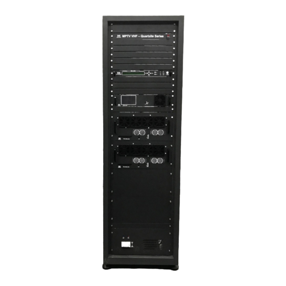
1.1 TX Overview The Anywave MPTV VHF Band 1 1kwTransmitter comes in single and dual exciter configurations. Photos of a single exciter system are shown below. The main subsystems (as seen from the front) include Exciter(s), Controller (with a touchscreen LCD, and built-in preamp), two 600W power amplifiers (4-power transistors per PA), an AC Mains Breaker, and a channel mask Band Pass Filter (BPF) –... - Page 8 MPTV V1 TX User Manual Emergency switch Exciter Controller PA 1 PA 2 Mains Breaker MPTV-V1-1KW-USR-DOC-V1.0, 05/25/2018 Page 8 of 96...
- Page 9 MPTV V1 TX User Manual From the rear view of the TX cabinet, several other main components can be seen which include an AC Distribution System, 2-way Splitter and Combiner, 2-port Directional coupler and Combiner Reject Load. Coupler Exciter Controlle...
- Page 10 MPTV V1 TX User Manual The diagram below shows the overall system interconnect between the various modules in the 2-PA MPTV system. To Ant/Load TS input Coupler To PC for Splitter Remote Ctrl Combiner RF MON RF IN Reject Load...
- Page 11 MPTV V1 TX User Manual The 2-PA MPTV system Cabinet dimensions are shown below. Please note: the BPF (not shown) is by standard mounted on top of the TX cabinet – and the additional height of the BPF must be considered in the overall system height.
-
Page 12: Tx Specifications
MPTV V1 TX User Manual 1.2 TX Specifications RF Output 1 5/8”, 50 Ω Connector: Frequency: 54MHz~88MHz (specify with order) Rated Power: 1kW (rms) (ATSC) Level Stability: < ±0.2 dB MER: > 35 dB ... -
Page 13: Ac Power Requirements
MPTV V1 TX User Manual 1.3 AC Power Requirements Please review the safety WARNINGS on page 4 of this manual before proceeding with any electrical work. A licensed Electrician is required to properly and safely connect the AC mains power cable from your stations electrical panel to the terminal block located inside the TX AC Mains Distribution compartment in compliance with local electrical and building codes. - Page 14 MPTV V1 TX User Manual The MPTV VHF TX AC distribution compartment may be wired for 240VAC single-phase (3-wire, L1, L2, GND) or 208VAC three-phase (4-wire, L1, L2, L3, GND) power to be sourced from a proper breaker sized according to the charts below. Also,...
-
Page 15: Rf System Connections
MPTV V1 TX User Manual 1.4 RF System Connections If you purchased an Anywave BPF, it is designed to be installed and mounted on top of the TX cabinet (as shown below). Four metal stand-offs “feet” with mounting hardware are supplied with the BPF to allow it to be fastened and secured to four holes located in the top panel of the cabinet. - Page 16 MPTV V1 TX User Manual Before and After BPF Directional Coupler installation Please be sure to install the Before and After BPF Directional Couplers in the correct positions and orientation. Incorrect operation of the TX system may result if these directional couplers are not installed in the proper locations with the proper orientation as labeled.
-
Page 17: Tx Ventilation
MPTV V1 TX User Manual 1.5 TX Ventilation MPTV PA cooling is from front to rear. In a standard installation, warm air is vented out perforations in the cabinet rear door and into the room. A proper air- conditioned, dust-free environment is required to operate the TX equipment. -
Page 18: Theory Of Operation
MPTV V1 TX User Manual 2. Theory of Operation The MPTV transmitter is conceptually simple to understand and easy to operate. The Transmitter operates on either 240VAC single-phase (3-wire) or 208VAC / 480VAC three-phase (4-wire) AC Mains service. An AC Mains Distribution compartment is located on the back-rear floor of the TX. - Page 19 MPTV V1 TX User Manual Additional feedback signals are provided to the Control module, which monitors these samples to implement protective protocols including forward power reduction and shutting down the TX in the event of high reflected power or other unsafe operating conditions.
-
Page 20: Control Unit
MPTV V1 TX User Manual 2.1 Control Unit TX Control Unit CTL-S-V1 consists of a pre-amp, and a powerful control system. It receives the RF input(s) from the exciter(s), performs the pre-amplification, and sends RF output to a PA or an external 2-way splitter to feed 2 PAs. The CTL-S- V1 communicates over an RS-485 serial bus to the PAs and Exciter(s) installed in the system and monitors system Forward, Reflected, and Reject load power. - Page 21 MPTV V1 TX User Manual Rear Panel The rear panel of Control Unit is shown below: RF_OUT Connector: 50 Ω Impedance: Note: Sends pre-amplified RF signal to the inputs of PA modules RF_IN_A/RF_IN_B Connector: 50 Ω...
- Page 22 MPTV V1 TX User Manual RS-485: Reserved. RS-232: Reserved. LAN: 10M/100M Ethernet port for web-based remote control (ipaddress: 192.168.1.210) AC INPUT/FUSE: 90-240 VAC Power Switch: ON/OFF MPTV-V1-1KW-USR-DOC-V1.0, 05/25/2018 Page 22 of 96...
-
Page 23: Digital Exciter
MPTV V1 TX User Manual 2.2 Digital Exciter Front Panel LCD: 40×2 LCD with power saving backlight 6 Buttons Left, Right, Up, Down, OK, ESC 6 LEDs: When in Exciter mode: LED_TS1: Green light on indicates TS1 is selected and the input TS signal is OK... - Page 24 MPTV V1 TX User Manual Rear Panel RF_IN_A: Feedback signal, sampled after the band-pass filter (-5 to - 15dBm) RF_IN_B: Feedback signal, sampled before the band-pass filter (-5 to - 15dBm) AGC_IN: Feedback DC voltage for AGC control (0-5VDC) RF_MON:...
-
Page 25: Power Amplifier - Pa-Vi4-C-Fa
MPTV V1 TX User Manual 2.3 Power Amplifier – PA-VI4-C-FA PA-VI4-C-FA PA module consists a total of 4 devices per PA drawer. Each PA is also fitted with two pluggable 50V power supplies. Front Panel The front panel of PA is shown as below. The LED indicators and ports are listed below. - Page 26 MPTV V1 TX User Manual turned off by configuration or for protection. There are several situations which will result in auto-protection mode, such as the input power is too high, the reflected power is too high, or the temperature is too high. When the transmitter reboots, the default setting of TX status is OFF.
- Page 27 MPTV V1 TX User Manual Connector: 50 Ω Impedance: Note: To receive RF signal from RFOUT1/RFOUT2 of Control Unit. POWER&RS485REMOTE Note: To be connected to CAN-1A/ CAN-2A of Control Unit for internal communication between PA and Control Unit, and also to be connected with...
-
Page 28: Installation/Initial Turn-On
Transmitter has been properly wired to the station electrical panel (as outlined in Chapter 1) you are now ready to turn on the system. Please locate and have handy for reference a copy of your MPTV TX Factory Test Report, and Exciter User Manuals. - Page 29 MPTV V1 TX User Manual It takes a few seconds for the Controller to power up and display the HOME screen (shown below). Please note that the values will be different as the TX initially turns ON at a reduced power level.
- Page 30 MPTV V1 TX User Manual RF submenu while watching the Sys FWD power increase accordingly on the Controller touchscreen. Begin to slowly raise the FWD System power by using the UP button on the Exciter, while monitoring the FWD system power meter on the Controller HOME screen as shown below.
- Page 31 MPTV V1 TX User Manual Also, be careful to make small increases in the value of Exciter POWER as you approach the desired TPO. Monitor device currents on all PA drawers – be sure to not exceed Factory Test data values 6.
- Page 32 MPTV V1 TX User Manual Linear and Non-Linear corrections were performed and optimized at the TX rated TPO in the factory and so the stored correction coefficients should produce good results if you are operating at or close to the TX max output power.
- Page 33 MPTV V1 TX User Manual 8. Press the HOME button to return to the HOME screen to monitor FWD power With the AGC engaged, the FWD power metering may vary up to +/- 5%, so for a 1500W TPO, meter variations from 1425W to 1575W may be experienced.
- Page 34 MPTV V1 TX User Manual 11. To turn the TX On/Off, please use the TX On/Off button located on the HOME screen of the Control module or via the TX built in web interface. When turning the TX OFF and ON again, monitor the FWD power wattage on the HOME screen as FWD power ramps up to the AGC target level (45-60 seconds).
-
Page 35: Operational Basics
MPTV V1 TX User Manual 4. Operational Basics 4.1 TX ON/OFF Local Control: To turn the TX On/Off, please use the TX On/Off button located on the HOME screen of the Control module. The Button will light Green when the TX is ON and RED when the TX is off. When turning the TX ON, please monitor the FWD power wattage on the HOME screen as FWD power ramps up to the AGC target level (which takes roughly 45-60 seconds). -
Page 36: Raise/Lower Power
MPTV V1 TX User Manual 4.2 RAISE/LOWER POWER Local Control: To raise or lower the TX system forward power, please adjust the target AGC power setting on the Controller AGC screen. Monitor the change in power via the Home screen FWD Power meter (which may take up to 60 seconds). -
Page 37: Running Corrections
If you are operating at reduced power you may wish to rerun corrections to achieve better RF performance. Normal operation for the MPTV TX is to run with the Transmitter AGC enabled to compensate for slight variations in output power due to changes in temperature, AC mains, etc. - Page 38 MPTV V1 TX User Manual 3. Before running corrections, it is important to verify proper feedback signal levels. There are two feedback signal samples used to compute corrections. “RF IN A” (After BPF) is used to calculate Linear correction coefficients while “RF IN B”...
- Page 39 MPTV V1 TX User Manual 7. Check the SNR and Shoulder (LIMD and UIMD) RF performance on the front panel screen of the exciter or by pressing the Exciter Icon on the Controller HOME screen. (Change the value of CFR or rerun correction if necessary to obtain optimal performance).
- Page 40 MPTV V1 TX User Manual 10. Press the HOME button to return to the HOME screen to monitor FWD power. With the AGC engaged, the FWD power metering may vary up to +/- 5%, so for a 1000W TPO, meter variations from 950W to 1050W may be experienced.
-
Page 41: Calibrate Exciter Fwd Power Meter
MPTV V1 TX User Manual 4.4 CALIBRATE EXCITER FWD POWER METER On the Exciter, navigate to the CAL setting under the AD3 Advanced submenu and select CAL then press OK to calibrate the FWD PWR meter on the Exciter front panel to ~ 100%. -
Page 42: Calibrate Tx System Power Meters
MPTV V1 TX User Manual 4.5 CALIBRATE TX SYSTEM POWER METERS Local Control: There are three TX system power meters located on the Controller HOME screen, Forward (FWD), Reflected (REFL), and Reject Load (REJT). These power meters were calibrated at the factory to provide accurate power readings when testing the TX at its full rated output power. - Page 43 MPTV V1 TX User Manual Normal operation for the MPTV TX is to run with the Transmitter AGC enabled to compensate for slight variations in output power due to changes in temperature, AC mains, etc. It is not recommended to perform power meter calibration with AGC enabled.
- Page 44 MPTV V1 TX User Manual 3. Disconnect the FWD IN sample from the rear panel of the Controller and connect this to your power meter. This sample comes from the TX output directional coupler and has a coupling value of 50dB (offset for your power meter).
- Page 45 MPTV V1 TX User Manual 6. Navigate to the TX meter Calibration screen on the Controller by pressing the CONFIG button and then selecting AmpCF (Amplifier Configuration) The AmpCF screen is used to configure advanced settings of the TX System and PAs, and is locked with a password.
- Page 46 MPTV V1 TX User Manual The ComCF screen is used to configure the TX maximum operating thresholds to engage safety and protective power reduction and shutdown mechanisms. Press the NextPage button to reach the FWD, REFL, and REJT power calibration screen below.
- Page 47 MPTV V1 TX User Manual Calibration for FWD power meter (FwdPara) 8. Please note: the above FWD power meter calibration (and below Reflected and Reject meter readings) may alternatively be adjusted and calibrated via the Controller Web interface (192.168.1.210) Common-Set Tab instead of the Controller front panel touchscreen –...
- Page 48 MPTV V1 TX User Manual Calibration for REFL power meter 10. Repeat steps 3 through 7 above, this time removing, measuring, and returning the RJCT IN sample to calibrate the Reject Load system power meter by adjusting the value of Rejt1 below.
- Page 49 MPTV V1 TX User Manual TPO level and then press the unlit AGC button to engage the TX AGC and turn this button Green. Set Target AGC Power to desired TPO Press AGC button to turn AGC ON (will illuminate Green) 13.
-
Page 50: Local (Touch Screen) User Interface
MPTV V1 TX User Manual 5. Local (Touch Screen) User Interface 5.1 HOME SCREEN Turn on the power supply and the TX enters the initialization process, and after 5 seconds, the TX enters the home screen (as shown below). The home screen is divided into 4 parts: Title Bar (left column), Power Metering (upper right), Block Diagram (middle right) and Status Bar (lower right), as shown below. - Page 51 MPTV V1 TX User Manual has 3 reject loads. 5-PA TX has 4 reject loads. If there is more than one “REJT” value, the “REJT” value in the HOME screen will show the highest one (the one which is the closest to the preset threshold).
-
Page 52: A/B Exciter Icon Screen
MPTV V1 TX User Manual 5.2 A/B EXCITER ICON SCREEN Dual Exciters - Switching Screen: As mentioned above, pressing the “Exc A/B” icon will bring you to the Dual Exciters Switching Screen, a shown below. Manual Exciter Switchover: Exciter A is the default on-air exciter. The on-air exciter’s status will be “GREEN”, as shown in the screen above, indicating that... - Page 53 MPTV V1 TX User Manual If the manual switching is successful, a window will pop up indicating “Change succeed!”, as shown below. If the manual switching is not successful, a window will pop up indicating “Change failed!”, as shown below.
- Page 54 MPTV V1 TX User Manual Please note that the Exciter(s) comunicates via a RS-485 bus to the Transmitter Control module. In a single drive TX, the Exciter will be configured with an RS- 485 addess ID of 80H (as found under the Exciter CONFIG submenu) corresponding with Exciter A.
-
Page 55: Amplifier Icon Screen
Home page, will navigate to the Amplifier Status Screens. Title Bar: includes “PreAmp”, “Amp1”, “Amp2”, (“Amp3 and more buttons are for higher power transmittes in the MPTV product line). PreAmp Status Screen IN: Input Power reading of the current preamp ... - Page 56 MPTV V1 TX User Manual Amp1 Status Screen MPTV-V1-1KW-USR-DOC-V1.0, 05/25/2018 Page 56 of 96...
- Page 57 MPTV V1 TX User Manual Fwd: Forward Power reading of the current amplifier Refl: Reflected Power reading of the current amplifier IN: Input Power reading of the current amplifier VSWR: Voltage Standing Wave Ratio Temp: Temperature of the current amplifier ...
-
Page 58: Config Screen
MPTV V1 TX User Manual 5.4 CONFIG SCREEN Touching the Config button on theTitle Bar of the Home Screen, will navigate to the Config Screen, as shown below. The Config Screen has seven functional sections on the right. Press any of these buttons to navigate to that config screen. - Page 59 MPTV V1 TX User Manual Network Screen: The User can check and set all the Contoller network information in this screen. Re-Defualt: Reset Default settings - This button is used to set all the network settings to the default values, as show below: 192.168.1.210...
- Page 60 MPTV V1 TX User Manual Time Screen: This screen is used to check and adjust the current time settings. It’s similar to the Network Settings. AGC Screen: This screen is used to set the AGC Reference output power of the TX and to turn the Controller AGC ON/OFF.
- Page 61 MPTV V1 TX User Manual AmpCf Screen: This screen is used to configure advanced settings of the TX PAs. The AmpCf screen is locked with a password. When pressing the “AmpCf” button in the Config Menu, a pop-up window requiring a password will appear. The password for “AmpCf”...
- Page 62 MPTV V1 TX User Manual ComCf Screen: This screen is used to configure the TX maximum operating thresholds to engage safety and protective power reduction and shutdown mechanisms. FwdMax: Max TX Forward Power fault threshold ReflMax: Max TX Reverse Power fault threshold ...
- Page 63 MPTV V1 TX User Manual FwdPara: Adjust to calibrate the main screen FWD Power Metering ReflPara: Adjust to calibrate the main screen Refl Power Metering Rejt1-4Para: Adjust to calibrate the Rejt 1-4 Power Metering (Note: Press the word FwdMax, ReflMax, etc. to see a pop-up screen to modify these settings.
- Page 64 MPTV V1 TX User Manual PosID Screen: Note: The PosID of each PA can be accessed and modified via the PA built-in LAN interface (192.168.1.200). Networking directly to the PA and pressing the System Set tab will bring up the following information. Here you can view and change the SYS_ID for the PA (Note: SYS_ID for PA1=130, PA2=131, PA3=132, PA4=133, PA5=134, PA6=135, PA7=136, PA8=137).
- Page 65 MPTV V1 TX User Manual Exciter Screen: This screen is used to configure the TX for single or dual exciters. Bootset Screen: This screen is used to configure the number of attempts that the TX takes to successfully reboot on a shutdown condition, after which it gives up and remains off-air.
- Page 66 MPTV V1 TX User Manual ClrALM: This is the Clear Alarm screen which is used to clear all alarms. In LOCAL MODE, press the ClrALM button and a window pops out as below. Press Yes to clear all the alarms and restore the rated power. Alarms will not clear if they are currently active.
-
Page 67: Log Screen
MPTV V1 TX User Manual 5.5 LOG SCREEN Pressing the Log button on Title Bar in the Home Screen will navigate to the Log Screen, as shown below. There are two pages of current alarm information as well as history alarms. Each page can show up to 5 alarm messages. The user can use the NextPage/PrePage button to switch between pages. -
Page 68: Control Screen
MPTV V1 TX User Manual 5.6 CONTROL SCREEN Pressing the Control button on Title Bar in the Home Screen, will navigate to the Control Screen, as shown below. The Control screen allows the user to switch between Local and Remote Control of the TX. In Local, the TX processes commands from the front panel touchscreen and ignores commands via the Controller web interface. -
Page 69: Help Screen
MPTV V1 TX User Manual 5.7 HELP SCREEN MPTV-V1-1KW-USR-DOC-V1.0, 05/25/2018 Page 69 of 96... -
Page 70: Web Interface
MPTV V1 TX User Manual 6. Web Interface 6.1 TX WEB INTERFACE The TX Control module provides a built-in web interface (192.168.1.210) that enables remote monitoring and control of the TX. This Control Module interface may be used for a variety of things, including turning the TX On/Off, manually switching between exciters (in a DD configuration), monitoring the voltages and currents of the PAs, calibrating the system and PA power meters, etc. - Page 71 MPTV V1 TX User Manual There are two tiers of web interface available. The first “guest” tier is limited in monitoring and control, allowing users to access only certain information. The guest account is accessed with a user name and password of "guest" and "guest" (case sensitive).
- Page 72 MPTV V1 TX User Manual MPTV-V1-1KW-USR-DOC-V1.0, 05/25/2018 Page 72 of 96...
- Page 73 MPTV V1 TX User Manual MPTV-V1-1KW-USR-DOC-V1.0, 05/25/2018 Page 73 of 96...
- Page 74 MPTV V1 TX User Manual MPTV-V1-1KW-USR-DOC-V1.0, 05/25/2018 Page 74 of 96...
- Page 75 MPTV V1 TX User Manual MPTV-V1-1KW-USR-DOC-V1.0, 05/25/2018 Page 75 of 96...
- Page 76 MPTV V1 TX User Manual MPTV-V1-1KW-USR-DOC-V1.0, 05/25/2018 Page 76 of 96...
- Page 77 MPTV V1 TX User Manual MPTV-V1-1KW-USR-DOC-V1.0, 05/25/2018 Page 77 of 96...
- Page 78 MPTV V1 TX User Manual MPTV-V1-1KW-USR-DOC-V1.0, 05/25/2018 Page 78 of 96...
-
Page 79: Pa Web Interface
MPTV V1 TX User Manual 6.2 PA Web Interface Each PA drawer installed in an MPTV TX has its own built-in web interface accessible via the front panel LAN port (192.168.1.200). There are two tiers of web interface available. The first “anywavecom” tier (username and password of "anywavecom"... - Page 80 MPTV V1 TX User Manual MPTV-V1-1KW-USR-DOC-V1.0, 05/25/2018 Page 80 of 96...
- Page 81 MPTV V1 TX User Manual MPTV-V1-1KW-USR-DOC-V1.0, 05/25/2018 Page 81 of 96...
- Page 82 MPTV V1 TX User Manual MPTV-V1-1KW-USR-DOC-V1.0, 05/25/2018 Page 82 of 96...
- Page 83 MPTV V1 TX User Manual “anywave_e/anywave_e” MPTV-V1-1KW-USR-DOC-V1.0, 05/25/2018 Page 83 of 96...
- Page 84 MPTV V1 TX User Manual MPTV-V1-1KW-USR-DOC-V1.0, 05/25/2018 Page 84 of 96...
- Page 85 MPTV V1 TX User Manual MPTV-V1-1KW-USR-DOC-V1.0, 05/25/2018 Page 85 of 96...
- Page 86 MPTV V1 TX User Manual MPTV-V1-1KW-USR-DOC-V1.0, 05/25/2018 Page 86 of 96...
-
Page 87: Parts List
MPTV V1 TX User Manual 7. Parts List This section contains a list of the replaceable modules for Anywave MPTV transmitter. Use this list to identify and order replacement parts. Part Ordering Before you contact Anywave support center or your sales representative for available replacement parts, please get the following information ready: ... - Page 88 MPTV V1 TX User Manual 5x+ digital exciter: 1. Power supply unit(RS-35-12) 2. AC in(CW2A-01A-T) 3. LCD(SHZJ-A402A2) 4. Keyboard(FB-V8) 5. Main circuit board(EMV1.4) 6. Dry loop module(V2.5) 7. GPS module(V4.0) 8. TSOIP module(V2.4) 9. TUNER module(V1.0) 10. Fan(C4010M12BPLB1-5) MPTV-V1-1KW-USR-DOC-V1.0, 05/25/2018...
- Page 89 MPTV V1 TX User Manual Control Unit CTL-S-V1 1.AC filter(CW2A-10A-T 10A) 2.Network board(Conboard_V3.0) 3.PSU(LAF240-220D50-12) 4.Pre-amp board(SW_EX_V20) 5.I2C board(12C*8_V1.0) 6.Control board(1KW_CTL_V24) 7.LCD(DMT80480T050-01WT) MPTV-V1-1KW-USR-DOC-V1.0, 05/25/2018 Page 89 of 96...
- Page 90 MPTV V1 TX User Manual 8.LEDs(PALED_V1.0) 9.Fans(FFB0848SHE) MPTV-V1-1KW-USR-DOC-V1.0, 05/25/2018 Page 90 of 96...
- Page 91 MPTV V1 TX User Manual PA amplifier module: 1. Temperature sensor board(TMP_V2.1) 2. 1Kw PA COUPLER (PCB-V1-PA-COUPLER) (frequency specified with order) 3. Combiner(RDL65B01) 4. Splitter/Combiner(PA50P01) MPTV-V1-1KW-USR-DOC-V1.0, 05/25/2018 Page 91 of 96...
- Page 92 MPTV V1 TX User Manual 5. Last stage amplifier(MRFE61K25) 6. Splitter(V1-DIV-2-800W) 7. Input coupling board(PRE-PA-COU) 8. Pre-amp(MRFE5600) 9. Fan interface connector(FANIB_V1.0) 10. Fans(PF80384BX-000C-S99) 11. DL29T-21\CS42-29T-02、12ZHAUM、20ZHAUM MPTV-V1-1KW-USR-DOC-V1.0, 05/25/2018 Page 92 of 96...
- Page 93 MPTV V1 TX User Manual 12. Fans(PF80384BX-000C-S99) 13. Fan interface connector (FANIB_V1.0) 14. Large PSU(FMP25.48S200G) 15. Small PSU(RS-50-12) 16. Power detection board(DET-V1.0) 17. Control board(PACB_V3.2) 18. LED(PALED_V1.0) 19. Network board(Conboard_V3.0) MPTV-V1-1KW-USR-DOC-V1.0, 05/25/2018 Page 93 of 96...
-
Page 94: Replacement Parts - Order Form
MPTV V1 TX User Manual 8. Replacement Parts – Order form Replacement/Spare Parts are available from the Anywave Technical Support Department. Telephone 847-415-2258 (option 2 for daytime support (9AM to 5 PM Central Time), option 3 for after hour emergency support) or email support_us@anywavecom.com. - Page 95 MPTV V1 TX User Manual MPTV-V1-1KW-USR-DOC-V1.0, 05/25/2018 Page 95 of 96...
- Page 96 MPTV V1 TX User Manual Anywave Communication Technologies Inc. 300 Knightsbridge Parkway, Suite 150, Lincolnshire, IL 60069 Tel: (847) 415-2258 Fax: (847) 415-2112 Email: sales_us@anywavecom.com http://www.anywavecom.net/ MPTV-V1-1KW-USR-DOC-V1.0, 05/25/2018 Page 96 of 96...
Need help?
Do you have a question about the MPTV and is the answer not in the manual?
Questions and answers