
Related Manuals for Anywave MHPTV


Summary of Contents for Anywave MHPTV
- Page 1 ANYWAVE Version 1.1 COMMUNICATION TECHNOLOGIES June 6, 2017 MHPTV Quick Start Guide June 25, 2019 - Version 2.0 MHPTV (Granite) TV TRANSMITTERS...
- Page 2 MHPTV TX Quick Start Guide Copyright Notice Copyright © Anywave Communication Technologies, Inc. 2019, All rights reserved. No part of this publication may be reproduced, translated, transcribed, stored in a retrieval system, or transmitted into any form or by any means, without the express written permission of Anywave Communication Technologies, Inc.
- Page 3 Returns and Exchanges Written approval and a Return Material Authorization number (RMA) are required from Anywave for all equipment returns. Please direct all return inquiries to the Anywave Service Department at support_us@anywavecom.com, providing the Sales Order number and Serial Number(s) of the equipment.
- Page 4 The installation, operation, maintenance, and service of this equipment involves risks both to personnel and equipment, and must ONLY be performed by qualified personnel exercising due care. Anywave Communication Technologies, Inc. shall not be responsible for injury or damage resulting from improper handling or from the use of improperly trained or inexperienced personnel performing such tasks.
-
Page 5: Table Of Contents
MHPTV TX Quick Start Guide Contents 1 Introduction ..................6 Organization of Manual ..............6 TX System Overview ............... 7 TX System Description ..............8 TX Interconnect Diagram ..............9 RF System Connections..............13 TS Input Stream Connection ............15 AC Mains Connections .............. -
Page 6: Introduction
1 Introduction This Quick Start Guide contains instructions to safely set up and turn on the Anywave MHPTV Transmitter. Please note that trained and qualified personnel are required to install, maintain, and service this transmission equipment. 2 Organization of Manual This Manual is broken up into several sections. -
Page 7: Tx System Overview
MHPTV TX Quick Start Guide 3 TX System Overview Final assembly and test of each transmitter are performed at the Anywave factory. The Exciter is set up on the desired channel frequency and the TX is tested with the complete RF system (if purchased) at full power into a load. All TX operating parameters are optimized and the Transmitter Forward, Reflected, and Reject load power meters are properly calibrated. -
Page 8: Tx System Description
MHPTV TX Quick Start Guide 4 TX System Description A hi-level System Block Diagram of the MHPTV TX is shown below. The MHPTV system essentially consists of an Exciter, a Controller (with built-in preamp), 1,2,3,4,5,6, or 8 Power Amplifiers with corresponding input Splitter and output Combiner, and a Band Pass (mask) Filter. -
Page 9: Tx Interconnect Diagram
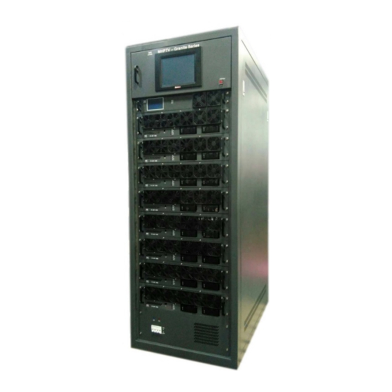
MHPTV TX Quick Start Guide 5 TX Interconnect Diagram Below is the front view of the Anywave 3-PA MHPTV Transmitter - which comes in single and dual exciter configurations. Photos of a single exciter system are shown below. The main subsystems (as seen from the front) include Exciter(s), one Controller... - Page 10 MHPTV TX Quick Start Guide From the rear view of the TX cabinet, several other main components can be seen which include an AC Distribution System, 3-way Splitter and Combiner, 2-port Directional coupler and Reject Load. Coupler Exciter Controller Combiner...
- Page 11 MHPTV TX Quick Start Guide The diagram below shows the overall system interconnect between the various modules in the 3-PA MHPTV system. MHPTV-QSG-DOC-V1.1, 12/05/2018 Page 11 of 37...
- Page 12 MHPTV TX Quick Start Guide The 3-PA MHPTV system Cabinet dimensions are shown below. Please note: the BPF (not shown) may be mounted on top or on the side of the TX cabinet. MHPTV-QSG-DOC-V1.1, 12/05/2018 Page 12 of 37...
-
Page 13: Rf System Connections
1. Mechanically mount BPF If you purchased an Anywave BPF, Anywave will design to install the BPF either on top of the TX cabinet or standing on the floor, according to the transmitter and the BPF’s dimensions, unless it is specified with order. - Page 14 MHPTV TX Quick Start Guide If the BPF is installed on the floor next to the TX cabinet, then put the BPF in standing position, and connect it with the transmitter with coax. Please note, if the LPF included in the system is not installed inside the cabinet, then it should be put between the transmitter and the BPF, as shown below.
-
Page 15: Ts Input Stream Connection
MHPTV TX Quick Start Guide Connect the After-filter Directional Coupler to the output of the BPF on one side and then to the 1 5/8 or 3 1/8 slip-on flange adapter on the other side (not shown in the photo above). This standard 1 5/8 or 3 1/8 EIA flanged output will then need to... - Page 16 MHPTV TX Quick Start Guide Please note: The above instructions apply to the 5X Exciter (which requires an ASI input signal) and is most likely the Exciter installed in your system. However, if you ordered the 9X Exciter (that can accept an ASI, SMPTE301M, or TSoIP (optional) TS input, the rear panel connections on your Exciter will look slightly different.
-
Page 17: Ac Mains Connections
MHPTV TX Quick Start Guide 8 AC Mains Connections Please review the safety WARNINGS on page 4 of this manual before proceeding with any electrical work. A licensed Electrician is required to properly and safely connect the AC mains power cable from your station's electrical panel to the terminal block located inside the TX AC Mains Distribution compartment in compliance with local electrical and building codes. - Page 18 MHPTV TX Quick Start Guide The MHPTV TX AC distribution compartment may be wired for 240VAC single- phase (3-wire, L1, L2, GND – for 1, 2, and 3-PA systems) or 208VAC three-phase (4- wire, L1, L2, L3, GND – for 1~8 Pa systems) power to be sourced from a proper breaker sized according to the charts below.
- Page 19 MHPTV TX Quick Start Guide Weight: 920 lbs. 15560W consumption 1794H x 1100D x 725W (mm) 5500(ATSC), 5PA 60A, 3pole breaker, gauge 6 wire 43.2A/phase-current draw Weight: 1060 lbs. 18670W consumption 2063H x 1100D x 725W (mm) 6600(ATSC), 6PA 70A, 3pole breaker, gauge 4 wire 51.9A/phase-current draw...
- Page 20 MHPTV TX Quick Start Guide 1-PA 240VAC, Single-Phase AC Distribution Wiring Properly connect the three wires to the terminal block as shown in the above diagram, taking care to notice which terminal is connected to the chassis Ground in your system.
- Page 21 MHPTV TX Quick Start Guide 1-PA 208VAC, Three-Phase AC Distribution Wiring Spare5 Spare4 Spare3 Spare2 Spare1 Exciter one Schneider iC65N D 50A Controller Load Amp1 3 4 5 6 7 8 9 10 11 12 13 14 15 16 17 18...
- Page 22 MHPTV TX Quick Start Guide 2-PA 240VAC, Single-Phase AC Distribution Wiring Spare5 Spare4 Spare3 Spare2 Spare1 Exciter one Controller Schneider iC65N D 50A Load Amp1 Amp2 1 2 3 4 5 6 7 8 9 10 11 12 13 14 15 16 17 18 19 20...
- Page 23 MHPTV TX Quick Start Guide 2-PA 208VAC, Three-Phase AC Distribution Wiring Spare5 Spare4 Spare3 Spare2 Spare1 Exciter one Controller Schneider iC65N D 50A Load Amp1 Amp2 1 2 3 4 5 6 7 8 9 10 11 12 13 14 15 16 17 18 19 20...
- Page 24 MHPTV TX Quick Start Guide 3-PA 208VAC, Three-Phase AC Distribution Wiring Spare5 Spare4 Spare3 Spare2 Spare1 Exciter one Controller Load Schneider iC65N D 50A Amp1 Amp2 Amp3 1 2 3 4 5 6 7 8 9 10 11 12 13 14 15 16 17 18 19 20 21 22...
- Page 25 MHPTV TX Quick Start Guide 4-PA 208VAC, Three-Phase AC Distribution Wiring Set-top fan Spare5 Spare4 Spare3 Spare2 Spare1 Exciter one Exciter two Controller Load Schneider Amp1 iC65N 4D 63A Amp2 Amp3 Amp4 1 2 3 4 5 6 7 8 9 10 11 12 13 14 15 16 17 18 19 20 21 22 23 24 25 26 27 28...
- Page 26 MHPTV TX Quick Start Guide 5-PA 208VAC, Three-Phase AC Distribution Wiring Set-top fan Spare5 Spare4 Spare3 Spare2 Spare1 Exciter one Exciter two Controller Load Amp1 Schneider Amp2 C120H C100 Amp3 Amp4 Amp5 1 2 3 4 5 6 7 8 9 10 11 12 13 14 15 16 17 18 19 20 21 22 23 24 25 26 27 28 29 30...
- Page 27 MHPTV TX Quick Start Guide 6-PA 208VAC, Three-Phase AC Distribution Wiring Set-top fan Spare5 Spare4 Spare3 Spare2 Spare1 Exciter one Exciter two Controller Load Amp1 Schneider Amp2 C120H C100 Amp3 Amp4 Amp5 Amp6 1 2 3 4 5 6 7 8 9 10 11 12 13 14 15 16 17 18 19 20 21 22 23 24 25 26 27 28 29 30 31 32...
- Page 28 MHPTV TX Quick Start Guide 8-PA 208VAC, Three-Phase AC Distribution Wiring Set-top fan Spare5 Spare4 Spare3 Spare2 Spare1 Exciter one Exciter two Controller Load Amp1 Amp2 Amp3 Amp4 Schneider Amp5 C120H C100 Amp6 Amp7 Amp8 1 2 3 4 5 6 7 8 9 10 11 12 13 14 15 16 17 18 19 20 21 22 23 24 25 26 27 28 29 30 31 32 33 34 35 36...
-
Page 29: Initial Turn On
(as outlined in sections 6 & 8) you are now ready to turn on the system. Please locate and have handy for reference a copy of your MPTV TX Factory Test Report as well as this MHPTV TX User Manual and Quick Start Guide, and Exciter User Manuals. - Page 30 MHPTV TX Quick Start Guide It takes a few seconds for the Controller to power up and display the HOME screen (shown below). Please note that the values will be different as the TX initially turns ON at a reduced power level.
- Page 31 MHPTV TX Quick Start Guide 3. You are now ready to bring the TX up to power. To accomplish this, slowly increase the drive level out of the Exciter by increasing the POWER setting in the Exciter RF submenu while watching the Sys FWD power increase accordingly on the Controller touchscreen.
- Page 32 MHPTV TX Quick Start Guide 5. Continue to slowly raise the FWD power until you reach the max power rating of the TX or your lower desired TPO. Check to be sure that the PA device currents do not exceed the full power operating currents as shown in your Factory Test Report.
- Page 33 MHPTV TX Quick Start Guide Linear and Non-Linear corrections were performed and optimized at the TX rated TPO in the factory and so the stored correction coefficients should produce good results if you are operating at or close to the TX max output power.
- Page 34 MHPTV TX Quick Start Guide Set Target AGC Power to desired TPO Press AGC button to turn AGC ON (will illuminate Green) 8. Press the HOME button to return to the HOME screen to monitor FWD power With the AGC engaged, the FWD power metering may vary up to +/- 5%, so for a 1500W TPO, meter variations from 1425W to 1575W may be experienced.
- Page 35 MHPTV TX Quick Start Guide 10. Your TX should now be up and running properly into your load or on-air antenna. Continue to monitor system parameters as you allow the transmitter to warm up to temperature and stabilize at full output power for another 30 minutes.
- Page 36 CONTROL button setting and set the Exciter to REMOTE mode under the SYSTEM submenu by setting CTL=RMT. This will enable remote monitoring and control of the TX via its built-in web interfaces (refer to the MHPTV TX and Exciter user manuals for details).
- Page 37 MHPTV TX Quick Start Guide Anywave Communication Technologies Inc. 300 Knightsbridge Parkway, Suite 150, Lincolnshire, IL 60069 Tel: (847) 415-2258 Fax: (847) 415-2112 Email: sales_us@anywavecom.com http://www.anywavecom.com/en/ MHPTV-QSG-DOC-V1.1, 12/05/2018 Page 37 of 37...
Need help?
Do you have a question about the MHPTV and is the answer not in the manual?
Questions and answers