Table of Contents
Advertisement
Quick Links
Advertisement
Table of Contents

Related Manuals for Anywave ATSC 1.5KW


Summary of Contents for Anywave ATSC 1.5KW
- Page 1 ANYWAVE ATSC 1.5KW DTV Transmitter User Manual Version 1.4 September 12, 2014...
- Page 2 ATSC 1.5KW DTV TX User Manual Copyright Notice Copyright © Anywave Communication Technologies, Inc. 2014, All rights reserved. No part of this publication may be reproduced, translated, transcribed, stored in a retrieval system, or transmitted into any form or by any means, without the express written permission of Anywave Communication Technologies, Inc.
- Page 3 Returns and Exchanges Written approval and a Return Authorization Number (RAN) are required from Anywave for all equipment returns. Please direct all return inquiries to the Anywave Service Department at support_us@anywavecom.com, providing the Sales Order number and Serial Number(s) of the equipment.
- Page 4 The installation, operation, maintenance and service of this equipment involves risks both to personnel and equipment, and must ONLY be performed by qualified personnel exercising due care. Anywave Communication Technologies, Inc. shall not be responsible for injury or damage resulting from improper handling or from the use of improperly trained or inexperienced personnel performing such tasks.
-
Page 5: Table Of Contents
ATSC 1.5KW DTV TX User Manual Contents 1 Introduction .................... 7 2 TX System Overview ................8 3 TX Specifications ................. 10 4 Control Unit ..................11 5 Digital Exciter ..................14 6 Power Amplifier – 600W ..............16 7 TX System Interconnect Diagram ............19 8 Theory of Operation ................ - Page 6 ATSC 1.5KW DTV TX User Manual 13.5 LOG SCREEN ......................61 13.6 CONTROL SCREEN ....................61 13.7 HELP SCREEN ......................62 13.8 EMERGENCY MODE ....................63 14 Remote (Web) User Interface ............64 ACT-1500-USR-DOC-V1.4 09/12/2014 Page 6 of 76...
-
Page 7: Introduction
ATSC 1.5KW DTV TX User Manual 1 Introduction This User Manual contains operational instructions for the Anywave 1.5KW DTV Transmitter. Please note that trained and qualified personnel are required to operate install, maintain, and service this transmission equipment. ACT-1500-USR-DOC-V1.4 09/12/2014... -
Page 8: Tx System Overview
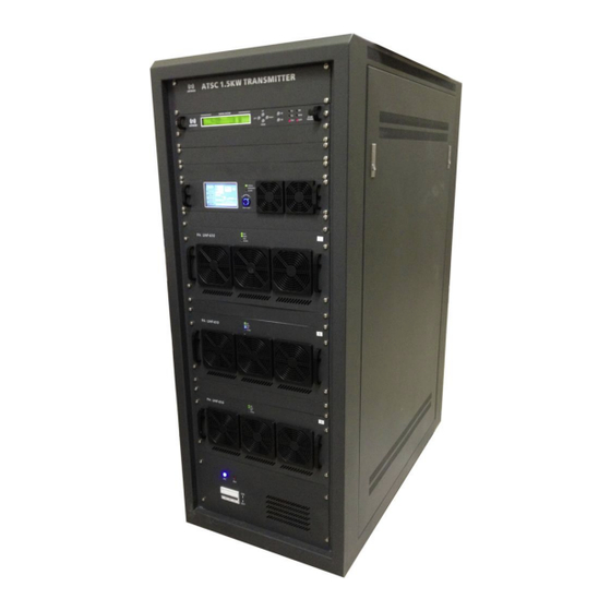
ATSC 1.5KW DTV TX User Manual 2 TX System Overview The Anywave ATSC 1.5KW DTV Transmitter comes in single and dual exciter configurations. Photos of a single exciter system are shown below. The main subsystems (as seen from the front) include the Exciter, Controller unit (with a touchscreen LCD, and built-in preamp), three 600W power amplifiers, an AC Mains Breaker, and a channel mask Band Pass Filter (BPF) - optional. - Page 9 ATSC 1.5KW DTV TX User Manual From the rear view of the TX cabinet, several other main components can be seen which include a 3-way Splitter, 2-port Directional Coupler, 3-Way Combiner, Reject Loads, and AC Distribution System. 2-port Coupler 3-Way Combiner...
-
Page 10: Tx Specifications
ATSC 1.5KW DTV TX User Manual 3 TX Specifications RF Output Connector: 1 5/8”, 50 Ω Frequency: 470~860 MHz, in steps of 1 Hz Rated Power: 1.5kW (rms) Level Stability: < ±0.2 dB MER: >... -
Page 11: Control Unit
ATSC 1.5KW DTV TX User Manual 4 Control Unit The TX Control Unit consists of a pre-amp (1xBLF571 driving 2xBLF881 devices) and a powerful control system. It receives the RF input(s) from the exciter(s), performs the pre- amplification, and finally sends a preamplified output to the 4-way splitter which feeds the 4 PA modules. - Page 12 ATSC 1.5KW DTV TX User Manual Rear Panel The rear panel of Control Unit is shown below: RF_MON: Loop out of RF_OUT1/RF_OUT2 for monitoring RF_IN_A/RF_IN_B Connector: 50 Ω Impedance: Note: To receive the RF_OUT signal from Exciter_A / Exciter_B ...
- Page 13 ATSC 1.5KW DTV TX User Manual LAN: 10M/100M Ethernet port for web-based remote control (ipaddress: 192.168.1.210) AC INPUT/FUSE: 100-240 VAC Power Switch: ON/OFF ACT-1500-USR-DOC-V1.4 09/12/2014 Page 13 of 76...
-
Page 14: Digital Exciter
ATSC 1.5KW DTV TX User Manual 5 Digital Exciter Front Panel LCD: 40×2 LCD with power saving backlight 6 Buttons : Left, Right, Up, Down, OK, ESC 6 LEDs: When in Exciter mode: LED_TS1: Green light on indicates TS1 is selected and the input TS signal is OK... - Page 15 ATSC 1.5KW DTV TX User Manual Rear Panel RF_IN_A: Feedback signal, sampled after the band-pass filter (-5 to -15dBm) RF_IN_B: Feedback signal, sampled before the band-pass filter (-5 to -15dBm) AGC_IN: Feedback DC voltage for AGC control (0-5VDC) RF_MON: Loop out of RF_OUT for monitoring (-25 dB below RF_OUT)
-
Page 16: Power Amplifier - 600W
ATSC 1.5KW DTV TX User Manual 6 Power Amplifier – 600W This TX is fitted with three UHF-610 PA modules to produce a total 1500W of output power after the BPF. Each module consists of two 2 pallets (a total of 4 BLF888A devices). - Page 17 ATSC 1.5KW DTV TX User Manual Red light will be off if there is no alarm Note: The front fan covers can be removed to clean the air intake path. No screw driver is needed, and no disassembly of the PA is required.
- Page 18 ATSC 1.5KW DTV TX User Manual AC220V input: To be connected with Power Supply System. Power Switch: ON/OFF Note: The back fan covers can also be removed to clean the air intake path. No screw driver is needed, and no disassembly of the PA is required.
-
Page 19: Tx System Interconnect Diagram
ATSC 1.5KW DTV TX User Manual 7 TX System Interconnect Diagram The diagram below shows the overall system interconnect between the various modules. ACT-1500-USR-DOC-V1.4 09/12/2014 Page 19 of 76... -
Page 20: Theory Of Operation
ATSC 1.5KW DTV TX User Manual 8 Theory of Operation The ATSC 1500W DTV transmitter is conceptually simple to understand and easy to operate. The Transmitter can be ordered wired for either 220VAC single-phase 60A or 208VAC 3- phase 50A AC Mains service. An AC Mains Distribution compartment is located in the back rear floor of the TX. -
Page 21: Quick Start Guide
ATSC 1.5KW DTV TX User Manual from the System Reject Load, enabling it to control the variable fan speed on the load. The Control module is in constant communication with the Exciter and PA modules via an RS-485 serial bus. Each module has a unique ID on the bus, and the Control module is continually talking with the Exciter and PA modules to provide monitoring and control capabilities via its front panel touchscreen and built-in web user interfaces. -
Page 22: Rf System Connections
ATSC 1.5KW DTV TX User Manual 10 RF System Connections If you purchased an Anywave BPF, it is designed to be installed and mounted on top of the 1.5KW TX cabinet (as shown below). Four metal stand-offs “feet” with mounting hardware are supplied with the BPF to allow it to be fastened and secured to four holes located in the top panel of the cabinet. - Page 23 ATSC 1.5KW DTV TX User Manual (Please note: If your Antenna feed is other than 1 5/8 EIA flanged (as shown on left), then you will need to provide whatever adapter hardware is necessary to facilitate this connection to your Antenna feed).
-
Page 24: Ac Mains Connections
ATSC 1.5KW DTV TX User Manual 11 AC Mains Connections Please review the safety WARNINGS on page 4 of this manual before proceeding with any electrical work. A licensed Electrician is required to properly and safely connect the 208V or 220V... - Page 25 ATSC 1.5KW DTV TX User Manual 208VAC 3-phase Electrical Requirements The 1.5KW ATSC Transmitter cabinet may be wired for 208VAC three-phase power to be sourced from a 40A 3-pole breaker. A 4-wire gauge 8 cable is recommended to make the connection between the TX AC Mains Distribution terminal block and the 3-pole 40A breaker in the facility electrical panel.
- Page 26 ATSC 1.5KW DTV TX User Manual 220VAC Single-phase Electrical Requirements The 1.5KW ATSC Transmitter cabinet may be wired for 220VAC single-phase power to be sourced from a 60A 2-pole breaker. A 3-wire gauge 4 cable is recommended to make the connection between the TX AC Mains Distribution terminal block and the 2-pole 60A breaker in the facility electrical panel.
-
Page 27: Operational Basics
ATSC 1.5KW DTV TX User Manual 12 Operational Basics 12.1 TX ON/OFF Local Control: To turn the TX On/Off, please use the TX On/Off button located on the HOME screen of the Control module. The Button will light Green when the TX is ON and RED when the TX is off. -
Page 28: Raise/Lower Power
ATSC 1.5KW DTV TX User Manual 12.2 RAISE/LOWER POWER Local Control: To raise or lower the TX system forward power, please adjust the target AGC power setting on the Controller AGC screen. Monitor the change in power via the Home screen FWD Power meter (which may take up to 60 seconds). -
Page 29: Running Corrections
ATSC 1.5KW DTV TX User Manual 12.3 RUNNING CORRECTIONS Local Control: This section guides you through the process of running Linear and Nonliner Precorrection (You may also reference the Exciter User Manual for additional details and instructions on running corrections). If you are operating at reduced power you may wish to rerun corrections to achieve better RF performance. - Page 30 ATSC 1.5KW DTV TX User Manual 3. Before running corrections, it is important to verify proper feedback signal levels. There are two feedback signal samples used to compute corrections. “RF In A” (After BPF) is used to calculate Linear correction coefficients while “RF IN B”...
- Page 31 ATSC 1.5KW DTV TX User Manual 7. Check the SNR and Shoulder (LIMD and UIMD) RF performance on the front panel screen of the exciter or by pressing the Exciter Icon on the Controller HOME screen. (Change the value of CFR or rerun correction if necessary to obtain optimal performance).
- Page 32 ATSC 1.5KW DTV TX User Manual Set Target AGC Power to full 1500W or desired TPO Press AGC button to turn AGC ON (will illuminate Green) 10. Press the HOME button to return to the HOME screen to monitor FWD power as it slowly reduces from 1.1 x TPO to the AGC target power...
- Page 33 ATSC 1.5KW DTV TX User Manual 11. On the Exciter, navigate to the CAL setting under the AD3 Advanced submenu and select CAL then press OK to calibrate the FWD PWR meter on the Exciter front panel to ~ 100%.
-
Page 34: Calibrate Exciter Fwd Power Meter
ATSC 1.5KW DTV TX User Manual 12.4 CALIBRATE EXCITER FWD POWER METER On the Exciter, navigate to the CAL setting under the AD3 Advanced submenu and select CAL then press OK to calibrate the FWD PWR meter on the Exciter front panel to ~ 100%. -
Page 35: Calibrate Tx System Power Meters
ATSC 1.5KW DTV TX User Manual 12.5 CALIBRATE TX SYSTEM POWER METERS Local Control: There are three TX system power meters located on the Controller HOME screen, Forward (FWD), Reflected (REFL), and Reject Load (REJT). These power meters were calibrated at the factory to provide accurate power readings when testing the TX at full output power (1500W after the BPF). - Page 36 ATSC 1.5KW DTV TX User Manual Normal operation for the 1.5KW TX is to run with the Transmitter AGC enabled to compensate for slight variations in output power due to changes in temperature, AC mains, etc. It is not recommended to perform power meter calibration with AGC enabled.
- Page 37 ATSC 1.5KW DTV TX User Manual 3. Disconnect the FWD IN sample from the rear panel of the Controller and connect this to your power meter. This sample comes from the TX output directional coupler and has a coupling value of 50dB (offset for your power meter).
- Page 38 ATSC 1.5KW DTV TX User Manual 6. Navigate to the TX meter Calibration screen on the Controller by pressing the CONFIG button and then selecting AmpCF (Amplifier Configuration) The AmpCF screen is used to configure advanced settings of the TX System and PAs, and is locked with a password.
- Page 39 ATSC 1.5KW DTV TX User Manual With the password properly entered, the AmpCf configuration screen will appear, as shown below. Press the ComCF button. The ComCF screen is used to configure the TX maximum operating thresholds to engage safety and protective power reduction and shutdown mechanisms. Press the NextPage button to reach the FWD, REFL, and REJT power calibration screen below.
- Page 40 ATSC 1.5KW DTV TX User Manual 7. Press the word FwdPara to slightly adjust this value up or down (in small increments 0.1, 0.2, etc.) until the FWD power meter reading on the Controller HOME screen (also available via the Controller Web interface: RJ-45 LAN default IPaddress 192.168.1.210) agrees with the value of...
- Page 41 ATSC 1.5KW DTV TX User Manual 9. Repeat steps 3 through 7 above, this time removing, measuring, and returning the RJCT IN sample to calibrate the Reject Load 1 system power meter by adjusting the value of Rejt1 below. Calibration for...
- Page 42 ATSC 1.5KW DTV TX User Manual 11. With your TX operating at your desired output power and with accurately calibrated system power metering, the next step is to set up and re-engage the TX AGC. To accomplish this, slowly increase the value of POWER in the Exciter RF submenu to raise the output power of the system to 1.1 x...
- Page 43 ATSC 1.5KW DTV TX User Manual 13. Press the HOME button to return to the HOME screen to monitor FWD power as it slowly reduces from 1.1 x TPO to the AGC target power (desired TPO) level over the next minute or so. With the AGC engaged, the FWD power metering may vary up to +/- 5%, so for a 1500W TX, meter variations from 1425W to 1575W may be experienced.
-
Page 44: Local (Touch Screen) User Interface
ATSC 1.5KW DTV TX User Manual 13 Local (Touch Screen) User Interface 13.1 HOME SCREEN Turn on the power supply and the TX enters the initialization process, and after 5 seconds, the TX enters the home screen (as shown below). -
Page 45: A/B Exciter Icon Screen
ATSC 1.5KW DTV TX User Manual VSWR: Voltage Standing Wave Ratio REJT: This is the system Reject Load Power Meter, derived from the REJT Load feedback sample. Displayed in units of “W” and cannot be changed. Status Bar: During normal operation, the default status is “RUNNING OK”. If there is any alarm, the alarm will show up in the Status Bar of each screen. - Page 46 ATSC 1.5KW DTV TX User Manual Manual Exciter Switchover: Exciter A is the default on-air exciter. The on-air exciter’s status will be “GREEN”, as shown in the screen above, indicating that Exciter B is the current on-air exciter. Pressing the “Exciter A” or “Exciter B” button on this screen will cause a manual switch between exciters, that is if the Controller is “linked”...
- Page 47 ATSC 1.5KW DTV TX User Manual If the manual switching is successful, a window will pop up indicating “Change succeed!”, as shown below. If the manual switching is not successful, a window will pop up indicating “Change failed!”, as shown below.
- Page 48 ATSC 1.5KW DTV TX User Manual Pressing the Exciter A or Exciter B button will bring up a window displaying the Exciter Channel Frequency and well as the TX System SNR and Upper and Lower Shoulder metrics. Please note: only the on-air exciter has valid readings.
-
Page 49: Amplifier Icon Screen
ATSC 1.5KW DTV TX User Manual 13.3 AMPLIFIER ICON SCREEN Amplifier Status Screens: As mentioned above, pressing the “Amplifier” icon on the Home page, will navigate to the Amplifier Status Screens. Title Bar: includes “PreAmp”, “Amp1”, “Amp2”, (“Amp3 and more buttons are for higher power transmittes in the MPTV product line). - Page 50 ATSC 1.5KW DTV TX User Manual Amp1/Amp2 Status Screen ACT-1500-USR-DOC-V1.4 09/12/2014 Page 50 of 76...
- Page 51 ATSC 1.5KW DTV TX User Manual Fwd: Forward Power reading of the current amplifier Refl: Reflected Power reading of the current amplifier Fan1~Fan2: Fans’ RPM of the current amplifier Tmp: Temperature of the current amplifier ...
-
Page 52: Config Screen
ATSC 1.5KW DTV TX User Manual 13.4 CONFIG SCREEN Touching the Config button on Title Bar of the Home Screen, will navigate to the Config Screen, as shown below. The Config Screen has seven functional sections on the right. Press any of these buttons to navigate to that config screen. The Network screen is used to configure all the TX networking parameters including IP, Mask, and Gateway. - Page 53 ATSC 1.5KW DTV TX User Manual Network Screen: The User can check and set all the Contoller network information in this screen. Re-Defualt: Reset Default settings - This button is used to set all the network settings to the default values, as show below: 192.168.1.210...
- Page 54 ATSC 1.5KW DTV TX User Manual Time Screen: This screen is used to check and adjust the current time settings. It’s similar to the Network Settings. ACT-1500-USR-DOC-V1.4 09/12/2014 Page 54 of 76...
- Page 55 ATSC 1.5KW DTV TX User Manual AGC Screen: This screen is used to set the AGC Reference output power of the TX and to turn the Controller AGC ON/OFF. Press the AGC button to turn AGC ON (button will turn green).
- Page 56 ATSC 1.5KW DTV TX User Manual With the password properly entered, the AmpCf configuration screen will appear, as shown below. ComCf Screen: This screen is used to configure the TX maximum operating thresholds to engage safety and protective power reduction and shutdown mechanisms.
- Page 57 ATSC 1.5KW DTV TX User Manual FwdMax: Max TX Forward Power fault threshold ReflMax: Max TX Reverse Power fault threshold Rejt1-4Max: Max TX Reject Load fault threshold VSWRMax: Max TX VSWR fault threshold (Note: Press the word FwdMax, ReflMax, etc. to see a pop-up screen to modify these settings.
- Page 58 ATSC 1.5KW DTV TX User Manual PreAmpCf Screen: This screen is used to configure the Preamp maimum operating thresholds to engage safety and protective power reduction and shutdown mechanisms. (Please note that AdjPara and InPara are always set to 0.0) PosID Screen: This screen is used to configure and/or test the RS-485 communications between the Control module and each of the PA modules.
- Page 59 ATSC 1.5KW DTV TX User Manual Amp1Cf/Amp2Cf / Amp3Cf Screens: These screens are used to configure the Maximum PA operating thresholds to engage safety and protective power reduction and shutdown mechanisms. Exciter Screen: This screen is used to configure the TX for single or dual exciters.
- Page 60 ATSC 1.5KW DTV TX User Manual Bootset Screen: This screen is used to configure the number of attempts that the TX takes to successfully reboot on a shutdown condition, after which it gives up and remains off- air. ClrALM: This is the Clear Alarm screen which is used to clear all alarms and recover the rated power (Note: ClrALM cannot be used in REMOTE mode) In LOCAL MODE, press the ClrALM button and a window pops out as below.
-
Page 61: Log Screen
ATSC 1.5KW DTV TX User Manual 13.5 LOG SCREEN Pressing the Log button on Title Bar in the Home Screen will navigate to the Log Screen, as shown below. There are two pages of current alarm information as well as history alarms. -
Page 62: Help Screen
ATSC 1.5KW DTV TX User Manual 13.7 HELP SCREEN ACT-1500-USR-DOC-V1.4 09/12/2014 Page 62 of 76... -
Page 63: Emergency Mode
ATSC 1.5KW DTV TX User Manual 13.8 EMERGENCY MODE When turning the NORMAL/EMERGENCY switch 90°clockwise from NORMAL (N) to EMERGENCY (E) mode, the touch screen is shown as below. Note: If the EMERGENCY mode is turned on by mistake, after the transmitter is switched back to NORMAL mode, touching the “HOME”... -
Page 64: Remote (Web) User Interface
ATSC 1.5KW DTV TX User Manual 14 Remote (Web) User Interface The TX Control module provides a built-in web interface that enables remote monitoring and control of the TX. This Control Module interface may be used for a variety of things, including turning the TX On/Off, manually switching between exciters (in a DD configuration), monitoring the voltages and currents of the PAs, etc. - Page 65 ATSC 1.5KW DTV TX User Manual There are two tiers of web interface available. The first “guest” tier is limited in monitoring and control, allowing users to access only certain information. The guest account is accessed with a user name and password of "guest" and "guest" (case sensitive). The second “admin” tier provides full status and control of the Controller and is accessed with a username and password of "anywavecom"...
- Page 66 ATSC 1.5KW DTV TX User Manual ACT-1500-USR-DOC-V1.4 09/12/2014 Page 66 of 76...
- Page 67 ATSC 1.5KW DTV TX User Manual ACT-1500-USR-DOC-V1.4 09/12/2014 Page 67 of 76...
- Page 68 ATSC 1.5KW DTV TX User Manual ACT-1500-USR-DOC-V1.4 09/12/2014 Page 68 of 76...
- Page 69 ATSC 1.5KW DTV TX User Manual ACT-1500-USR-DOC-V1.4 09/12/2014 Page 69 of 76...
- Page 70 ATSC 1.5KW DTV TX User Manual ACT-1500-USR-DOC-V1.4 09/12/2014 Page 70 of 76...
- Page 71 ATSC 1.5KW DTV TX User Manual ACT-1500-USR-DOC-V1.4 09/12/2014 Page 71 of 76...
- Page 72 ATSC 1.5KW DTV TX User Manual ACT-1500-USR-DOC-V1.4 09/12/2014 Page 72 of 76...
- Page 73 ATSC 1.5KW DTV TX User Manual ACT-1500-USR-DOC-V1.4 09/12/2014 Page 73 of 76...
- Page 74 ATSC 1.5KW DTV TX User Manual ACT-1500-USR-DOC-V1.4 09/12/2014 Page 74 of 76...
- Page 75 ATSC 1.5KW DTV TX User Manual ACT-1500-USR-DOC-V1.4 09/12/2014 Page 75 of 76...
- Page 76 ATSC 1.5KW DTV TX User Manual Anywave Communication Technologies Inc. 300 Knightsbridge Parkway, Suite 150, Lincolnshire, IL 60069 Tel: (847) 415-2258 Fax: (847) 415-2112 Email: sales_us@anywavecom.com http://www.anywavecom.com/en/ ACT-1500-USR-DOC-V1.4 09/12/2014 Page 76 of 76...
Need help?
Do you have a question about the ATSC 1.5KW and is the answer not in the manual?
Questions and answers