Advertisement
Quick Links
Advertisement

Related Manuals for Anywave PA-140W


Summary of Contents for Anywave PA-140W
- Page 1 ANYWAVE PA-140W User Manual Version 1.4 – September 12, 2014...
- Page 2 This equipment complies with relevant portions of Parts 2, 73, & 74 of the FCC rules governing LPTV operation. Disclaimer Information provided by Anywave Communication Technologies is believed to be accurate and complete; however, no liability can be assumed for its use. The manufacturer makes no representations or warranties, either expressed or implied, by or with respect to anything in this manual, and shall not be liable for any implied warranties of fitness for a particular purpose or for any indirect, special, or consequential damages.
- Page 3 Returns and Exchanges Written approval and a Return Authorization Number (RAN) are required from Anywave for all equipment returns. Please direct all return inquiries to the Anywave Service Department at support_us@anywavecom.com, providing the Sales Order number and Serial Number(s) of the equipment.
- Page 4 The installation, operation, maintenance and service of this equipment involves risks both to personnel and equipment, and must ONLY be performed by qualified personnel exercising due care. Anywave Communication Technologies, Inc. shall not be responsible for injury or damage resulting from improper handling or from the use of improperly trained or inexperienced personnel performing such tasks.
-
Page 5: Table Of Contents
PA-140W User Manual Contents 1 Product Appearance ..................6 1.1 Front Panel ..................... 6 1.2 Back Panel ..................... 7 2 Specifications ....................8 3 Control Interface ....................9 3.1 Local Control Interface .................. 9 3.2 Serial Port Interface ..................9 3.3 Web Interface .................... -
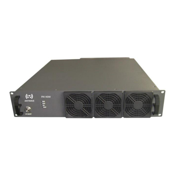
Page 6: Product Appearance
PA-140W User Manual 1 Product Appearance 1.1 Front Panel RF Button Press the RF button to turn the RF signal ON (inside blue light will light up). Press the RF button again to turn the RF signal OFF (inside blue light will be off). -
Page 7: Back Panel
PA-140W User Manual 1.2 Back Panel RF_IN Connector: 50 Ω Impedance: Rated Power: +1.76 dBm ± 1 dB Note: If input power from RF_IN is lower than rated input value, the output power will be lower than rated output power accordingly. -
Page 8: Specifications
PA-140W User Manual RJ45 Connector: 10M/100M Ethernet Note: For customers’ remote control to the PA. Connector: Input Level: -20 to +10 dBm Note: External Coupler Forward sample for PA_FWD Power Meter. ... -
Page 9: Control Interface
PA-140W User Manual 3 Control Interface 3.1 Local Control Interface Local control and monitoring of the PA unit is accomplished via the ACT-5X Exciter front panel user interface. Use a standard serial cable to connect the PA D9 RS232-A port to the ACT-5X Exciter D9 REMOTE (RS232) port. -
Page 10: Web Interface
PA-140W User Manual 3.3 Web Interface Enter the IP address of the PA (the default value is 192.168.1.210) in a web browser's address bar to cause a login window to pop up. There are two tiers of web interface available. The first “guest” tier is limited in monitoring and control, allowing users to retrieve information such as PA status, network configuration, and alarms. - Page 11 PA-140W User Manual Admin Web Page ACT-140PA-USR-DOC-V1.4, 09/12/2014 Page 11 of 13...
- Page 12 PA-140W User Manual Note: 1) To refresh the status of the PA unit, manually click the “Query” button(s) on the page, or set up the “AUTO-REFRESH-CYCLE” for the auto periodic refreshing of status. 2) Configuration settings including “POWER_DEGREE”, “EXCITER_TYPE”, internet access settings and “REFRESH-CYCLK”...
- Page 13 PA-140W User Manual Anywave Communication Technologies Inc. 300 Knightsbridge Parkway, Suite 150, Lincolnshire, IL 60069 Tel: (847) 415-2258 Fax: (847) 415-2112 Email: sales_us@anywavecom.com http://www.anywavecom.com/en/ ACT-140PA-USR-DOC-V1.4, 09/12/2014 Page 13 of 13...
Need help?
Do you have a question about the PA-140W and is the answer not in the manual?
Questions and answers