
Related Manuals for Anywave PA-U-2200-D-FB Marble


Summary of Contents for Anywave PA-U-2200-D-FB Marble
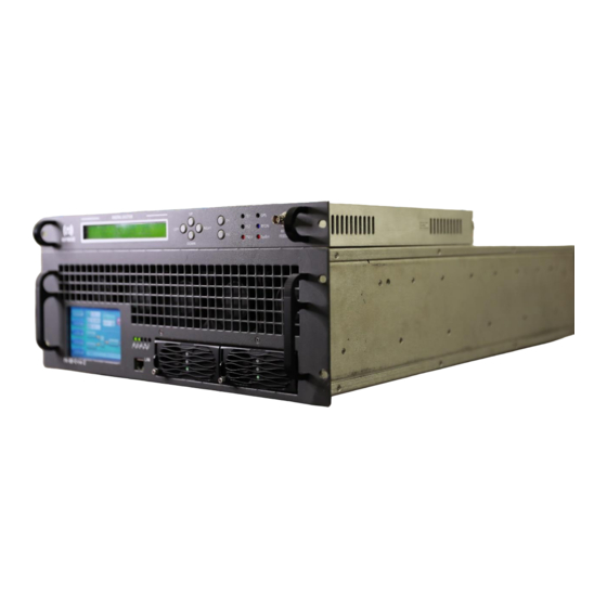
- Page 1 ANYWAVE PA-U-2200-D-FB Marble DTV Transmitter Quick Start Guide Version 2.0 – May 19, 2022...
- Page 2 Marble 8Device Quick Start Guide Copyright Notice Copyright © Anywave Communication Technologies, Inc. 2021, All rights reserved. No part of this publication may be reproduced, translated, transcribed, stored in a retrieval system, or transmitted into any form or by any means, without the express written permission of Anywave Communication Technologies, Inc.
- Page 3 Returns and Exchanges Written approval and a Return Authorization Number (RAN) are required from Anywave for all equipment returns. Please direct all return inquiries to the Anywave Service Department at support_us@anywavecom.com, providing the Sales Order number and Serial Number(s) of the equipment.
- Page 4 The installation, operation, maintenance, and service of this equipment involves risks both to personnel and equipment, and must ONLY be performed by qualified personnel exercising due care. Anywave Communication Technologies, Inc. shall not be responsible for injury or damage resulting from improper handling or the use of improperly trained or inexperienced personnel performing such tasks.
- Page 5 Marble 8Device Quick Start Guide Contents Introduction ..................6 TX System Overview ............... 6 TX System Interconnect ..............7 Initial Turn On .................. 8 Mable 8Device Quick Start Guide, 5/19/2022 Page 5 of 18...
-
Page 6: Introduction
2 TX System Overview Final assembly and test of each transmitter are performed at the Anywave factory. The Exciter is set up on the desired channel frequency and the TX is tested with the complete RF system (if purchased) at full power into a load. All TX operating parameters are optimized and the Transmitter Forward and Reflected power meters are properly calibrated. -
Page 7: Tx System Interconnect
Marble 8Device Quick Start Guide 3 TX System Interconnect The Anywave PA-U-2200-D-FB Marble DTV Transmitter consists of an Exciter, a PA-U-2200-D-FB (with built-in Controller), a 7/16 DIN Directional Coupler, a 7/16 DIN 90 degree elbow, a 7/16-to-1-5/8 adapter, a 1-5/8 LPF, a 1-5/8 90 degree elbow, a... -
Page 8: Initial Turn On
Marble 8Device Quick Start Guide Below is an example photo showing the system connections. (Please note: this photo is illustrative only and your system connections may differ slightly. Please refer to the system diagram above for the specific system interconnection for your 2KW system). 4 Initial Turn On Please locate and have handy for reference a copy of your Factory Test Report as well as the Quick Start Guide, and PA and Exciter User Manuals. - Page 9 Marble 8Device Quick Start Guide Check the Exciter drive level is set to -25dBm by navigating to the Exciter RF submenu (from above, press the ESC button then enter the RF submenu). (Please refer to your Exciter User Manual for help with the detailed operation of the Exciter).
- Page 10 Marble 8Device Quick Start Guide connected to the rear of the Exciter. With this cable properly connected and the PA FREQ-TYPE set to AUTO mode (as shown in the web page screenshot below), the PA should automatically detect the Exciter output channel frequency, display this FREQ on its main Status webpage, and adjust its internal meter calibrations accordingly (as the PA gain varies slightly between channels).
- Page 11 Marble 8Device Quick Start Guide If the PA FREQ does not match the Exciter TX FREQ, please be sure that the serial cable is properly connected don each side. You can alternatively bypass the PA AUTO detection of the Exciter channel FREQ by changing the PA FREQ-TYPE from AUTO to MANUAL –...
- Page 12 Marble 8Device Quick Start Guide 8) You are now ready to slowly bring the TX power up. To accomplish this, slowly increase the drive level out of the Exciter by increasing the POWER setting in the Exciter RF submenu while watching the FWD-POW power increase accordingly on the PA’s touchscreen, and its Web Interface.
- Page 13 Marble 8Device Quick Start Guide Monitor FWD SYS POWER Monitor FWD SYS POWER 9) Continue to slowly raise the FWD power until you reach the rated power (2200W before BPF in ATSC), or your desired TPO. Be careful to make small increases in the value of POWER as you approach the desired output level.
- Page 14 Marble 8Device Quick Start Guide 10) Check the SNR and Shoulder (LIMD and UIMD) RF performance of your system on the Exciter hi-level status screen, as well as the exciter’s pages on the PA’s touchscreen as shown below. Linear and Non-Linear corrections were already performed and optimized at a TPO of 2200W (before BPF, in ATSC 1.0) in the factory and so the stored correction coefficients should produce good results.
- Page 15 Marble 8Device Quick Start Guide Your TX should now be up and running properly into your load or on-air antenna. Continue to monitor system parameters as you allow the transmitter to operate and stabilize at full output power for another 30 minutes. 15) Navigate to the CAL setting under the AD3 Advanced submenu and select CAL then press OK to calibrate the FWD PWR meter on the Exciter front panel to 100%.
- Page 16 Marble 8Device Quick Start Guide connection at 192.168.1.143 – you can change the exciter IP address by navigating to the CONFIG submenu (simultaneously press Left and Right buttons) and changing the value of IP (please reference your Exciter User Manual for details). 18) If using the Exciter Built-in remote web interface for remote control, please be sure to set the Exciter to REMOTE mode (set CTL to RMT) before leaving the transmitter site.
- Page 17 Marble 8Device Quick Start Guide Mable 8Device Quick Start Guide, 5/19/2022 Page 17 of 18...
- Page 18 Marble 8Device Quick Start Guide Anywave Communication Technologies Email: sales_us@anywavecom.com Phone: +1 (847) 415 2258 Fax: +1 (847) 415 2112 Address: 100 N Fairway Drive, Suite 128 Vernon Hills, IL 60061 Website: www.anywavecom.net Mable 8Device Quick Start Guide, 5/19/2022 Page 18 of 18...
Need help?
Do you have a question about the PA-U-2200-D-FB Marble and is the answer not in the manual?
Questions and answers