
Related Manuals for Anywave ATSC 140W


Summary of Contents for Anywave ATSC 140W
- Page 1 ANYWAVE ATSC 140W DTV Transmitter Quick Start Guide Version 1.3 – September 29, 2014...
- Page 2 ATSC 140W TX Quick Start Guide Copyright Notice Copyright © Anywave Communication Technologies, Inc. 2014, All rights reserved. No part of this publication may be reproduced, translated, transcribed, stored in a retrieval system, or transmitted into any form or by any means, without the express written permission of Anywave Communication Technologies, Inc.
- Page 3 Returns and Exchanges Written approval and a Return Authorization Number (RAN) are required from Anywave for all equipment returns. Please direct all return inquiries to the Anywave Service Department at support_us@anywavecom.com, providing the Sales Order number and Serial Number(s) of the equipment.
- Page 4 The installation, operation, maintenance and service of this equipment involves risks both to personnel and equipment, and must ONLY be performed by qualified personnel exercising due care. Anywave Communication Technologies, Inc. shall not be responsible for injury or damage resulting from improper handling or from the use of improperly trained or inexperienced personnel performing such tasks.
-
Page 5: Table Of Contents
ATSC 140W TX Quick Start Guide Contents Introduction ..................6 Organization of Manual ..............6 TX System Overview ............... 7 TX System Interconnect ..............8 Initial Turn On .................. 9 ACT-140-QSG-DOC-V1.3, 09/29/2014 Page 5 of 13... -
Page 6: Introduction
1 Introduction This Quick Start Guide contains instructions to safely setup and turn on the Anywave 140W DTV Transmitter. Please note that trained and qualified personnel are required to install, maintain, and service this transmission equipment. 2 Organization of Manual This Manual is broken up into several sections. -
Page 7: Tx System Overview
ATSC 140W TX Quick Start Guide 3 TX System Overview Final assembly and test of each transmitter is performed at the Anywave factory. The Exciter is setup on the desired channel frequency and the TX is tested with the complete RF system (if purchased) at full power into a load. All TX operating parameters are optimized and the Transmitter Forward and Reflected power meters are properly calibrated. -
Page 8: Tx System Interconnect
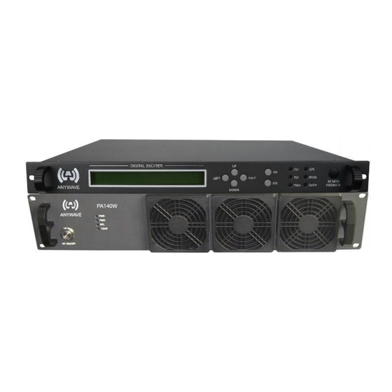
ATSC 140W TX Quick Start Guide 4 TX System Interconnect The Anywave ATSC 140W DTV Transmitter consists of an Exciter, 140W PA, Directional Coupler (50dB for PA FWD and REF samples), and a BPF (optional) with two additional single port couplers for Exciter feedback samples (optional). The diagram below shows the overall system interconnect between the system components. -
Page 9: Initial Turn On
ATSC 140W TX Quick Start Guide 5 Initial Turn On Please locate and have handy for reference a copy of your 140W TX Factory Test Report as well as the 140W TX Quick Start Guide, and 140W PA and Exciter User Manuals. - Page 10 ATSC 140W TX Quick Start Guide and verify that the voltages (Vol_9 and Vol_50) and current (Cur1_50) are showing real values and not all 0s. 6. You are now ready to bring the TX up to power. To accomplish this, slowly...
- Page 11 ATSC 140W TX Quick Start Guide 9. (Optional Step - Rerunning Corrections) If you are operating at reduced power and wish to rerun corrections to achieve better performance, you may now perform Linear and Non-Linear corrections. (Please refer to the Exciter User Manual for detailed instructions on running corrections).
- Page 12 ATSC 140W TX Quick Start Guide 15. For Remote TX Monitoring and Control, you may network to the Exciter REMOTE RJ-45 rear panel connection at 192.168.1.143 – you can change the exciter ipaddress by navigating to the CONFIG submenu (simultaneously press Left and Right buttons) and change the value of IP (please reference your Exciter User Manual for details).
- Page 13 ATSC 140W TX Quick Start Guide Anywave Communication Technologies Inc. 300 Knightsbridge Parkway, Suite 150, Lincolnshire, IL 60069 Tel: (847) 415-2258 Fax: (847) 415-2112 Email: sales_us@anywavecom.com http://www.anywavecom.com/en/ ACT-140-QSG-DOC-V1.3, 09/29/2014 Page 13 of 13...
Need help?
Do you have a question about the ATSC 140W and is the answer not in the manual?
Questions and answers