
Related Manuals for Anywave ATSC 2KW


Summary of Contents for Anywave ATSC 2KW
- Page 1 ANYWAVE ATSC 2KW DTV Transmitter Quick Start Guide Version 1.6 – September 12, 2014...
- Page 2 ATSC 2KW TX Quick Start Guide Copyright Notice Copyright © Anywave Communication Technologies, Inc. 2014, All rights reserved. No part of this publication may be reproduced, translated, transcribed, stored in a retrieval system, or transmitted into any form or by any means, without the express written permission of Anywave Communication Technologies, Inc.
- Page 3 Returns and Exchanges Written approval and a Return Authorization Number (RAN) are required from Anywave for all equipment returns. Please direct all return inquiries to the Anywave Service Department at support_us@anywavecom.com, providing the Sales Order number and Serial Number(s) of the equipment.
- Page 4 The installation, operation, maintenance and service of this equipment involves risks both to personnel and equipment, and must ONLY be performed by qualified personnel exercising due care. Anywave Communication Technologies, Inc. shall not be responsible for injury or damage resulting from improper handling or from the use of improperly trained or inexperienced personnel performing such tasks.
-
Page 5: Table Of Contents
ATSC 2KW TX Quick Start Guide Contents Introduction ..................6 Organization of Manual ..............6 TX System Overview ............... 7 TX System Description ..............8 TX System Interconnect ..............10 RF System Connections..............11 TS Input Stream Connection ............13 AC Mains Connections .............. -
Page 6: Introduction
1 Introduction This Quick Start Guide contains instructions to safely setup and turn on the Anywave 2KW DTV Transmitter. Please note that trained and qualified personnel are required to install, maintain, and service this transmission equipment. 2 Organization of Manual This Manual is broken up into several sections. -
Page 7: Tx System Overview
ATSC 2KW TX Quick Start Guide 3 TX System Overview Final assembly and test of each transmitter is performed at the Anywave factory. The Exciter is setup on the desired channel frequency and the TX is tested with the complete RF system (if purchased) at full power into a load. All TX operating parameters are optimized and the Transmitter Forward, Reflected, and Reject load power meters are properly calibrated. -
Page 8: Tx System Description
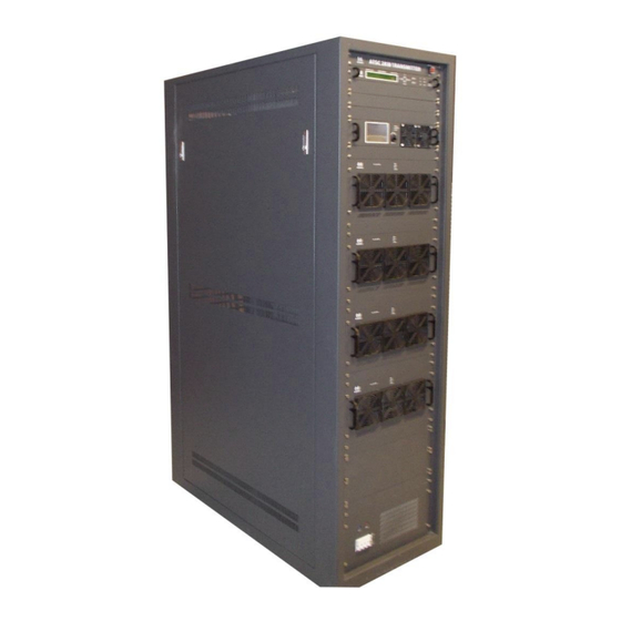
ATSC 2KW TX Quick Start Guide 4 TX System Description The Anywave ATSC 2KW DTV Transmitter comes in single and dual exciter configurations. Photos of a single exciter system are shown below. The main subsystems (as seen from the front) include the Exciter, Controller unit (with a touchscreen LCD, and built-in preamp), four 600W power amplifiers, an AC Mains Breaker, and a channel mask Band Pass Filter (BPF) - optional. - Page 9 ATSC 2KW TX Quick Start Guide From the rear view of the TX cabinet, several other main components can be seen which include a 4-way Splitter, 2-port Directional Coupler, 4-Way Combiner, Reject Loads, and AC Distribution System. 4-Way Splitter 2-Port...
-
Page 10: Tx System Interconnect
ATSC 2KW TX Quick Start Guide 5 TX System Interconnect The diagram below shows the overall system interconnect between the various modules. ACT-2000-QSG-DOC-V1.6, 9/12/2014 Page 10 of 24... -
Page 11: Rf System Connections
1. Mechanically mount BPF on top of TX cabinet If you purchased an Anywave BPF, it is designed to be installed and mounted on top of the 2KW TX cabinet (as shown below). Four metal stand-offs “feet” with mounting hardware are supplied with the BPF to allow it to be fastened and secured to four holes located in the top panel of the cabinet. - Page 12 ATSC 2KW TX Quick Start Guide 2. Connect Elbow and Directional Couplers With the BPF set on top of the cabinet, connect the 90º Elbow between the TX output stack and the BPF Input (Before filter) Directional Coupler (as shown above).
-
Page 13: Ts Input Stream Connection
ATSC 2KW TX Quick Start Guide 7 TS Input Stream Connection With the RF output connections properly made, the next step is to connect your 19.39 MBPS TS input stream to the Exciter inside the TX cabinet. Using a 75ohm cable, connect your ASI input stream to the TS IN 1 BNC connector on the rear panel of the Exciter (as shown below). -
Page 14: Ac Mains Connections
ATSC 2KW TX Quick Start Guide 8 AC Mains Connections Please review the safety WARNINGS on page 4 of this manual before proceeding with any electrical work. A licensed Electrician is required to properly and safely connect the 208V or 220V... - Page 15 ATSC 2KW TX Quick Start Guide 208VAC 3-phase Electrical Requirements The 2KW ATSC Transmitter cabinet may be wired for 208VAC three-phase power to be sourced from a 50A 3-pole breaker. A 4-wire gauge 6 cable is recommended to make the connection between the TX AC Mains Distribution terminal block and the 3- pole 50A breaker in the facility electrical panel.
- Page 16 ATSC 2KW TX Quick Start Guide 220VAC Single-phase Electrical Requirements The 2KW ATSC Transmitter cabinet may be wired for 220VAC single-phase power to be sourced from a 60A 2-pole breaker. A 3-wire gauge 4 cable is recommended to make the connection between the TX AC Mains Distribution terminal block and the 2-pole 60A breaker in the facility electrical panel.
-
Page 17: Initial Turn On
ATSC 2KW TX Quick Start Guide 9 Initial Turn On Once the RF connections have been properly made into your antenna feed or suitable station load, and the Transmitter has been properly wired to the station electrical panel (as outlined in sections 6 & 8) you are now ready to turn on the system. - Page 18 ATSC 2KW TX Quick Start Guide It takes about 5 seconds for the Controller to power up and display the HOME screen (shown below). Please note that the values will be different as the TX initially turns ON at a reduced power level.
- Page 19 ATSC 2KW TX Quick Start Guide 3. You are now ready to bring the TX up to power. To accomplish this, slowly increase the drive level out of the Exciter by increasing the POWER setting in the Exciter RF submenu while watching the Sys FWD power increase accordingly on the Controller touchscreen.
- Page 20 ATSC 2KW TX Quick Start Guide 5. Continue to slowly raise the FWD power until you reach the full 2000W, or your desired TPO. Be careful to make small increases in the value of POWER as you approach the desired output level.
- Page 21 ATSC 2KW TX Quick Start Guide 8. Navigate to the AGC screen on the Controller (by pressing the CONFIG button and then the AGC button). Be sure the AGC Target FWD power is set to 2000W, or whatever TPO level is desired for operation, and then press the unlit AGC button to engage the TX AGC and turn this button Green.
- Page 22 ATSC 2KW TX Quick Start Guide 10. For Dual Drive TX configurations, test the Exciter switchover behavior by pressing the A/B icon on the Controller touchscreen and initiating an Exciter Changeover by selecting EXCITER B, and confirming the changeover when asked. The power will drop and the exciter changeover will initiate.
- Page 23 ATSC 2KW TX Quick Start Guide ipaddresses are user configurable via their respective user interfaces (please refer to the Exciter and 1KW TX User Manuals for details). If you desire to have remote monitoring and control, before leaving the station, please be sure to set the Transmitter to REMOTE mode via the Controller CONTROL button setting and set the Exciter to REMOTE mode under the SYSTEM submenu by setting CTL=RMT.
- Page 24 ATSC 2KW TX Quick Start Guide Anywave Communication Technologies Inc. 300 Knightsbridge Parkway, Suite 150, Lincolnshire, IL 60069 Tel: (847) 415-2258 Fax: (847) 415-2112 Email: sales_us@anywavecom.com http://www.anywavecom.com/en/ ACT-2000-QSG-DOC-V1.6, 9/12/2014 Page 24 of 24...
Need help?
Do you have a question about the ATSC 2KW and is the answer not in the manual?
Questions and answers