
Related Manuals for Froggit HP2000


Summary of Contents for Froggit HP2000
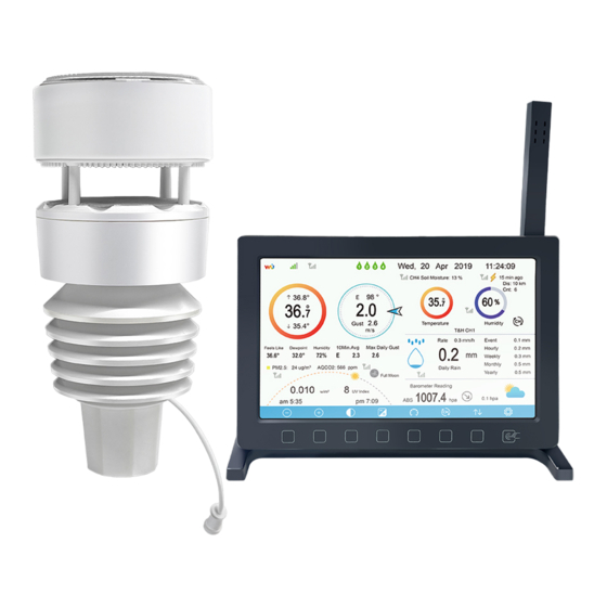
- Page 1 HP2000 7-In-1 Ultra WiFi Internet Wireless Weather Station Manual EN Support/updates/manuals/spare parts: www.froggit.de...
-
Page 2: Table Of Contents
Table of Contents 1 TABLE OF CONTENTS ....................2 WARNINGS AND CAUTIONS..................3 UNPACKING......................... 4 OVERVIEW ........................4.1 D .................. 7 ISPLAY CONSOLE 4.2 O : ................8 UTDOOR SENSOR 4.3 O ................9 PTIONAL SENSORS 5 SET UP GUIDE ......................5.1 P .............. - Page 3 5.6.7 Rainfall unit.................. 35 5.6.8 Solar Rad. Unit ................35 5.6.9 Multi Channel Sensor ..............35 5.6.10 Backlight setting ................ 37 5.6.11 Longitude: Latitude setting ............38 5.6.12 Reset Weekly Rain ..............39 5.6.13 Rainfall season (default: January) ..........39 5.6.14 Storing Interval (1-240minutes Selectable) .......
- Page 4 6.5 W ....... 82 EATHER ORECASTING ESCRIPTION AND IMITATIONS 6.6 M ..................82 HASE 7. TROUBLESHOOTING GUIDE ..................SPECIFICATIONS ....................
-
Page 5: Warnings And Cautions
Warnings and Cautions Warning: Any metal object may attract a lightning strike, including your weather station mounting pole. Never install the weather station in a storm. Warning: If you are mounting the weather station to a house or structure, consult a licensed electrician for proper grounding. A direct lightning strike to a metal pole can damage or destroy your home. -
Page 6: Unpacking
Unpacking Open your weather station box and inspect that the contents are intact (nothing broken) and complete (nothing missing). Inside you should find the following: Item Description Display Console Outdoor Sensor Array with built-in: Thermo-hygrometer / Rain Gauge / Wind Speed Sensor/ Wind Direction Sensor, Light and UV sensor, Solar panel AC adapter White O-ring... -
Page 7: Overview
Overview Display console Figure 1: Display console Temperature, humidity and barometric 3-in-1 sensor 2. Micro SD card slot 3. USB Port 4. Power jack Table 1: Display console identification Note: The USB port in the console of weather station is only for firmware update, not for data communication (USB cable not included). -
Page 8: Outdoor Sensor
4.2 Outdoor sensor: Figure 2: Wireless Sensor Array 1. Solar Panel 7. Hapitac Rainfall sensor 2. Ultrasonic wind sensor 8. NORTH alignment indicator 3. Temperature & humidity sensor 9. Battery compartment 4. Fixed Bolt (Mounting on a pole 10. Heating power cable connector with 1 inch diameter) 5. -
Page 9: Optional Sensors
Optional sensors The following optional sensors (purchased separately) can be used with ) can be used with HP2000 console display. If you have purchase extra sensors, just simple power up, the display console power up, the display console will receives the data automatically. If sensor not reporting in to console... - Page 10 DP150 wire probe thermometer for water DP35 and DP150 share the 8 channels To pair the optional sensors with the HP2000 console, please follow the console, please follow the below operations: 1. Place the optional sensor next to the console (keep 5-10ft away from each 10ft away from each other).
- Page 11 5. In the Sensors ID Setup page, find the sensor you want to pair - select the ID number box and register it. 6. Once successfully, you may return to the main interface to check the data. Note:For above optional sensors 1.
-
Page 12: Set Up Guide
Set up Guide 5.1 Pre Installation Checkout To complete assembly you will need a Philips screwdriver (size PH0) and a wrench (size M5; included in package). Before installing the weather station on the place of operation, we recommend placing the weather station at a temporary location with easy access for one week. -
Page 13: Mount Ultrasonic Anemometer With Piezoelectric Assembly
Figure 3: Battery installation diagram Note: If no LED light up or is lighted permanently, make sure the battery is inserted the correct way or a proper reset is happened. Do not install the batteries backwards. You can permanently damage the outdoor sensor We recommend lithium batteries for cold weather climates, but alkaline batteries are sufficient for most climates. - Page 14 1. Put the white O-ring on the out of the upper part of outdoor sensor array for protection against moisture or water penetrated inside 2. Mounting on a pole as Figure 4. Make sure the mounting pole is vertical, or very close to it. Use a level as needed. Note: Supports poles 1”...
- Page 15 here is an arrow icon with”N” words (Figure 5) representing the direction of North. The sensor body has to be adjusted so that the “N” indication is facing to real north direction in your location. A compass device is recommended to help adjust direction. Permanent wind direction error will be introduced when the outdoor sensor is not installed in right direction.
- Page 16 Note: The outdoor rated adapter and extended power cable can be purchased separately: Accessory Part only, not included! Figure 6: Sensor package mounting diagram 5.2.3 Reset Button and Transmitter LED In the event the sensor package is not transmitting, reset the sensor. Using a bent-open paperclip, press and hold the RESET BUTTON to affect a reset: the LED turns on while the RESET button is depressed, and you can now let go.
-
Page 17: Best Practices For Wireless Communication
After the product works normally, use a cloth or sponge with good water absorption (prevent the echo of the ultrasonic waves) to completely wrap the air inlet. With an open ended paperclip, press and hold the CAL button for three seconds, the top LED light will be on. -
Page 18: Console Display
The following table shows different transmission media and expected signal strength reductions. Each “wall” or obstruction decreases the transmission range by the factor shown below. Medium RF Signal Strength Reduction Glass (untreated) 5-15% Plastics 10-15% Wood 10-40% Brick 10-40% Concrete 40-80% Metal 90-100%... - Page 19 Figure 7: Display Console Screen Layout Description Description Outdoor temperature Last lightning strikes detected time / distance; daily counts (optional sensor) Outdoor Feels Like/Dew Indoor humidity point/Humidity/10Min. Average Wind Direction/Max Daily Gust PM2.5 concentration(optional RF signal bar for multi-channel sensor) temperature and humidity sensor(optional sensor)
-
Page 20: Initial Display Console Set Up
RF signal bar for PM2.5 Multi-channel temperature and sensor(optional sensor) humidity sensor cycle display mode icon(optional sensor) Sunrise / Sunset Time Multi-channel temperature and humidity sensor channel number (optional sensor) Wi-Fi signal bar Rain fall Daily/Event/Hourly/Weekly/ Monthly/Yearly Low battery power indicator for RF signal bar for Rain fall each sensor sensor(optional sensor) - Page 21 Dark Background Display Light Background Display Note: Sunrise/sunset time display will only work properly when GEO Sunrise/sunset time display will only work properly when GEO location has been set up correctly. GEO setup can be carried out under setup location has been set up correctly. GEO setup can be carried out under setup menu.
-
Page 22: Key Functions
5.4.2 Key functions Figure 8: Buttons around the display There is a set of eight keys on the bottom of the display console. The following table briefly explains the function of these keys. Icon Description Brightness control key Press this key to decrease the brightness Brightness control key Press this key to enhance the brightness Backlight on/off key... -
Page 23: Main Interface Icons Explain
5.4.3 Main interface icons explain 5.4.3.1 Temperature Icon Temperature Range Color Temperature Range Temperature Range Color (degF) Ring (degF) Ring < -10 50-60 -10 to 0 60-70 0 to 10 70-80 10-20 80-90 20-30 90-100 30-40 100-110 40-50 > 110... - Page 24 5.4.3.2 Humidity Icon Humidity Range Color Ring Humidity Range Color Ring 0%, No signal or 50 to 60 dashes 1 to 10 60 to 70 10 to 20 70 to 80 20 to 30 80 to 90 30 to 40 90 to 99 40 to 50 100%...
-
Page 25: Multiple Channel Selection And Scroll Mode
5.4.3.4 Hourly Rainfall Icon Hourly Rain (in) Icon Hourly Rain (in) Icon 0.6 to 0.8 0 to 0.2 0.8 to 1 0.2 to 0.4 1 to 1.2 0.4 to 0.6 1.2 to 1.4 5.5 Multiple Channel Selection and Scroll Mode Multi-channel sensors are optional sensors, not included in the package. - Page 26 Figure 9: Max/Min Screen Icon Description Selection key Press this key to select the weather MAX/MIN record which need to clear Selection key Press this key to select the weather MAX/MIN record which need to clear Enter key While the desired weather MAX/MIN record selected , press this key to popup Message Box ”Clear the Max/Min record?”.
-
Page 27: History Record Mode
History key Press this key to select History data display. Return key Press this key to return to normal display mode 5.5.2 History Record Mode While in normal display, press the key twice to enter History Record key twice to enter History Record Mode. - Page 28 Page down key Press this key to scroll down the page you are viewing Press this key to scroll down the page you are viewing History key Press this key to select the Max/Min record or History. Press this key to select the Max/Min record or History. Return key Press this key to return to previous mode 5.5.2.1 Clear the history record...
-
Page 29: View Graph
Figure 12: view a specific page of history Screen view a specific page of history Screen Press to select a digit in a number, press to change the number. Press to change the activated option to change the activated option field, toggle OK or Cancel then press key to confirm. -
Page 30: View Channel Data
Figure 13: Graph Screen Press to shift the data display of 12/24/48/72H. Press . Press to view the graph of the following data: Indoor outdoor temperature Dew Point and Feels like Indoor outdoor humidity Wind speed and Gust ... -
Page 31: Setting Mode
multi-channel temperature and humidity sensor, their data can be showed on sensor, their data can be showed on Channel Data screen. Press key to select Name setting field, the name on focus turns key to select Name setting field, the name on focus turns green, press the key to pop up the keyboard to enter the sensor key to pop up the keyboard to enter the sensor... - Page 32 can select the below sub-mode by pressing the Figure 15: Setup Menu Screen Icon Description Select key Press this key to select the unit or scrolls the value Select key Press this key to select the unit or scrolls the value. Left key Press this key to select the set value.
-
Page 33: Date And Time Setting
Return key Press this key to return to previous mode 5.6.1 Date and Time setting While in Menu Setting Mode, press key to select Date and Time key to select Date and Time Setup field, press key to enter Date and Time Setup mode: key to enter Date and Time Setup mode: Figure 16: Time and date Setup Screen Time setting (hour/minute/second) -
Page 34: Time Format Setting
Date setting Press key to select Date setting field, the day digit on focus turns red, press the key to change the day setting. Press to set the month, then month digit focused will turn red, press the key to change the month setting. Press to set the year, the year digit on focus will turn red, press the key to change the year... -
Page 35: Date Format Setting
5.6.3 Date Format setting Press to change the time format between DD-MM–YYYY, YYYY-MM- DD and MM-DD-YYYY 5.6.4 Temperature unit setting Press to change the temperature units of measure between °F and °C. 5.6.5 Barometric unit Press to change the temperature units of measure between inHg, mmHg and hpa 5.6.6 Wind speed unit Press... - Page 36 Figure 17: Multi channel sensor Setup Screen Press key to select Name setting field, the name on focus turns key to select Name setting field, the name on focus turns green, press the key to pop up the keyboard to enter the sensor key to pop up the keyboard to enter the sensor name.
-
Page 37: Backlight Setting
Press key to select Register setting field, press the , press the key to register the selected sensor 5.6.10 Backlight setting While in Menu Setting Mode, press key to select Backlight Setup field, key to select Backlight Setup field, press key to enter backlight Setup mode: Figure 19: Backlight Setting Screen Automatic control backlight: select this option, the backlight will auto turn... -
Page 38: Longitude: Latitude Setting
Minimum brightness: set the minimum brightness while it is the weakest light intensity Icon Description Select key Press this key to select the unit or scrolls the value Select key Press this key to select the unit or scrolls the value. Left key Press this key to select the set value. -
Page 39: Reset Weekly Rain
Figure 20: Longitude and Latitude Setting Screen : Longitude and Latitude Setting Screen The sunrise/sunset times will be calculating automatically base on the The sunrise/sunset times will be calculating automatically base on the Longitude and Latitude. Your location GEO info can be found on mobile location GEO info can be found on mobile compass page. -
Page 40: Weather Server
5.6.15 Weather Server Your console is capable of sending your sensor data to select internet-based weather services. The supported services are shown in the table below: Service Website Description Ecowitt https://www.ecowitt.net Ecowitt is a new weather server Weather that can host a bunch of sensors that other services... -
Page 41: Wunderground Server Setup
5.6.15 .1 Wunderground server setup Perform the following steps to get the Station ID and Password get the Station ID and Password on wunderground.com: Visit Wunderground.com and select the Join link at the top of the page link at the top of the page and sign up. - Page 42 Find Personal Weather Station. Select ‘other’ and click ‘Next’. Find Personal Weather Station. Select ‘other’ and click ‘Next’. Select ‘Address’ or ‘Manual’ option, and find your local position. Press ‘Address’ or ‘Manual’ option, and find your local position. Press ‘Next’.
- Page 43 This time you will be asked details about your weather station. Go ahead This time you will be asked details about your weather station. Go ahead and fill out the form.
- Page 44 After completing the weather station, you will see station ID and After completing the weather station, you will see station ID and key/password. Take note of the station ID and key/password and enter it in the Take note of the station ID and key/password and enter it in the Weather Server: Figure 21: WU Server setup screen...
- Page 45 15. scroll 16. scroll 17. Scroll 18. Scroll 19. return value value field field down down Setup 1) Set Station ID: Press to highlight the Station ID. Enter your to highlight the Station ID. Enter your station ID. Press to display the keyboard. Press to display the keyboard.
- Page 46 character and press to select the character. Press the “OK” Press the “OK” button to confirm..Press to return to the setup page. to return to the setup page. 9. Refresh the page, you may have to wait about a few minutes until the Refresh the page, you may have to wait about a few minutes until the status becomes ‘Online’.
- Page 47 There are also some very useful mobile apps. The URLs provided here go to the Web version of the application pages. You can also find them directly from the iOS or Google Play stores: WunderStation: iPad application for viewing your station’s data and graphs https://itunes.apple.com/us/app/wunderstation-weather-from-your-neigh borhood/id906099986 WU Storm: iPad and iPhone application for viewing radar images, animated...
- Page 48 https://itunes.apple.com/us/app/wu-storm/id955957721 Weather Underground: Forecast: iOS and Android application for : iOS and Android application for forecasts https://itunes.apple.com/us/app/weather-underground-forecast/id486154808 forecast/id486154808 https://play.google.com/store/apps/details?id=com.wunderground.android.w https://play.google.com/store/apps/details?id=com.wunderground.android.w eather&hl=en...
- Page 49 PWS Weather Station Monitor: View weather conditions in your neighborhood, or even right in your own backyard. Connects to wunderground.com https://itunes.apple.com/us/app/pws-weather-station-monitor/id713705929...
-
Page 50: Weathercloud Server Setup
5.6.15.3 Weathercloud server setup To register with Weathercloud follow these steps: Visit weathercloud.net and enter a Username, Email and Password to and enter a Username, Email and Password to sign up. Respond to the validation email from Weathercloud (it may take a few Respond to the validation email from Weathercloud (it may take a few minutes). - Page 51 You will then be prompted to add a device/ Select “Create device” a You will then be prompted to add a device/ Select “Create device” and enter your station’s information: After registering your station, take note of the “Weathercloud ID” and After registering your station, take note of the “Weathercloud ID”...
- Page 52 Weather Observations Website (WOW) server setup server setup 5.6.15.4 To have your weather station upload data to the Met Office’s WOW site you To have your weather station upload data to the Met Office’s WOW site you will need to complete the following steps: Sign Up with WOW Navigate your browser to http://wow.metoffice.gov.uk.
- Page 53 The actual form is longer, but all questions should be self The actual form is longer, but all questions should be self-explanatory. Complete and submit the form. You will receive the following notice on submit the form. You will receive the following notice on completion: Confirm your email with WOW Respond to the validation email from WOW(it may take a few minutes).
- Page 54 You will be presented with a form where you detail your station’s location ou detail your station’s location and a bunch of other settings related to how you wish the site to operate. After and a bunch of other settings related to how you wish the site to operate. After you complete the setup, you should see: Make sure you are (still) logged in to the WOW site.
- Page 55 You will need both “Site ID” and “Authentication Key” to setup the upload Key” to setup the upload configuration for WOW in the Weather Server. Figure 22: WOW Server setup screen scroll value scroll value Scroll field Scroll field return to down down Setup...
- Page 56 Ecowitt.net server setup 5.6.15.5 Figure 23: Ecowitt Server setup screen scroll value scroll value Scroll field Scroll field return to down down Setup To register with Ecowitt follow these steps: 1) On the Weather Server page, set the reporting interval time set the reporting interval time(default: 1 minute).
- Page 57 Note: When select device address on map, please wait till the map display Note: When select device address on map, please wait till the map display before select your address. Note: Please put in the correct time zone to get the correct time. Because the Note: Please put in the correct time zone to get the correct time.
- Page 58 Dashboard Graph display List display...
- Page 59 Weather Map Email Alerts...
- Page 60 Ecowitt.net is a responsive design and mobile friendly. Simply open your Ecowitt.net is a responsive design and mobile friendly. Simply open your mobile devices web browser, browse to ecowitt.net, and bookmark your mobile devices web browser, browse to ecowitt.net, and bookmark your dashboard for quick access.
-
Page 62: Wi-Fi Scan
5.6.16 Wi-Fi scan Figure 25: Select Wi-Fi Network Screen Press key to select the Wi-Fi network. Press key to confirm and enter the password. Press key to return to normal display key to return to normal display mode. It is possible that your network is not listed when Wi-Fi Scan is Fi Scan is performed. - Page 63 1) Press to select Hidden SSID setup, and press to select Hidden SSID setup, and press directly to enter. 2).Press to highlight the SSID. Press to display the keyboard and to display the keyboard and enter your SSID. Press to scroll to the character and to scroll to the character and press to enter the character.
-
Page 64: Reset Daily Rain
5.6.17 Reset Daily Rain While in Menu Setting Mode, press key to select Reset Daily Rain Reset Daily Rain Setup field, press key to Reset Daily Rain begin it from 00:00 Reset Daily Rain begin it from 00:00 to 23:00 ,Default in 00:00 5.6.18 More This screen is for optional sensors calibration and sensors ID setup. - Page 65 Figure 26: optional sensors calibration and sensor ID setup Screen ID setup Screen Press key to select setting field, press the key to enter option sensors calibration mode or Sensor ID setup mode. sensors calibration mode or Sensor ID setup mode. Figure 27: Soil Moisture Calibration Screen...
- Page 66 Figure 28: Multi-channel Temperature and Humidity channel Temperature and Humidity Sensor calibaration Screen Figure 29: PM2.5 Air Quality Sensor Calibration Screen Screen...
- Page 67 Figure 30: PM2.5, PM10 and CO2 Air Quality Sensor Calibration PM2.5, PM10 and CO2 Air Quality Sensor Calibration Note: To calibrate the optional soil moisture sensor, please refer to the manual of the To calibrate the optional soil moisture sensor, please refer to the manual of the WH51 soil moisture senor.
- Page 68 Figure 31: Sensors ID setup Screen This screen list all sensors can work with HP2564 console. T This package just included WS90 outdoor sensor array and T&HP (Temperature, humidity and array and T&HP (Temperature, humidity and pressure) indoor sensor. These two sensors signal reception status and ID pressure) indoor sensor.
- Page 69 The sensor ID is unique and fixed. You can choose Disable Disable to disconnect with console, or Register to reconnect with console.
-
Page 70: Alarm Setting Mode
pop up the pop up the Scroll field Scroll field Scroll field return to keyboard or keyboard or down Setup confirm the confirm the operation operation 5.7 Alarm Setting Mode Figure 32: Alarm Setting Screen... -
Page 71: Calibration Mode
Icon Description Select key Press this key to select the unit or scrolls the value Press this key to select the unit or scrolls the value Select key Press this key to select the unit or scrolls the value. the value. Left key Press this key to select the set value. - Page 72 Figure 33: Calibraton Setting Screen Icon Description Select key Press this key to select the unit or scrolls the value Select key Press this key to select the unit or scrolls the value. Left key Press this key to select the set value. Right key Press this key to select the set value.
- Page 73 Wind Offset Current GPS, Compass (4) Direction Value Solar Gain 1.00 Calibrated laboratory grade solar radiation Radiation sensor 1 w/m Gain 126.7 Solar radiation conversion from lux to for wavelength correction (5) Gain 1.00 Calibrated laboratory grade UV sensor Wind Gain 1.00 Calibrated laboratory grade wind meter (6)
- Page 74 over time due to contamination. In addition, location has an adverse affect on humidity readings (installation over dirt vs. lawn for example). Official stations recalibrate or replace humidity sensors on a yearly basis. Due to manufacturing tolerances, the humidity is accurate to ±...
- Page 75 (5) The default conversion factor based on the wavelength for bright sunlight is 126.7 lux / w/m . This variable can be adjusted by photovoltaic experts based on the light wavelength of interest, but for most weather station owners, is accurate for typical applications, such as calculating evapotransporation and solar panel efficiency.
-
Page 76: Factory Reset
RTD, the humidity sensor is a capacitance device), mechanical variation, or RTD, the humidity sensor is a capacitance device), mechanical variation, or degradation (wearing of moving parts, contamination of sensors). degradation (wearing of moving parts, contamination of sensors). Calibration is only useful if you have a known calibrated source you Calibration is only useful if you have a known calibrated source you can compare it against, and is optional. -
Page 77: Re-Register Indoor Transmitter
5.9.1 Re- indoor transmitter register Press key to select re-register indoor transmitter. Press key to popup the Message Box ”Register a new indoor transmitter?” Press to select Yes or No. Press the key to confirm the selection. 5.9.2 Re-register outdoor transmitter Please reference section 6.7.1. -
Page 78: Clear Max/Min
popup the Message Box ”Clear the history record?” Press select Yes or No. Press the key to confirm the selection. 5.9.6 Clear Max/Min Press key to select Clear Max/Min. Press to popup the Message Box ”Clear the max/min record?” Press to select Yes or No. -
Page 79: About Information
5.9.8 About information Figure 35: About information Screen Note: This figure is just for reference(model and frequency will change according to different market). The actual display console may be with higher firmware version than this manual described because we will update the firmware occasionally. -
Page 80: Uvi Range
Wind speed Beaufort Description number 0 - 1 mph, or 0 - 1.6 km/h Calm 1 - 3 mph, or 1.6 - 4.8 km/h Light air 3 - 7 mph, or 4.8 - 11.3 km/h Light breeze 7 - 12 mph, or 11.3 -1 9.3 km/h Gentile breeze 12 - 18 mph, or 19.3 - 29.0 km/h Moderate breeze... -
Page 81: Weather Forecasting
4196 - 4707 uW/cm2 Very high 4707 - 5209 uW/cm2 Extreme 5209 - 5735 uW/cm2 Extreme 5735 - 6276 uW/cm2 Extreme 6276 - 6778 uW/cm2 Extreme 6778 uw/cm2 and above Extreme 6.3 Weather Forecasting The seven weather icons are Sunny, Partly Cloudy, Cloudy, Rainy, Stormy, Snowy and Storm Snowy. -
Page 82: Lightning Alert
Note: When outdoor temperature is below 0 and the forecast is Rainy or Stormy, the LCD will display Snowy and Storm Snowy 6.4 Lightning Alert The lightning icon will appear if the Dew Point exceeds 70 F. This means there is a chance of lightning storms forming. 6.5 Weather Forecasting Description and Limitations In general, if the rate of change of pressure increases, the weather is generally improving (sunny to partly cloudy). - Page 83 Day 1 Day 14 Day 2 Day 15 Day 3 Day 16 Day 4 Day 17 Day 5 Day 18 Day 6 Day 19 Day 7 Day 20 Day 8 Day 21 Day 9 Day 22 Day 10 Day 23 Day 11 Day 24 Day 12...
- Page 84 7. Maintainance Replacing Batteries Regularly The Temperature and Humidity Sensor Kit can be replaced whenever required. Use screwdriver to 2. Unplug the old sensor uptight the screws of the sensor. 3. Replace the old Temp & Humidity sensor with new one...
- Page 86 8. Troubleshooting Guide Look through the following table and locate an issue or problem you are experiencing in the left column and read possible solutions in the right column. Problem Solution Outdoor sensor array The sensor array may have initiated properly and does not communicate to the data is registered by the console as invalid, the display console.
- Page 87 Problem Solution sensor array and the console has not been reset. The solution may be as simple as powering down and up the console. Replace the batteries in the outside sensor array. With the sensor array and console 10 feet away from each other, remove AC power from the display console and wait 10 seconds.
- Page 88 Problem Solution 2. Confirm your station ID is correct. The station ID is all caps, and the most common issue is substituting an O for a 0 (or visa versa). Example, KAZPHOEN11, not KAZPH0EN11 3. Make sure the date and time is correct on the console.
- Page 89 8. Specifications Note: Out of range values will be displayed using “---”: Outdoor sensor Specification Transmission distance 150 m (450 ft.) open field RF Frequency 868MHz Temperature range -40°C – 60°C (-40°F - 140°F) Temperature accuracy ± 0.3°C, or ± 0.6°F Temperature resolution 0.1°C, or 0.1°F Humidity range...
- Page 90 Indoor sensor Specification Temperature range -10°C – 60°C (14°F - 140°F) Temperature resolution 0.1°C, or 0.1°F Humidity range 10% ~ 99% Humidity resolution Barometric pressure range 300 – 1,100 hPa (8.85 – 32.5 inHg) Barometric pressure accuracy ± 5 hPa in 700 – 1,100 hPa range Barometric pressure resolution 0.1 hPa (0.01 inHg) Sensor reporting interval...
- Page 91 Caution ! This booklet may contain errors or misprints. The information is contains is regularly checked and correction are included in subsequence editions. We disclaim any responsibility for any printing error, or their consequences. The specification of this product may change without prior notice. General safety instructions Danger of asphyxiation: Keep all packaging materials (plastic bags, rubber bands, etc.) away from...
- Page 92 This manual may contain errors and misprints. However, the information in this manual is regularly reviewed and corrections made in the next issue. We accept no liability for technical errors or printing errors, and their consequences. All trademarks and copyrights are acknowledged. www.froggit.de...
- Page 93 Hereby we declare, HS-Group GmbH & Co.KG, Escherstr. 31, 50733 D-Cologne, that this product is in compliance with the essential requirements and other relevant provisions of Directive 2014/53/EU. The declaration of conformity for this product can be found www.froggit.de or on request.
Need help?
Do you have a question about the HP2000 and is the answer not in the manual?
Questions and answers