Table of Contents
Advertisement
Quick Links
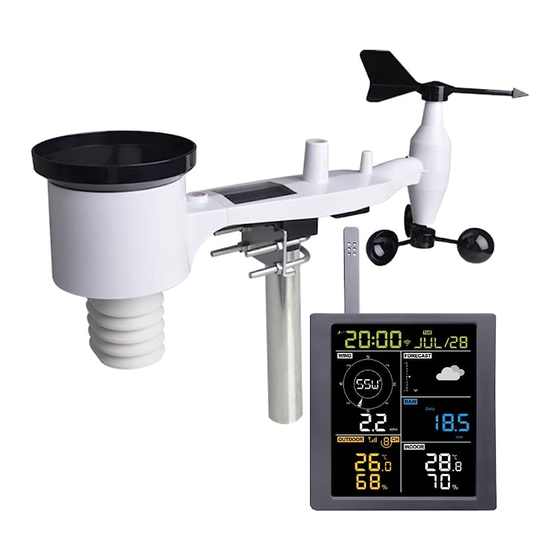
WH3900 Multi-channel WiFi Internet wireless
Table of Contents
1. Introduction ........................................................................................ 3
2. Warnings and Cautions ........................................................................ 3
3. Quick Start Guide................................................................................ 3
4. Pre-Installation Checkout and Site Survey ............................................. 4
4.1 Pre Installation Checkout .................................................................. 4
4.2 Site Survey ...................................................................................... 4
5. Setting Started .................................................................................... 4
5.1 Contents .......................................................................................... 4
5.2 Sensor Array Set Up ......................................................................... 5
5.2.1 Install U-bolts and mounting pole ............................................... 6
5.2.2 Install wind vane ....................................................................... 7
5.2.3 Install wind speed ...................................................................... 7
5.2.4 Install Rain Gauge ..................................................................... 8
5.2.5 Install Batteries ......................................................................... 8
5.2.6 Mount assembled outdoor sensor package ................................ 9
5.2.7 Reset Button and Transmitter LED ........................................... 10
5.3 Optional sensors ............................................................................. 11
5.4 Indoor/Outdoor Thermo-Hygrometer, 8 Channel (optional) ............... 13
5.5 Best Practices for Wireless Communication ..................................... 14
5.6 Display console ............................................................................. 15
6. Display Console Operation ................................................................ 17
6.1 Screen Display .............................................................................. 17
6.2 Initial Display Console Set Up ........................................................ 17
6.2.1 Key function ........................................................................... 18
6.3 Setting mode ................................................................................. 19
6.4 Barometric Pressure Display ........................................................... 21
6.4.1 Viewing Absolute vs. Relative Pressure ..................................... 21
6.4.2 Rate of Change of Pressure Graph ............................................ 22
6.4.3 Relative Pressure Calibration Discussion ................................... 22
6.5 Rain Display ................................................................................. 23
6.5.1 Rain Increments of Measure ..................................................... 23
6.5.2 Increments of Rain Definitions ................................................. 23
6.6 Wind Display ................................................................................ 23
6.7 Temperature Display ...................................................................... 24
Weather station
5.2.6.1 Before you mount ................................................. 9
5.2.6.2 Mounting ............................................................. 9
1
Advertisement
Table of Contents

Subscribe to Our Youtube Channel
Related Manuals for Froggit WH3900


Summary of Contents for Froggit WH3900
-
Page 1: Table Of Contents
WH3900 Multi-channel WiFi Internet wireless Weather station Table of Contents 1. Introduction ..................3 2. Warnings and Cautions ................ 3 3. Quick Start Guide................3 4. Pre-Installation Checkout and Site Survey ..........4 4.1 Pre Installation Checkout ..............4 4.2 Site Survey ..................4 5. - Page 2 6.7.1 Wind Chill, Dew Point and Heat Index Display ......24 6.8 Alarms ..................24 6.8.1 Viewing High and Low Alarms ..........24 6.8.2 Setting High and Low Alarms........... 25 6.9 Max/Min Mode ................29 6.9.1 Viewing Max/Min Values ............29 6.9.1.1 Display Wind Chill, Heat Index vs.
-
Page 3: Introduction
1. Introduction Thank you for your purchase of the Wireless Wi-Fi Weather Station, which is designed with the latest low power Wi-Fi technology, which can be operated with 2pcs AA batteries, and it works up to 6 months. The following user guide provides step by step instructions for installation, operation and troubleshooting. -
Page 4: Pre-Installation Checkout And Site Survey
Register and upload to Weather Server Table 1: Quick Start Guide 4. Pre-Installation Checkout and Site Survey 4.1 Pre Installation Checkout Before installing your weather station in the permanent location, we recommend operating the weather station for one week in a temporary location with easy access. -
Page 5: Sensor Array Set Up
Display Console Outdoor Sensor with built-in: Thermo-hygrometer / Rain Gauge / Wind Speed Sensor/ Wind Direction Sensor Wind speed cups (to be attached to outdoor sensor body) Wind vane (to be attached to outdoor sensor body) U-Bolts for mounting on a pole Threaded nuts for U-Bolts (M6 size) Metal mounting plate to be used with U-Bolts Wrench for M6 bolts... -
Page 6: Install U-Bolts And Mounting Pole
1 Wind speed cups 6 Antenna 2 Wind vane 7 U-Bolts 3 Thermo- and hygro-meter sensors 8 Battery compartment door 4 Rain collector 9 Reset button 5 Bubble level 10 LED (red) to indicate data transmission Table 3: Sensor assembly detailed items 5.2.1 Install U-bolts and mounting pole Installation of the U-bolts, which are in turn used to mount the sensor package on a pole, requires installation of an included metal plate to receive the U-bolt... -
Page 7: Install Wind Vane
The plate and U-Bolts are not yet needed at this stage but doing this now may Bolts are not yet needed at this stage but doing this now may help avoid damaging wind vane and wind speed cups later on. 5.2.2 Install wind vane Push the wind vane onto the shaft on the bottom of the sensor, of the sensor, until it stops... -
Page 8: Install Rain Gauge
5.2.4 Install Rain Gauge Install the rain gauge funnel. Rotate clockwise to attach the funnel to the outdoor sensor. Figure 6: Rain gauge installation and maintenance 5.2.5 Install Batteries Insert 2XAA batteries in the battery compartment. The LED indicator on the back of the transmitter will turn on for four seconds and normally flash once every 16 seconds (the sensor transmission update period). -
Page 9: Mount Assembled Outdoor Sensor Package
Figure 7: Battery installation diagram Note: If no LED light up or is permanently on, make sure the batteries are inserted the correct way or a proper reset has happened. Do not install the batteries backwards. You can permanently damage the outdoor sensor. Note: We recommend 1.5V lithium batteries for cold weather climates, but alkaline batteries are enough for most climates. -
Page 10: Reset Button And Transmitter Led
Figure 8: Sensor package mounting diagram Finally, place the sensor package on top of the prepared mounting pipe.The U- Bolts should be loose enough to allow this but loosen the nuts as necessary. Once placed, hand tightens all four nuts, taking care to do so evenly. Now you will need to align the whole package in the proper direction by rotating it on top of the mounting pipe as needed. -
Page 11: Optional Sensors
Figure 9: Reset button and Transmitter LED location 5.3 Optional sensors Important: When more sensors, excluding the original sensor array, to be paired with the display, DC power supply must be applied as console will turn on its RF receiver permanently, which increases the current consumption significantly. - Page 12 Item Number Description Image Number Channels DP200 4 PM2.5 Wireless Indoor Particulate Monitor DP250 1 PM2.5, PM10 and CO Wireless Indoor Particulate Monitor DP100 8 Soil Moisture Sensor DP60 1 Lightning Detector DP70 4 Leak Detector DP35 8* DP150 stainless-steel probe therm DP150 ometer for soil DP35 wire probe thermometer for...
-
Page 13: Indoor/Outdoor Thermo-Hygrometer, 8 Channel (Optional)
The DP35 and DP150 share the same 8-channels. Table 4: Optional sensors list 5.4 Indoor Thermo-Hygrometer, 8 Channel (optional) Hygrometer, 8 Channel (optional) This device supports up to 8 additional thermo-hygrometer sensors ( hygrometer sensors (DP50), the data will scroll display on the console and sends the data to Ecowitt.net Ecowitt.net (requires to set the console uploading to ecowitt.net first). -
Page 14: Best Practices For Wireless Communication
Temperature Units of Measure: To change the transmitter display units To change the transmitter display units of measure (°F vs. °C), change Dip Switch 4, as referenced in of measure (°F vs. °C), change Dip Switch 4, as referenced in Figure . Switch in down position. -
Page 15: Display Console
Wireless communication is susceptible to interference, distance, walls and metal barriers. We recommend the following best practices for trouble free wireless communication. Electro-Magnetic Interference (EMI). Keep the console several feet away from computer monitors and TVs. Radio Frequency Interference (RFI). If you have other devices operating on the same frequency band as your indoor and/or outdoor sensors and experience intermittent communication between sensor and console, try turning off these other devices for troubleshooting purposes. - Page 16 Figure 13: Display console front and back Reference Figure 14. (1) Unfold the desk stand and place the console 5 to 10 feet away from the outdoor sensor. (2) Remove the battery door on the back of the console and insert 2 x AA good quality Alkaline or Lithium batteries per Figure 14.
-
Page 17: Display Console Operation
Figure 14: Battery installation for display console 6. Display Console Operation 6.1 Screen Display Figure 15: Display Console Screen Layout 1.Wind direction 9. Rainfall 2. Wind speed 10. Barometric Pressure graphic 3. RF signal icon 11. Weather forecast 4. 8 Channel Indoor/Outdoor Thermo-Hygrometer recycle icon 12. -
Page 18: Key Function
The unit will show software version and frequency information 2 seconds after power reset. The unit will turn on all segments of the LCD for 3 seconds after power reset, then the unit will start to register the outdoor channel for 3 minutes. Figure 16 6.2.1 Key function The console has five keys for easy operation... -
Page 19: Setting Mode
TEMP(+2s) Press and hold 2s will force console to search sensor manually WIND - Press to switch between average wind speed and, wind gust. Press and hold for two seconds to switch the wind direction to display in degrees or in letters. RAIN/PRE Press and hold for two seconds switch between Rain and ... - Page 20 Command Mode Settings Image Image Enter Set Press [TEMP +] or [WIND -] [MODE] + Mode, to switch OFF and ON. 2 seconds Beep On or This will prevent the beep from sounding when pressing any button. Clear Press [TEMP +] or [WIND -] [MODE] Max/Min to switch OFF and ON.
-
Page 21: Barometric Pressure Display
Relative Press [TEMP +] or [WIND -] [MODE] Pressure to adjust relative pressure up Calibration or down Reference Section 03 for details on calibration of relative pressure. Temperatu Press [TEMP +] or [WIND -] [MODE] re Units of to change temperature units of Measure measure between °F and °C. -
Page 22: Rate Of Change Of Pressure Graph
relative pressure and calibration, reference Section 0. 6.4.2 Rate of Change of Pressure Graph The rate of change of pressure graphic is shown to the left of the weather forecast icons and signifies the difference between the daily average pressure and the 30-day average (in hPa). -
Page 23: Rain Display
6.5 Rain Display 6.5.1 Rain Increments of Measure Press and hold [RAIN/PRE] for two seconds switch between Rain and Pressure. While in Rain mode press the [RAIN/PRE] to switch between Rain Rate (in/hr), Rain Event, Rain Hourly, Daily Rain, Weekly Rain, Monthly Rain and Yearly Rain. -
Page 24: Temperature Display
6.7 Temperature Display If temperature is lower than minimum range, the temperature field will display dashes (--.-). If temperature is higher than maximum range, the temperature field will display dashes (--.-). 6.7.1 Wind Chill, Dew Point and Heat Index Display Press the [TEMP] button to switch between Outdoor Temperature, Wind Chill, Dew Point, Heat Index. -
Page 25: Setting High And Low Alarms
Figure 19 6.8.2 Setting High and Low Alarms While the High Alarm is displayed (reference Section 0), press and hold the ), press and hold the MODE button for 2 seconds to enter the High Alarm Set Mode. MODE button for 2 seconds to enter the High Alarm Set Mode. While the Low Alarm is displayed (reference Section 0), press and hold the ), press and hold the MODE button for 2 seconds to enter the Low Alarm Set Mode. - Page 26 Command Mode Settings Enter High Alarm Press [TEMP +] or [WIND -] to adjust [MODE] + Set Mode, Alarm alarm hour up or down. 2 seconds Hour Press [RAIN/PRE] to turn the time alarm on or off. When the alarm is on, the alarm time icon will appear.
- Page 27 Alarm High Outdoor Press[TEMP +] or [WIND -] to adjust [MODE] Temperature alarm value up or down. Press [RAIN/PRE] to turn the alarm on. The alarm icon will appear. Press [RAIN/PRE] to turn the alarm off. The alarm icon will disappear. Alarm High Outdoor Press [TEMP +] or [WIND -] to adjust [MODE]...
- Page 28 Alarm Low Indoor Press [TEMP +] or [WIND - ]to adjust [MODE] Temperature alarm value up or down. Press [RAIN/PRE] to turn the alarm on. The alarm icon will appear. Press [RAIN/PRE] to turn the alarm off. The alarm icon will disappear. Alarm Low Indoor Press [TEMP +] or [WIND -] to adjust [MODE]...
-
Page 29: Max/Min Mode
6.9 Max/Min Mode 6.9.1 Viewing Max/Min Values To view the max value, press the MODE button, and the max values will be button, and the max values will be displayed, as shown in Figure 20 (a). To clear the max values, press and hold the (a). -
Page 30: Display Hourly Rain, Rain Rate
button once to view the max wind gust, and twice to return to wind speed. o return to wind speed. 6.9.1.3 Display Hourly Rain, Rain Rate While the max values are displayed as outlined in Section 0, press the , press the RAIN button once to view the max hourly rain, twice to view the rain rate. -
Page 31: With Usb Cable (Included)
6.11.1 With USB cable (included) The backlight can only be continuously on when the console display is powered The backlight can only be continuously on when the console display is powered on with the USB cable. Press the LIGHT button to adjust the brightness between High, Middle, Low Press the LIGHT button to adjust the brightness between High, Middle, Low and Off. -
Page 32: Weather Forecasting
6.14 Weather Forecasting The five weather icons are Sunny, Partly Cloudy, Cloudy, Rainy, weather icons are Sunny, Partly Cloudy, Cloudy, Rainy, Stormy and Snowy. The forecast icon is based on the rate of change of barometric pressure. Please The forecast icon is based on the rate of change of barometric pressure. Please allow at least one month for the weather station to learn the barometric pressure for the weather station to learn the barometric pressure over time. -
Page 33: Specification
The reason the current conditions do not match the forecast icon is because the forecast is a prediction 24-48 hours in advance. In most locations, this prediction is only 70% accurate and it is a good idea to consult the National Weather Service for more accurate weather forecasts. -
Page 34: Live Internet Publishing
Measuring range rel. Humidity : 1%~99% Resolution : 1% Measuring range air pressure : 700-1100hPa (20.67-32.5inHg) Accuracy : +/-3hpa Resolution : 0.1hPa (0.01inHg) Alarm duration : 120s Measuring interval indoor data : 60s Power consumption Base station : 5V DC (USB to 2.5*0.7mm DC 5V power plug connector cable included) ... -
Page 35: Configure Wi-Fi Via Ble To Connect The Weather Station Console
Observation gov.uk/ observation website observation website. WOW allows Website anyone to submit their own weather anyone to submit their own weather (WOW) data, anywhere in the world. data, anywhere in the world. Customized Supports uploading to your Supports uploading to your Website customized website, if the website customized website, if the website... - Page 36 Or it is necessary even to switch this option off: Please check your Wi-Fi router or AP devices setting and contact us if you still and contact us if you still have problem in connecting the console to your Wi-Fi network. Fi network.
-
Page 37: Download Mobile Application
8.1.1 Download mobile application Wi-Fi configuration is done using your mobile device, either iOS or Android. Fi configuration is done using your mobile device, either iOS or Android. Start by downloading the WS View Plus application from the Apple App Store application from the Apple App Store or Google Play store, as appropriate for your device. - Page 38 Select the device you Follow the prompts, tick the box Press “+” Configure have from the device list, a New Device” to confirm “completed then press Next operation”, press Next. The app will search If you have more than one device Choose the ID,The app the device.
- Page 39 Upload your data to Press Scan and select your Upload your data to Wunderground.com SSID from the list. www.ecowitt.net Register an account and station If it is a dual band router Tap ON and select an upload at Wuderground.com per and the SSIDs are different, interval in minutes.
- Page 40 Upload your data to your Upload your data to Upload your data to own sever. WeatherCloud.net WeatherObservationsWebsite.net The website should have Register an account and Register an account and station at the same protocol with https://register.metoffice.gov.uk. station at Wunderground or WeatherCloud.net.
- Page 41 Once completed successfully, Select the device to see the live Select the device to see the live Connect wifi your device ID, IP address and date. 100% success MAC address will be displayed. Your mobile device should have Your mobile device should have If you have more than one device, been returned to your normal been returned to your normal...
-
Page 42: Ecowitt Weather
8.2 Ecowitt Weather It’s recommended to use the Ecowitt Weather server to monitor and record your sensors’ data. Configure as follows: On the ecowitt.net uploading page, enable the ON button (displayed blue) and set the uploading interval time. Press Save on the page. ... - Page 43 browser or on a computer. If you could not register on the WS View Plus app, please go to the app, please go to the website to register and add the device. Viewing data on ecowitt.net You can observe your sensor’s data by using the ecowitt.net ecowitt.net web site.
- Page 44 List display Weather Map...
-
Page 45: Registering Weatherunderground.com Through The Pc Or Mac
Email Alerts 9. Registering WeatherUnderground.com through the Registering WeatherUnderground.com through the PC or Mac If you have not already done setup for wunderground.com during the Wi If you have not already done setup for wunderground.com during the Wi-Fi setup, you can do so later. Perform the following steps:... - Page 46 Visit Wunderground.com and select the Join link at the top of the page and sign up. Click My Profile and select My Devices to register your station Select Add New Device. Find Personal Weather Station. Select ‘other’ and click ‘Next’.
- Page 47 Select ‘Address’ or ‘Manual’ option, and find your local position. Press ‘Next’. This time you will be asked details about your weather station. Go ahead and fill out the form.
- Page 48 After completing the weather station, you will see station ID and key/password. Note: Your station ID will have the form: KSSCCCC###, where K is for USA station (I for international), SS is your state, CCCC is your city and ### is the station number in that city.
- Page 49 (AZ), City of Phoenix (PHOEN) and #424. Viewing your Data on Wunderground.com You can also observe your weather station’s data by using the wunderground.com web site. You will use a URL like this one, where your station ID replaces the text “STATIONID”: http://www.wunderground.com/personal-weather-station/dashboard?ID=STA TIONID It will show a page such as this, where you can look at today’s data and...
- Page 50 WU Storm: iPad and iPhone application for viewing radar images, viewing radar images, animated wind, cloud coverage and detailed forecast, and PWS station data animated wind, cloud coverage and detailed forecast, and PWS station data https://itunes.apple.com/us/app/wu-storm/id955957721 Weather Underground: Forecast: iOS and Android application for forecasts iOS and Android application for forecasts ...
- Page 51 https://itunes.apple.com/us/app/weather-underground-forecast/id486154808 https://play.google.com/store/apps/details?id=com.wunderground.android.wea ther&hl=en PWS Weather Station Monitor: View weather conditions in your neighborhood, or even right in your own backyard. Connects to wunderground.com https://itunes.apple.com/us/app/pws-weather-station-monitor/id713705929...
-
Page 52: Other Functions On Ws View Plus
10. Other functions on WS View PLus 10.1 WU Dashboard vs Live Data You should be aware that the information presented on weatherunderground.com represents the latest as seen by WU (from the last successful upload), and may not be identical what is on your live data screen! Here is a short explanation of differences: Live Data is obtained by the mobile app by connecting directly to the... -
Page 53: Settings
10.3 Settings You can set your desired display units or default home page for the or default home page for the app by selecting “Settings” on the submenu: 10.4 Manage Ecowitt Once you created your ecowitt account successful on the WS View Once you created your ecowitt account successful on the WS View... -
Page 54: Calibration
Plus app, you may select “Manage Ecowitt” on the submenu to on the submenu to manage your device. You may view your weather station data by pressing your device on You may view your weather station data by pressing your device on this screen: 10.6 Calibration When on the “Live Data”... -
Page 55: Editing Rain Totals
10.7 Editing Rain totals When on the “Live Data” screen, you can press the “More” button When on the “Live Data” screen, you can press the “More” button (upper right) to edit the rain totals if needed. 10.8 Device Settings On the Live Data page, press “More”... -
Page 56: Maintenance
Enable or disable the sensor. Input the Sensor ID when a known ID sensor need to be paired with console. 11 Maintenance The following steps should be taken for proper maintenance of your station 1. Clean the rain gauge once every 3 months. Rotate the funnel counter-clockwise and lift to expose the rain gauge mechanism, and clean with a damp cloth. -
Page 57: Troubleshooting Guide
environments, inspect the batteries every 3 months (while cleaning the solar panel). When replacing the batteries, apply a corrosion preventing compound on the battery terminals, available at Amazon and most hardware stores. In snowy environments, spray the top of the weather station with anti-icing silicon spray to prevent snow build up. - Page 58 Problem Solution Temperature sensor Make certain that the sensor array is not too close to heat reads too high in the generating sources or strictures, such as buildings, day time. pavement, walls or air conditioning units. Use the calibration feature to offset installation issues related to radiant heat sources.
- Page 59 Problem Solution sends data via Port 80. No Wi-Fi connection 1. Check for Wi-Fi symbol on the display. If wireless connectivity is successful the Wi-Fi icon will be displayed in the time field. 2. Make sure your modem Wi-Fi settings are correct (network name, and password).
- Page 60 This manual may contain errors and misprints. However, the information in this manual is regularly reviewed and corrections made in the next issue. We accept no liability for technical errors or printing errors, and their consequences. All trademarks and copyrights are acknowledged. www.froggit.de...
- Page 61 Hereby we declare, HS-Group GmbH & Co.KG, Escherstr. 31, 50733 D-Cologne, that this product is in compliance with the essential requirements and other relevant provisions of Directive 2014/53/EU. The declaration of conformity for this product can be found at: www.froggit.de or on request.
Need help?
Do you have a question about the WH3900 and is the answer not in the manual?
Questions and answers