
Related Manuals for HIS HIS-UM19-H Series


Summary of Contents for HIS HIS-UM19-H Series
- Page 1 19" UNIVERSAL MOUNT INDUSTRIAL MONITOR REVISION H USER MANUAL Model No. HIS-UM19- _ _ _ H...
-
Page 2: Table Of Contents
Table of Contents Safety and Regulatory Information ���������������������������������������������������������������������������������������������� 3 FCC Notice ����������������������������������������������������������������������������������������������������������������������������� 3 Hazardous Locations �������������������������������������������������������������������������������������������������������������� 4 Waste Electrical and Electronic Equipment Directive (WEEE) ����������������������������������������������� 4 Mechanical Drawings �������������������������������������������������������������������������������������������������������������������� 5 Front View ������������������������������������������������������������������������������������������������������������������������������� 5 Rear View ������������������������������������������������������������������������������������������������������������������������������� 5 Side View �������������������������������������������������������������������������������������������������������������������������������� 6 Installation Instructions ����������������������������������������������������������������������������������������������������������������... -
Page 3: Safety And Regulatory Information
Listed computer, and the socket-outlet shall be installed near the equipment and shall be easily accessible� DC Supplied Units only: The HIS-UM19 subject unit is to be powered by a Listed Power Supply suitable for the application with outputs at SELV/LPS or Class 2 levels rated 9.6-36.6VDC, 2.5 A max. -
Page 4: Hazardous Locations
Safety and Regulatory Information Hazardous Locations This equipment is suitable for use in Class I, Division 2, Groups A, B, C, and D; Class II, Division 2, Groups F and G; Class III; or non-hazardous locations only� FR: Cet équipement peut être utilisé dans la Classe I, Division 2, Groupes A, B, C et D: Classe II, Division 2, Groupes F et G;... -
Page 5: Mechanical Drawings
Mechanical Drawings Mechanical Drawings Front View 467.4 mm (18.40") 380.8 mm (14.99") 397.5 mm 305.6 mm (15.65") (12.03") Rear View 467.4 mm (18.40") 397.5 mm (15.65") CABLE ENTRY UM19H User Manual, 99155C, November 2022... -
Page 6: Side View
Mechanical Drawings Side View 72.1 mm (2.84") 34.3 mm (1.35") 198.8 mm (7.82") KVM EXTENDER Side Mounting Holes (optional) 1/4"-20 Internal Thread x 0.625" Deep 124.5 mm (4.90") 176.6 mm (6.95") KEYBOARD (optional) UM19H User Manual, 99155C, November 2022... -
Page 7: Installation Instructions
3� Ensure that the air temperature around the unit (top and bottom) will not exceed the rated specifications of the unit. f The maximum rated temperature for the HIS-UM19 is 50°C (122°F). f Remember that even though this product is designed to operate at 50°C, the life span of any electronic device is shortened when it is... -
Page 8: Step 2: Bench-Test Configuration
The cable ports are located on the rear of the monitor� Video Connection The HIS-UM19 supports digital signals (DVI, HDMI, DisplayPort) through its DVI-D port and analog signals (VGA, RGB) through its VGA port. RGB (BNC, RCA), HDMI, and DisplayPort video sources require additional adapters�... -
Page 9: Connect And Set Up Touch Screen
Installation Instructions port on the monitor then retighten the retaining clip. Connect the other end into a nearby outlet. NOTE: If the retaining clip screw is not tightened, the product will not comply with Class I, II, III, Division 2 Hazardous Location requirements. DC power input models accept 9�6 to 36�6 VDC, 2�5 to 0�65 A, Class 2 or SELV/LPS�... - Page 10 Installation Instructions complete� If the USB connection has already been made, disconnect at this point� 2� Download the appropriate driver for your operating system from the address listed above� Click to "Run" the software when prompted� 3� Follow the on screen prompts to complete the driver installation� 4�...
-
Page 11: Step 3: Install The Monitor
Installation Instructions Step 3: Install the Monitor Once you have completed the full bench-test configuration and confirmed that all components are working properly, you are ready for final installation and mounting of the monitor. WARNING! Hope Industrial will not assume liability for damage to internal electronics due to improper installation�... -
Page 12: Mount The Monitor
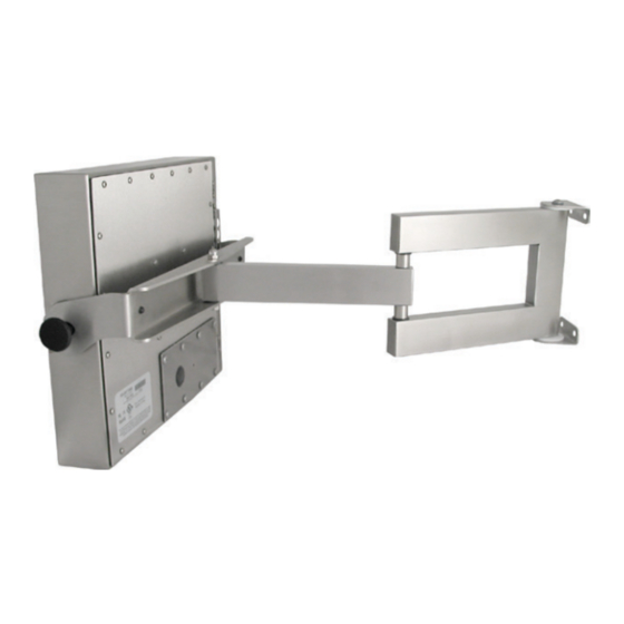
Installation Instructions Mount the Monitor Hope Industrial Systems offers a variety of mounting options for your Universal Mount Monitor. Individual installation instructions are shipped with the following products and may also be found on our website at the addresses listed below� Heavy Industrial Yoke Mounts The standard yoke may be used alone, with our benchtop mounting kit for through-surface cable routing, or with our Pedestal Mount for free-standing... - Page 13 Installation Instructions Heavy Industrial Arm Mounts Our wall arm mounting options range from solid wall yoke to fully articulating arms. Complete installation instructions are shipped with the following products and may also be found on our website at the following addresses: Wall Mount Arms (for YA _ _ -15 and YA _ _ -24 Series): https://www�HopeIndustrial�com/docs/99090 Wall Yoke (for YW _ _ -07 Series):...
- Page 14 Installation Instructions All Hope Industrial Universal Mount Monitors come standard with a 100 mm square VESA mounting pattern with M4 threads. Below is the VESA mounting diagram for Hope Industrial Universal Mount Monitors. Detailed installation instructions for specific VESA mounting options are shipped with the product and may also be found on our website at the following address: https://www�HopeIndustrial�com/docs/99034 IMPORTANT!
-
Page 15: Video Settings
Video Settings Video Settings Setting the Timing Mode Setting the timing mode of your computer graphics adapter (or other video source) is important for maximizing the quality of the screen image and for minimizing eye strain. The timing mode consists of the resolution (e.g. 1280 x 1024) and refresh rate (or vertical frequency; e.g. 60 Hz). After setting the timing mode, use the On-Screen Display (OSD) controls to adjust the screen image. -
Page 16: Control Panel Buttons
Video Settings Control Panel Buttons Use the control panel buttons located on the back of the monitor to display and adjust various settings on the On-Screen Display (OSD) menu. CONTROL PANEL BUTTONS 1� To display the Main Menu, press button [1]� NOTE: All OSD menus and adjustments screens disappear automatically after 15 seconds. -
Page 17: Osd And Power Lock Settings
Video Settings Button Control Functions Power • Turns the monitor on and off. • The Power Indicator light glows blue during normal operation and orange when the monitor is in Power Saving mode. Up / View Mode When the OSD menu IS NOT displayed: •... -
Page 18: On-Screen Display (Osd) Menus
Video Settings On-Screen Display (OSD) Menus To open the OSD menu, press button [1] once. The following screen will appear: Main Menu Description Auto Image Adjust Automatically sizes, centers, and fine tunes the video signal to eliminate waviness and distortion� Contrast / Brightness Includes the Contrast and Brightness functions. -
Page 19: Auto Image Adjust Menu
Video Settings Auto Image Adjust Menu The Auto Image Adjust menu automatically sizes, centers, and fine tunes the video signal to eliminate waviness and distortion� Press button [2] outside of the OSD menu to activate Auto Image Adjust. NOTE: Auto Image Adjust works with most common video cards. If this function does not work on your display, lower the video refresh rate to 60 Hz and set the resolution to its pre-set value�... -
Page 20: Color Adjust Menu
Video Settings Color Adjust Menu The Color Adjust menu provides several color adjustment modes, including preset color temperatures and a User Color mode which allows independent adjustment of red (R), green (G), and blue (B). The factory setting for this product is Native. Color Adjust Menu Description sRGB... -
Page 21: Information Menu
Video Settings Information Menu The Information menu displays the timing mode (video signal input) coming from the graphics card in the computer. See your graphics card's user guide for instructions on changing the resolution and refresh rate (vertical frequency)� NOTE: VESA 1280 x 1024 @ 60 Hz (recommended) means that the resolution is 1280 x 1024 and the refresh rate is 60 Hz�... -
Page 22: Setup Menu
Video Settings Manual Image Adjust Description ECO Mode Provides lower power consumption by reducing the brightness. • Standard is the default brightness setting. • Optimize reduces brightness by 25%. • Conserve reduces brightness by 50%. View Mode Allows the user to select from five image modes to find the optimal screen setting for different applications, as well as the default "Standard"... -
Page 23: Memory Recall Menu
Video Settings Setup Menu Description Language Select Allows the user to choose the language used in the menus and control screens� Resolution Notice Advises the optimal resolution to use� OSD Position Allows the user to move the OSD menus and control screens� OSD Time Out Sets the length of time the OSD screen is displayed. -
Page 24: Cleaning Instructions
Cleaning Instructions Cleaning Instructions CAUTION! DO NOT USE ABRASIVE MATERIALS, SUCH AS PAPER TOWELS OR DIRTY SHOP RAGS, ON THE DISPLAY AS IT WILL SCRATCH THE PROTECTIVE COATING. ALWAYS USE A SOFT CLOTH, PREFERABLY MADE OF COTTON. All displays may be cleaned using any standard glass cleaner as long as there is no abrasive or oily content. -
Page 25: Troubleshooting
Troubleshooting Troubleshooting Video Troubleshooting IMPORTANT! If using a KVM extender, first try to resolve any problems using the solutions listed below. If the problem still exists, try bypassing the KVM extender. If this fixes the problem and allows the monitor to work properly, then the KVM extender is the source of the problem�... - Page 26 Troubleshooting Symptom Causes Solutions "Out of The source signal exceeds Adjust the computer settings to the monitor's Range" the maximum resolution native resolution: message box and/or refresh rate that the 1280 x 1024 @ 60 Hz and no image monitor can handle on the screen ( >...
-
Page 27: Touch Screen Troubleshooting
Troubleshooting Touch Screen Troubleshooting Applies to touch screen monitors only� To be sure that you have the most current driver, please check the following Internet address: https://www�HopeIndustrial�com/support/drivers/ Symptom Causes Solutions No response Touch screen cable is not Make sure either the USB or Serial touch when touching plugged in correctly. -
Page 28: Specifications
Specifications Specifications Display Type Thin-film transistor (TFT) Active Matrix Liquid Crystal Size 19" diagonal Image Size (W x H) 374�8 mm x 299�8 mm (14�8" x 11�8") Native Resolution SXGA (1280 x 1024, 5:4 aspect ratio) Minimum Resolution VGA (640 x 480) Pixel Pitch 0�293 mm x 0�293 mm Number of Colors... -
Page 29: Video
Specifications Video Input Connectors • HD-15, DVI-D • Optional adapters are available for other connection types (contact Hope Industrial Systems for details) Input Signal Formats • RGB Analog video, 0.7/1.0 Vp-p, 75 Ohms Compatible sync modes: Separate H/V sync • NOTE: NTSC/PAL composite input available (call for details) Horizontal Scan 24 –... -
Page 30: Functional
Specifications Functional Control Panel Buttons Power, Up, Down, 2 (Enter), 1 (Menu) On-Screen Display (OSD) Auto Image Adjust, Contrast / Brightness, Input Select, Color Menus Adjust, Information, Manual Image Adjust, Setup, Memory Recall Touch Screen Option 5-wire single-touch resistive sensor; Serial (RS-232) and USB interface to host computer Compliances and Certifications Electrical... -
Page 31: Warranty Statement
Warranty Statement Warranty Statement Who is Covered? This warranty covers the purchaser of this product only and is not transferable without our written consent� What Does This Warranty Cover and What is the Period of Coverage? We warrant this product to be free from defects in material and workmanship, subject to the conditions set forth below. - Page 32 Hope Industrial Systems, Inc. US / International 1325 Northmeadow Parkway, Suite 100 Roswell, GA 30076 United States Toll Free: (877) 762-9790 | International: +1 (678) 762-9790 | Fax: +1 (678) 762-9789 Sales and Customer Service: sales@HopeIndustrial.com Support and Returns: support@HopeIndustrial.com Accounting Department: accounting@HopeIndustrial.com www.HopeIndustrial.com...
Need help?
Do you have a question about the HIS-UM19-H Series and is the answer not in the manual?
Questions and answers